Chapter 6O. Control of Traffic Through Traffic Incident Management Areas¶
§6O.01 General¶
Support
01. The National Incident Management System (NIMS) requires the use of the Incident Command System (ICS) at traffic incident management scenes.
02. A traffic incident is an emergency road user occurrence, a natural disaster, or other unplanned event that affects or impedes the normal flow of traffic.
03. A traffic incident management area is an area of a highway where temporary traffic controls are installed, as authorized by a public authority or the official having jurisdiction of the roadway, in response to a road user incident, natural disaster, hazardous material spill, or other unplanned incident. It is a type of TTC zone and extends from the first warning device (such as a sign, light, or cone) to the last TTC device or to a point where vehicles return to the original lane alignment and are clear of the incident.
04. Traffic incidents can be divided into three general classes of duration, each of which has unique traffic control characteristics and needs. These classes are:
- A. Major—expected duration of more than 2 hours,
- B. Intermediate—expected duration of 30 minutes to 2 hours, and
- C. Minor—expected duration under 30 minutes.
05. The primary functions of TTC at a traffic incident management area are to inform road users of the incident and to provide guidance information on the path to follow through the incident area. Alerting road users and establishing a well-defined path to guide road users through the incident area will serve to protect the incident responders and those involved in working at the incident scene and will aid in moving road users expeditiously past or around the traffic incident, will reduce the likelihood of secondary traffic crashes, and will preclude unnecessary use of the surrounding local road system. Examples include a stalled vehicle blocking a lane, a traffic crash blocking the traveled way, a hazardous material spill along a highway, and natural disasters such as floods and severe storm damage.
Guidance
06. In order to reduce response time for traffic incidents, highway agencies, appropriate public safety agencies (law enforcement, fire and rescue, emergency communications, emergency medical, and other emergency management), and private sector responders (towing and recovery and hazardous materials contractors) should mutually plan for occurrences of traffic incidents along the major and heavily traveled highway and street system.
07. On-scene responder organizations should train their personnel in TTC practices for accomplishing their tasks in and near traffic and in the requirements for traffic incident management contained in this Manual. On-scene responders should take measures to move the incident off the traveled roadway or to provide for appropriate warning. All on-scene responders and news media personnel should constantly be aware of their visibility to oncoming traffic and wear high-visibility apparel. Planning and training should include incorporation of estimated time durations to clear the event as part of their initial incident estimate. When events are deemed as probable Major Traffic Incidents that could generate prolonged lane or road closures, notification of all affected agencies should be initiated as part of the initial incident report that is provided to the emergency communications center who would then be responsible for making notifications to appropriate state, regional, and local agencies and resources for the purpose of ramping up and responding as quickly as possible thus facilitating a more rapid transition from emergency TTC to an MUTCD-compliant TTC zone when warranted.
08. Emergency vehicles arriving at an incident should be positioned in a manner that attempts to protect both the responders performing their duties and road users traveling through the incident scene, while minimizing, to the extent practical, disruption of the adjacent traffic flow. Emergency vehicle positions should optimize traffic flow through the incident scene. All emergency vehicles that subsequently arrive should be positioned in a manner that does not interfere with the established temporary traffic flow.
09. Responders arriving at a traffic incident should estimate the magnitude of the traffic incident, the expected time duration of the traffic incident, and the expected vehicle queue length, and then should set up the appropriate temporary traffic controls for these estimates.
Option
10. Warning and guide signs used for TTC traffic incident management situations may have a black legend and border on a fluorescent pink background (see Figure 6O-1).
Support
11. While some traffic incidents might be anticipated and planned for, emergencies and disasters might pose more severe and unpredictable problems. The ability to quickly install proper temporary traffic controls might greatly reduce the effects of an incident, such as secondary crashes or excessive traffic delays. An essential part of fire, rescue, spill clean-up, highway agency, and enforcement activities is the proper control of road users through the
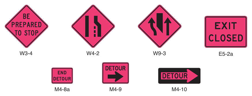
traffic incident management area in order to protect responders, victims, and other personnel at the site. These operations might need corroborating legislative authority for the implementation and enforcement of appropriate road user regulations, parking controls, and speed zoning. It is desirable for these statutes to provide sufficient flexibility in the authority for, and implementation of, TTC to respond to the needs of changing conditions found in traffic incident management areas.
Option
12. For traffic incidents, particularly those of an emergency nature, TTC devices on hand may be used for the initial response as long as they do not themselves create unnecessary additional hazards.
Support
13. The establishment, maintenance, and prompt removal of lane diversions can be effectively managed by interagency planning that includes representatives of highway and public safety agencies.
Guidance
14. All traffic control devices needed to set up the TTC at a traffic incident should be available so that they can be readily deployed for all major and intermediate traffic incidents. The TTC should include the proper traffic diversions, tapered lane closures, and upstream warning devices to alert traffic approaching the queue and to encourage early diversion to an appropriate alternative route.
15. Attention should be paid to the upstream end of the traffic queue such that warning is given to road users approaching the back of the queue.
16. If manual traffic control is needed, it should be provided by qualified flaggers or uniformed law enforcement officers.
Option
17. If flaggers are used to provide traffic control for an incident management situation, the flaggers may use appropriate traffic control devices that are readily available or that can be brought to the traffic incident scene on short notice.
Guidance
18. When light sticks or flares are used to establish the initial traffic control at incident scenes, channelizing devices (see Section 6K.01) should be installed as soon thereafter as practical.
Option
19. The light sticks or flares may remain in place if they are being used to supplement the channelizing devices.
Guidance
20. The light sticks, flares, and channelizing devices should be removed after the incident is terminated.
§6O.02 Major Traffic Incidents¶
Ohio-modified
Ohio amends this section per the Ohio Supplement to the MUTCD, 11th Edition (effective January 16, 2026). The National MUTCD text is shown above; below is Ohio's amended text, as published in the supplement (deletions removed, additions kept).
Supplement directives: - The Ohio Supplement replaces Section 6O.02 of the National MUTCD in its entirety; the amended text is shown below. - The Ohio Supplement also replaces Table 6P-1 (see the supplement PDF for the revised artwork). - The Ohio Supplement also replaces Figure 6P-15 (see the supplement PDF for the revised artwork). - The Ohio Supplement also replaces Figure 6P-24 (see the supplement PDF for the revised artwork). - The Ohio Supplement also replaces Figure 6P-25 (see the supplement PDF for the revised artwork). - The Ohio Supplement also replaces Figure 6P-26 (see the supplement PDF for the revised artwork). - The Ohio Supplement also replaces Figure 6P-31 (see the supplement PDF for the revised artwork). - The Ohio Supplement also replaces Figure 6P-32 (see the supplement PDF for the revised artwork). - The Ohio Supplement also replaces Figure 6P-36 (see the supplement PDF for the revised artwork). - The Ohio Supplement also replaces Figure 6P-38 (see the supplement PDF for the revised artwork). - The Ohio Supplement also replaces Figure 6P-39 (see the supplement PDF for the revised artwork). - The Ohio Supplement also replaces Figure 6P-41 (see the supplement PDF for the revised artwork). - The Ohio Supplement also replaces Figure 6P-45 (see the supplement PDF for the revised artwork). - The Ohio Supplement also replaces Figure 7B-1 (see the supplement PDF for the revised artwork).
Support: 01. Major traffic incidents are typically traffic incidents involving hazardous materials, fatal traffic crashes involving numerous vehicles, and other natural or man-made disasters. These traffic incidents typically involve closing all or part of a roadway facility for a period exceeding 2 hours.
Guidance: 02. If the traffic incident is anticipated to last more than 24 hours, applicable procedures and devices set forth in other Chapters of Part 6 should be used. 1 _ 02a For guidance on the use of regulatory signs due to high water, see Section 6G.04 and Section 2B.63.
Support: 03. A road closure can be caused by a traffic incident such as a road user crash that blocks the traveled way. Road users are usually diverted through lane shifts or detoured around the traffic incident and back to the original roadway. A combination of traffic engineering and enforcement preparations is needed to determine the detour route, and to install, maintain, or operate, and then to remove the necessary traffic control devices when the detour is terminated. Large trucks are a significant concern in such a detour, especially when detouring them from a controlled-access roadway onto local or arterial streets.
04. During traffic incidents, large trucks might need to follow a route separate from that of automobiles because of bridge, weight, clearance, or geometric restrictions. Also, vehicles carrying hazardous material might need to follow a different route from other vehicles.
05. Some traffic incidents such as hazardous material spills might require closure of an entire highway. Through road users must have adequate guidance around the traffic incident. Maintaining good public relations is desirable. The cooperation of the news media in publicizing the existence of, and reasons for, traffic incident management areas and their TTC can be of great assistance in keeping road users and the general public well informed. Page OH Part 6-18 Chapter 6P – Typical Applications 1. Regulatory traffic control devices should be modified as needed for the duration of the detour. 1a. If the road is opened for some distance beyond the intersection and/or there are significant origin/destination points beyond the intersection, the ROAD CLOSED and DETOUR signs on Type 3 Barricades should be located at the edge of the traveled way. 2. If the road is opened for some distance beyond the intersection and/or there are significant origin/destination points beyond the intersection, the ROAD CLOSED and DETOUR signs on Type 3 Barricades may be located at the edge of the traveled way. 2a. If the road is closed a short distance beyond the intersection and there are few origin/destination points beyond (for example, a few residences), the Type 3 Barricades shown in the typical application may be moved to the center of the traveled lanes. 2b. If the barricades are located as in Note 2a above, the ROAD CLOSED and DETOUR signs shall be placed only on the barricade centered in the lane of travel of traffic approaching the closure. The barricade centered in the lane of travel of departing traffic shall not be signed. The barricades in adjacent lanes shall be offset longitudinally from each other an adequate distance in order to permit traffic to travel around the barricades (the barricade in the road user’s lane located in advance of the barricade located left of the center line). 3. A Route Sign Directional assembly may be placed on the far left corner of the intersection to augment or replace the one shown on the near right corner. 4. Flashing warning lights and/or flags may be used to call attention to the advance warning signs. 5. Cardinal direction plaques may be used with route signs. Page OH Part 6-21 Figure 6P-8 - Roads Closed with an Off-Site Detour r ROAD l R11-2 ~ 500 ft l .&, rioAD CLOSED lxx II MILES AHEAD R11-3a lL!-OCAL TRArFIC ONLY ' DETOUR F •·10L .&. M4·8 1,000 fl M1-5 Nate: See Table 6P-2 for the meanill s of the symbols used in this figu~e. ' t Typical Application a W20·2 Page OH Part 6-22 Notes for Figure 6P-15 – Typical Application 15 Work in the Center of a Road with Low Traffic Volumes 1. The lanes on either side of the center work space should have a minimum width of 10 feet as measured from the near edge of the channelizing devices to the edge of the pavement or the outside edge of the paved shoulder. 1a. Except as provided in Note 1b, the shifting taper should have a length of approximately L (see Tables 6B-3 and 6B-4). 1b. Where speeds are less than 50 mph, the shifting taper may have a length of approximately ½ L (see Tables 6B-3 and 6B-4). 2. Positive protection devices may be used per Section 6M.02. 3. Flashing warning lights and/or flags may be used to call attention to the advance warning signs. 4. If the closure continues overnight, warning lights may be used on the channelizing devices. 5. A lane width of 9 feet may be used for short-term stationary work on low-volume, low-speed roadways when motor vehicle traffic does not include longer and wider heavy commercial vehicles. 6. A work vehicle displaying high-intensity rotating, flashing, oscillating, or strobe lights may be used instead of the channelizing devices forming the tapers or the high-level warning devices. 7. Vehicle hazard warning signals may be used to supplement high-intensity rotating, flashing, oscillating, or strobe lights. 8. Vehicle hazard warning signals shall not be used instead of the vehicle’s high-intensity rotating, flashing, oscillating, or strobe lights. Page OH Part 6-23 1. If the work space extends across a crosswalk, the crosswalk should be closed using the information and devices shown in Figure 6P-29. 2. When turn prohibitions are implemented, two turn prohibition signs should be used, one on the near side and, space permitting, one on the far side of the intersection. I -2a. E_xcept as pr_ovided in No te 2b, the shifting taper should have a length of approximately L (see Tables 6B-3 and 6B-4). 2b. Where speeds are less than 50 mph, the shifting taper may have a length of approximately ½ L (see Tables 6B-3 and 6B-4). 3. Positive protection devices may be used per Section 6M.02. 4. A buffer space may be used between opposing directions of vehicular traffic as shown in this application. 5. When the normal procedure of closing on the near side of the intersection any lane that is not carried through the intersection results in the closure of a right-hand lane having significant right- turn movements, then the right-hand lane may be restricted to right turns only, requiring through traffic to use the left lane. 6. Where the turning radius is large, a right-turn island using channelizing devices or pavement markings may be used. 7. If there is insufficient space to place the back-to-back Keep Right sign and No Left Turn symbol signs at the end of the row of channelizing devices separating opposing vehicular traffic flows, the No Left Turn symbol sign may be placed on the right and the Keep Right sign may be omitted. 8. For intersection approaches reduced to a single lane, left-turn movements may be prohibited to maintain capacity for through vehicular traffic. 9. Flashing warning lights and/or flags may be used to call attention to advance warning signs. 10. Temporary pavement markings may be used to delineate the travel path through the intersection. 11. If dimension “A” is not available to create a temporary right-turn lane, continuous channelizers may be installed from the end of the taper to the intersection and, as a result, the RIGHT LANE MUST TURN RIGHT signs would not be installed. Page OH Part 6-25 1. If the work space extends across a crosswalk, the crosswalk should be closed using the information and devices shown in Figure 6P-29. 1a. Except as provided in Note 1b, the shifting taper should have a length of approximately L (see Tables 6B-3 and 6B-4). 1b. Where speeds are less than 50 mph, the shifting taper may have a length of approximately ½ L (see Tables 6B-3 and 6B-4). 2. The normal procedure is to close on the near side of the intersection any lane that is not carried through the intersection, as shown. 3. Positive protection devices may be used per Section 6M.02. 4. If the left-turn movement that normally uses the closed turn bay is small and/or the gaps in opposing vehicular traffic are frequent, left turns may be permitted on that approach. 5. Flashing warning lights and/or flags may be used to call attention to the advance warning signs. Page OH Part 6-27 1. All lanes should be a minimum of 10 feet in width as measured to the near face of the channelizing devices. 1a. Except as provided in Note 1b, the shifting taper should have a length of approximately L (see Tables 6B-3 and 6B-4). I -1b. W_here spee_ds are less th an 50 mph, the shifting taper may have a length of approximately ½ L (see Tables 6B-3 and 6B-4). 2. A high-level warning device may be placed in the work space, if there is sufficient room. 3. For short-term use on low-volume, low-speed roadways with vehicular traffic that does not include longer and wider heavy commercial vehicles, a minimum lane width of 9 feet may be used. 4. Flashing warning lights and/or flags may be used to call attention to advance warning signs. 5. Left turns may be prohibited as required by geometric conditions, such as where the streets are so narrow that it might be physically impossible to turn left, especially for large vehicles. 6. For short-duration work operations, the channelizing devices may be eliminated if a vehicle displaying high-intensity rotating, flashing, oscillating, or strobe lights is positioned in the work space. 7. Vehicle hazard warning signals may be used to supplement high-intensity rotating, flashing, oscillating, or strobe lights. 8. Vehicle hazard warning signals shall not be used instead of the vehicle’s high-intensity rotating, flashing, oscillating, or strobe lights. Page OH Part 6-29
Standard: 0. Taper W20-1 '• ~! G20-2 ♦1 ~ -----A--- 10ft (o.pt.io.n al) -I .. ~--·H••-- ... MIN. t 10 ft MIN. + ..... ..... l ---+1--+-\ .7~:1n, (optional) Taper HD& OVON (optional) (optional) Note: See Table 6P-2 forthe meanings of the symbols us!ld in this figurn. t See Table 6B-1 for the meanings ot the lener code.s us.e<f ,In tlhlcS "9 u e. W20·1 See Table 68-4 for formulas for calculia.ting taper length (L). Typical Application .26 Page OH Part 6-30 Notes for Figure 6P-31 – Typical Applications 31 Lane Closure on a Street with Uneven Directional Volumes 1. The illustrated information shall be used only when the vehicular traffic volume indicates that two lanes of vehicular traffic shall be maintained in the direction of travel for which one lane is closed. 2. The procedure may be used during a peak period of vehicular traffic and then changed to provide two lanes in the other direction for the other peak. 3. For high speeds, a LEFT LANE CLOSED XX FT sign should be added for vehicular traffic approaching the lane closure, as shown in Figure 6P-32. 3a. Except as provided in Note 3b, the shifting taper should have a length of approximately L (see Tables 6B-3 and 6B-4). 3b. Where speeds are less than 50 mph, the shifting taper may have a length of approximately ½ L (see Tables 6B-3 and 6B-4). 4. Conflicting pavement markings should be removed for long-term projects. For short-term and intermediate-term projects where this is impracticable, the channelizing devices in the area where the pavement markings conflict should be placed at a maximum spacing of ½ S feet where S is the speed in mph. Temporary markings should be installed where needed. 5. If the lane shift has curves with recommended speeds of 30 mph or less, Reverse Turn signs should be used. 6. Where the shifted section is long, a Reverse Curve sign should be used to show the initial shift and a second sign should be used to show the return to the normal alignment. 7. If the tangent distance along the temporary diversion is less than 600 feet, the Double Reverse Curve sign should be used at the location of the first Two Lane Reverse Curve sign. The second Two Lane Reverse Curve sign should be omitted. 8. Except as provided in Note 11 below, the number of lanes illustrated on the Reverse Curve or Double Reverse Curve signs shall be the same as the number of through lanes available to road users, and the direction of the reverse curves shall be appropriately illustrated. 9. Positive protection devices may be used per Section 6M.02. 10. A longitudinal buffer space may be used in the activity area to separate opposing vehicular traffic. 11. Where two or more lanes are being shifted, a Reverse Curve (or Reverse Turn) sign with an ALL LANES plaque (see Figure 6H-1) may be used instead of a sign that illustrates the number of lanes. 12. Where more than three lanes are being shifted, the Reverse Curve (or Turn) sign may be rectangular. 13. A work vehicle or a shadow vehicle may be equipped with a truck-mounted attenuator. Page OH Part 6-31
Option: 1. t lemporary solid --IE---- -.:i A white lane ine l Wl-4bFI • s = ~peed in mph W1-4bL 4S ft' Noles:See Table 6P•2 tot lhe_meanin[JS or lhe SI/ bols used in 1h1s t19ure. See 'l"a'ble 6&-1 ror 1ne mean,ngs or lh.e lelter codes used in !his ligme. W:Z0-1 See Table 68-4 for formulas far calcul'atlng tap r lcng1h tL). Typical Application 31 *"' See Nol:€s 3a and 3b. Page OH Part 6-32 Notes for Figure 6P-32 – Typical Application 32 Half Road Closure on a Multi-Lane, High-Speed Highway 1. Pavement markings no longer applicable shall be removed or obliterated as soon as practical. Except for intermediate-term and short-term situations, temporary markings shall be provided to clearly delineate the temporary travel path. For short-term and intermediate-term situations where it is not feasible to remove and restore pavement markings, channelization shall be made dominant by using a very close device spacing. 1a. Except as provided in Note 1b, the shifting taper should have a length of approximately L (see Tables 6B-3 and 6B-4). 1b. Where speeds are less than 50 mph, the shifting taper may have a length of approximately ½ L (see Tables 6B-3 and 6B-4). 2. When paved shoulders having a width of 8 feet or more are closed, channelizing devices should be used to close the shoulder in advance of the merging taper to direct vehicular traffic to remain within the traveled way. 3. Where channelizing devices are used instead of pavement markings, the maximum spacing should be ½ S feet where S is the speed in mph. 4. If the tangent distance along the temporary diversion is less than 600 feet, a Double Reverse Curve sign should be used instead of the first Reverse Curve sign, and the second Reverse Curve sign should be omitted. 5. Positive protection devices may be used per Section 6M.02. 6. Warning lights may be used to supplement channelizing devices at night. 7. A truck-mounted attenuator may be used on the work vehicle and/or the shadow vehicle. Page OH Part 6-33 1. The lane shift should be used when the work space extends into either the right-hand or left-hand lane of a divided highway and it is impracticable, for capacity reasons, to reduce the number of available lanes. 1a. Except as provided in Note 1b, the shifting taper should have a length of approximately L (see Tables 6B-3 and 6B-4). 1b. Where speeds are less than 50 mph, the shifting taper may have a length of approximately ½ L (see Tables 6B-3 and 6B-4). 2. When a lane shift is accomplished by using (1) geometry that meets the design speed at which the permanent highway was designed, (2) full normal cross-section (full lane width and full shoulders), and (3) complete pavement markings, then only the initial general work-zone warning sign is required. 3. When the conditions in Note 2 above are not met, the information shown in the typical application should be employed and the provisions in Notes 4 through 17 below are applicable. 4. Temporary traffic barriers, if used, shall comply with the provisions of Section 6M.02. 5. The barrier shall not be placed along the shifting taper. The lane shall first be shifted using channelizing devices and pavement markings. 6. A warning sign should be used to show the changed alignment. 7. Except as provided in Note 8 below, the number of lanes illustrated on the Reverse Curve signs shall be the same as the number of through lanes available to road users, and the direction of the reverse curves shall be appropriately illustrated. 8. Where two or more lanes are being shifted, a W1-4 (or W1-3) sign with an ALL LANES (W24- 1cP) plaque (see Figure 6H-1) may be used instead of a sign that illustrates the number of lanes. 9. Where more than three lanes are being shifted, the Reverse Curve (or Turn) sign may be rectangular. 10. Where the shifted section is longer than 600 feet, one set of Reverse Curve signs should be used to show the initial shift and a second set should be used to show the return to the normal alignment. If the tangent distance along the temporary diversion is less than 600 feet, a Double Reverse Curve sign should be used instead of the first Reverse Curve sign, and the second Reverse Curve sign should be omitted. 11. If a STAY IN LANE sign is used, then solid white lane lines should be used. 12. The minimum width of the shoulder lane shall be 10 feet. 13. For long-term stationary work, existing conflicting pavement markings shall be removed and temporary markings shall be installed before traffic patterns are changed. 14. For short-term stationary work, lanes may be delineated by channelizing devices or removable pavement markings instead of temporary markings. Page OH Part 6-35 15. If the shoulder cannot adequately accommodate trucks, trucks should be directed to use the travel lanes. 16. The use of a barrier should be based on engineering judgment. 17. Type C Steady-Burn warning lights may be placed on channelizing devices and the barrier parallel to the edge of the pavement for nighttime lane closures. Page OH Part 6-36 .. SbifliogJ:a n,eI (optional) (o L p ig ti h o ti n n a g l) ~ - -+-- - -1------- Tem e p d o g r e a r l y in w e hite Lighting I (optional) 1/3 L t t t e Notes 7 and 8) A I ~ W1-4cR (optional) Notes: Soo Table 6P-2 for the meanings of the symbols used in this figure. Soo Tab-le 68-1 for the meanings of the letter codes used in this figure. See TatJ.l1:1 68•4 for formulas for calculating taper length tL). ¼ See Notes 1a and 1b. W20-1 Typical Appllcatlon 36 Page OH Part 6-37 Notes for Figure 6P-38 - Typical Application 38 Interior Lane Closure on a Freeway 1. An arrow board shall be used when a freeway lane is closed. When more than one freeway lane is closed, a separate arrow board shall be used for each closed lane. 2. If temporary traffic barriers are installed, they shall comply with the provisions and requirements in Section 6M.02. 3. The barrier shall not be placed along the shifting taper. The lane shall first be shifted using channelizing devices and pavement markings. 4. For long-term stationary work, existing conflicting pavement markings shall be removed and temporary markings shall be installed before traffic patterns are changed. 5. For a long-term closure, a barrier should be used to provide additional safety to the operation in the closed interior lane. A buffer space should be used at the upstream end of the closed interior lane. 6. An arrow board displaying an arrow pointing to the right should be placed on the left-hand shoulder at the beginning of the taper. 7. For long-term use, the broken lane lines should be made solid white in the two-lane section. I -7a. E_xcept as pr_ovided in No te 7b, the shifting taper should have a length of approximately L (see Tables 6B-3 and 6B-4). I -7b. W_here spee_ds are less th an 50 mph, the shifting taper may have a length of approximately ½ L (see Tables 6B-3 and 6B-4). 8. As an alternative to initially closing the left-hand lane, as shown in the typical application, the right-hand lane may be closed in advance of the interior lane closure with appropriate channelization and signs. The Interior Lane Shift Ahead symbol sign may be mirrored to indicate a right lane shift. 9. A short, single row of channelizing devices in advance of the vehicular traffic split to restrict vehicular traffic to their respective lanes may be added. 10. DO NOT PASS signs may be used. 11. If a paved shoulder having a minimum width of 10 feet and sufficient strength is available, the left-hand and center lanes may be closed and motor vehicle traffic carried around the work space on the right-hand lane and a right-hand shoulder. 12. A work vehicle with a truck-mounted attenuator may be used within the closed interior lane between the buffer space and the work area. 13. Positive protection devices may be used per Section 6M.02. 14. When a shoulder lane is used that cannot adequately accommodate trucks, trucks should be directed to use the normal travel lanes. Page OH Part 6-38 Tempora,y solid double "'Shifting Taper ~ while lane line I STAY IN LANE
Guidance: 2L. R4-9 Temporary--....,--- yellow edge line Noles:See Table 6P-2 or the meanings of the symbols use<l in this figure. See lab!e ,sB-1 lor the meanings of t t t the letter codes used in this figure. See Table f'lB-4 lor formulas for caloule.ting tE1per fength (L) . .. See Notes 7a and 7b. Typical Applllcation 38 Page OH Part 6-39 Notes for Figure 6P-39 – Typical Application 39 Median Crossover on a Freeway 1. Channelizing devices or temporary traffic barriers shall be used to separate opposing vehicular traffic. 2. An arrow board shall be used when a freeway lane is closed. When more than one freeway lane is closed, a separate arrow board shall be used for each closed lane. 3. For long-term work on high-speed, high-volume highways, consideration should be given to using a temporary traffic barrier to separate opposing vehicular traffic. I -3a. E_xcept as pr_ovided in No te 3b, the shifting taper should have a length of approximately L (see Tables 6B-3 and 6B-4). I -3b. W_here spee_ds are less_ th an 50 mph, the shifting taper may have a length of approximately ½ L (see Tables 6B-3 and 6B-4). 4. When a temporary traffic barrier is used to separate opposing vehicular traffic, the Two-Way Traffic, DO NOT PASS, KEEP RIGHT, and DO NOT ENTER signs may be eliminated. 5. The alignment of the crossover may be designed as a reverse curve. 6. When the crossover follows a curved alignment, the design criteria contained in the “AASHTO Green Book – A Policy On Geometric Design of Highways and Streets,” 7th Edition, 2018 AASHTO should be used. 7. When channelizing devices have the potential of leading vehicular traffic out of the intended traffic space, the channelizing devices should be extended a distance in feet of 2 times the speed limit in mph beyond the downstream end of the transition area as depicted. 8. Where channelizing devices are used, the Two-Way Traffic signs should be repeated every 1 mile. 9. NEXT XX MILES Supplemental Distance plaques may be used with the Two-Way Traffic signs, where XX is the distance to the downstream end of the two-way section. 10. When the distance is sufficiently short that road users entering the section can see the downstream end of the section, they are less likely to forget that there is opposing vehicular traffic. 11. The sign legends for the four pairs of signs approaching the lane closure for the non-crossover direction of travel are not shown. They are similar to the series shown for the crossover direction, except that the left-hand lane is closed. 12. Positive protection devices may be used per Section 6M.02. Page OH Part 6-40 1. This typical application should be used for carrying an exit ramp across a closed directional roadway of a divided highway. The design criteria contained in the “AASHTO Green Book – A Policy On Geometric Design of Highways and Streets,” 7th Edition, 2018, AASHTO should be used for determining the curved alignment. 2. The guide signs should indicate that the ramp is open, and where the temporary ramp is located. Conversely, if the ramp is closed, guide signs should indicate that the ramp is closed. 3. When the exit is closed, a black-on-orange EXIT CLOSED sign panel should be placed diagonally across the interchange/intersection guide signs and channelizing devices should be placed to physically close the ramp. 4. In the situation (not shown) where channelizing devices are placed along the mainline roadway, the devices’ spacing should be reduced in the vicinity of the off ramp to emphasize the opening at the ramp itself. Channelizing devices and/or temporary pavement markings should be placed on both sides of the temporary ramp where it crosses the median and the closed roadway. 5. Advance guide signs providing information related to the temporary exit should be relocated or duplicated adjacent to the temporary roadway. 6. A temporary EXIT sign shall be located in the temporary gore. For better visibility, it shall be mounted a minimum of 7 feet from the pavement surface to the bottom of the sign. 7. Positive protection devices may be used per Section 6M.02. 8. Guide signs referring to the exit may need to be relocated to the median. 9. The temporary EXIT sign placed in the temporary gore may be either black on orange or white on green. 10. In some instances, a temporary deceleration lane may be useful in facilitating the exiting maneuver. 11. When a temporary traffic barrier is used to separate opposing vehicular traffic, the Two-Way Traffic signs may be omitted. Page OH Part 6-42 1. This application addresses one of several uses for movable barriers (see Section 6M.02) in highway TTC zones. In this example, one side of a 6-lane divided highway is closed to perform the work operation, and vehicular traffic is carried in both directions on the remaining 3-lane roadway by means of a median crossover. To accommodate unbalanced peak-period vehicular traffic volumes, the direction of travel in the center lane is switched to the direction having the greater volume, with the transfer typically being made twice daily. Thus, there are four vehicular traffic phases described as follows: a. Phase A—two travel lanes northbound and one lane southbound; b. Transition A to B—one travel lane in each direction; c. Phase B—one travel lane northbound and two lanes southbound; and d. Transition B to A—one travel lane in each direction. The typical application on the left illustrates the placement of devices during Phase A. The typical application on the right shows conditions during the transition (Transition A to B) from Phase A to Phase B. 2. For the reversible lane situation depicted, the ends of the movable barrier should terminate in a protected area or a crash cushion should be provided. During Phase A, the transfer vehicle should be parked behind the downstream end of the movable barrier for southbound traffic as shown in the typical application on the left. During Phase B, the transfer vehicle should be parked between the downstream ends of the movable barriers at the north end of the TTC zone as shown in the typical application on the right. The transition shift from Phase A to B should be as follows: a. Change the signs in the northbound advance warning area and transition area from a LEFT LANE CLOSED AHEAD to a 2 LEFT LANES CLOSED AHEAD. Change the mode of the second northbound arrow board from Caution to Right Arrow. b. Place channelizing devices to close the northbound center lane. c. Move the transfer vehicle from south to north to shift the movable barrier from the west side to the east side of the reversible lane. d. Remove the channelizing devices closing the southbound center lane. e. Change the signs in the southbound transition area and advance warning area from a 2 LEFT LANES CLOSED AHEAD to a LEFT LANE CLOSED AHEAD. Change the mode of the second southbound arrow board from Right Arrow to Caution. 3. Where the lane to be opened and closed is an exterior lane (adjacent to the edge of the traveled way or the work space), the lane closure should begin by closing the lane with channelizing devices placed along a merging taper using the same information employed for a stationary lane closure. The lane closure should then be extended with the movable-barrier transfer vehicle moving with vehicular traffic. When opening the lane, the transfer vehicle should travel against vehicular traffic. The merging taper should be removed in a method similar to a stationary lane closure. 3a. Except as provided in Note 3b, the shifting taper should have a length of approximately L (see Tables 6B-3 and 6B-4). Page OH Part 6-44 I -3b. W_here spee_ds are less_ th an 50 mph, the shifting taper may have a length of approximately ½ L (see Tables 6B-3 and 6B-4). 4. The procedure may be used during a peak period of vehicular traffic and then changed to provide two lanes in the other direction for the other peak. 5. A longitudinal buffer space may be used in the activity area to separate opposing vehicular traffic. 6. A work vehicle or a shadow vehicle may be equipped with a truck-mounted attenuator. 7. An arrow board shall be used when a freeway lane is closed. When more than one freeway lane is closed, a separate arrow board shall be used for each closed lane. Page OH Part 6-45
Standard: 20. S5-1 AHEAD $4-7P WHEN W16-9P "' W16-7P ALL YEAR (optional) 7:30•8:30 AM S4-1P FLASHING S4-3P 2:3(>-3°30 PM OR SCHOOL (optional) OR FINES R2-6P II 200 FT II W 16-2aP .O,R Ct- M llL < O E R N E N S4-2P HIGHER (optional) OR 1rzlw16-5P AA[ PRESENT OR lt.=J (optional) f2oo1 OR FINES R2-6aP lliWW16-2P OR WHEN * DOUBLE (optional) rLASHING S4-4P .O,R (optional) OR OR l ~ t.=J I ( W op 1 t 6 io -5 n P a l) 7 2 ' : 3 3 0 0 • 0 8 : : J 3 O 0 A PM M S4-1 p ~ IR2-6bP ~(optional) W16-6P * (optional) If used, the assembly or sign wilh WHEN FLASHING legend shall be accompanied by a flashing yellow Speed Limtt Sign Beacon (see Section 4S.04). S3·1 S3-2 S4-5 S4-5a END ZONE $5-2 $5-3 R2-10 R2-11 Page OH Part 7-2
Support
01. Major traffic incidents are typically traffic incidents involving hazardous materials, fatal traffic crashes involving numerous vehicles, and other natural or man-made disasters. These traffic incidents typically involve closing all or part of a roadway facility for a period exceeding 2 hours.
Guidance
02. If the traffic incident is anticipated to last more than 24 hours, applicable procedures and devices set forth in other Chapters of Part 6 should be used.
Support
03. A road closure can be caused by a traffic incident such as a road user crash that blocks the traveled way. Road users are usually diverted through lane shifts or detoured around the traffic incident and back to the original roadway. A combination of traffic engineering and enforcement preparations is needed to determine the detour route, and to install, maintain, or operate, and then to remove the necessary traffic control devices when the detour is terminated. Large trucks are a significant concern in such a detour, especially when detouring them from a controlled-access roadway onto local or arterial streets.
04. During traffic incidents, large trucks might need to follow a route separate from that of automobiles because of bridge, weight, clearance, or geometric restrictions. Also, vehicles carrying hazardous material might need to follow a different route from other vehicles.
05. Some traffic incidents such as hazardous material spills might require closure of an entire highway. Through road users must have adequate guidance around the traffic incident. Maintaining good public relations is desirable. The cooperation of the news media in publicizing the existence of, and reasons for, traffic incident management areas and their TTC can be of great assistance in keeping road users and the general public well informed.
§6O.03 Intermediate Traffic Incidents¶
Support
Intermediate traffic incidents typically affect travel lanes for a time period of 30 minutes to 2 hours, and usually require traffic control on the scene to divert road users past the blockage. Full roadway closures might be needed for short periods during traffic incident clearance to allow traffic incident responders to accomplish their tasks.
§6O.04 Minor Traffic Incidents¶
Support
01. Minor traffic incidents are typically disabled vehicles and minor crashes that result in lane closures of less than 30 minutes. On-scene responders are typically law enforcement and towing companies, and occasionally highway agency service patrol vehicles.
02. Diversion of traffic into other lanes is often not needed or is needed only briefly. It is not generally possible or practical to set up a lane closure with traffic control devices for a minor traffic incident. Traffic control is the responsibility of on-scene responders.
Guidance
03. When a minor traffic incident blocks a travel lane, the vehicles involved in the incident should be moved from the blocked lane to the shoulder as quickly as possible.
§6O.05 Use of Emergency-Vehicle Lighting¶
Support
01. The use of emergency-vehicle lighting (such as high-intensity rotating, flashing, oscillating, or strobe lights) is essential, especially in the initial stages of a traffic incident, for the safety of emergency responders and persons involved in the traffic incident, as well as road users approaching the traffic incident. Emergency-vehicle lighting, however, provides warning only and provides no effective traffic control. The use of too many lights at an incident scene can be distracting and can create confusion for approaching road users, especially at night. Road users approaching the traffic incident from the opposite direction on a divided facility are often distracted by emergency vehicle lighting and slow their vehicles to look at the traffic incident posing a hazard to themselves and others traveling in their direction.
02. The use of emergency-vehicle lighting can be reduced if good traffic control has been established at a traffic incident scene. This is especially true for major traffic incidents that might involve a number of emergency vehicles. If good traffic control is established through placement of advance warning signs and traffic control devices to divert or detour traffic, then public safety agencies can perform their tasks on scene with minimal emergency-vehicle lighting.
Guidance
03. Public safety agencies should examine their policies on the use of emergency-vehicle lighting, especially after a traffic incident scene is secured, with the intent of reducing the use of this lighting as much as possible while not endangering those at the scene. Special consideration should be given to reducing or extinguishing forward facing emergency-vehicle lighting, especially on divided roadways, to reduce distractions to oncoming road users.
04. Because the glare from floodlights or vehicle headlights can impair the nighttime vision of approaching road users, any floodlights or vehicle headlights that are not needed for illumination, or to provide notice to other road users of an incident response vehicle being in an unexpected location, should be turned off at night.