Chapter 6P. Typical Applications¶
§6P.01 Typical Applications¶
Support
01. Chapter 6N contains discussions of typical TTC activities. Section 6A.02 contains discussions on development of TTC plans for the various activities. This Chapter presents typical applications for a variety of situations commonly encountered. While not every situation is addressed, the information illustrated can generally be adapted to a broad range of conditions. In many instances, an appropriate TTC plan is achieved by combining features from various typical applications. For example, work at an intersection might present a near-side TTC zone for one street and a far-side TTC zone for the other street. These treatments are found in two different typical applications, while a third typical application shows how to handle pedestrian crosswalk closures.
02. In general, the procedures illustrated represent minimum solutions for the situations depicted. Except for the notes (which are clearly classified using headings as being Standard, Guidance, Option, or Support), the information presented in the typical applications can generally be regarded as Guidance.
Option
03. TTC plans may deviate from the typical applications described in this Chapter to allow for conditions and requirements of a particular site or jurisdiction.
04. Other devices may be added to supplement the devices and device spacing may be adjusted to provide additional reaction time or delineation. Fewer devices may be used based on field conditions.
Support
05. Figures and tables found throughout Part 6 provide information for the development of TTC plans.
06. (DE Revision) Table 6P-1 is an index of the typical applications. In the printed version, the typical applications are shown on the right-hand page with notes on the facing page to the left. In the electronic version, the notes are shown on the page preceding the figure. The legend for the symbols used in the typical applications is provided in Table 6P-2. In many of the typical applications, sign spacings and other dimensions are indicated by letters using the criteria provided in Table 6B-1. The formulas for determining taper lengths are provided in Table 6B-4.
07. Most of the typical applications show TTC devices for only one direction.
§6P.01A Truck-Mounted Attenuator (TMA) Guidelines for Planned Work Activities¶
Support
01. (DE Revision) Shadow vehicles are used to warn motor vehicle traffic of the operation ahead. References to truck-mounted attenuators are also applicable to tow-behind or trailer attenuators. Work zones that exceed intermediate-term stationary durations on state-maintained roadways with high anticipated operating speeds that provide workers no means of escape from motorized traffic intruding into the workspace are to reference the “Work Zone Safety & Mobility - Procedures and Guidelines” for additional considerations.
Standard
02. (DE Revision) Required truck-mounted attenuators shall be provided as described within the typical applications and Table 6P-3 shall be followed when the truck-mounted attenuator is shown as optional within the typical applications.
Option
03. (DE Revision) Optional truck-mounted attenuators, as described within the typical applications, may be used for any speeds or time of day based on engineering judgement.
04. (DE Revision) For short-duration operations or if the shoulder width is less than the width of a truck-mounted attenuator, a truck-mounted attenuator may be omitted if a vehicle with activated high-intensity rotating, flashing, oscillating, or strobe lights (see Section 6L.07) is used.
Guidance
05. (DE Revision) Other considerations as described in Section 6M.02 and Section 6N.03 should be used to supplement the optional TMA.
06. (DE Revision) The shadow vehicle should be positioned a sufficient distance in advance of the workers, equipment, or hazard being protected so that there will be sufficient distance, but not so much that errant vehicles will travel around the shadow vehicle and strike what is being protected. This “roll-ahead” distance should be based on the attenuator manufacturer’s recommendations.
Table 6P-1. Index to Typical Applications (Sheet 1 of 2) (Delaware Revision)
| Typical Application Description | Typical Application Number | ||
|---|---|---|---|
| Two-Lane Conventional Road | Multi-Lane Conventional Road | Freeway or Expressway | |
| Work Outside of the Shoulder (see Section 6N.05) | |||
| Work Beyond the Shoulder | TA-1 | TA-1 | TA-5 or TA-5A |
| Off-Roadway Mowing Operations | TA-1A | TA-1B | TA-1B |
| Blasting Zone | TA-2 | TA-2 | TA-2 |
| Work on the Shoulder (see Sections 6N.06 and 6N.07) | |||
| Work on the Shoulders | TA-3 | TA-3A | TA-5 or TA-33 |
| Short-Duration or Mobile Operation on a Shoulder | TA-4 | TA-4 | TA-4 |
| Shoulder Closure on a Freeway | - | - | TA-5 or TA-33 |
| Shoulder Work with Minor Encroachment | TA-6 (25 MPH or Less) TA-10 (More than 25 MPH) | TA-33 | TA-33 |
| Work within the Traveled Way of a Two-Lane Highway (see Section 6N.09) - also applicable to other roadway types, as noted | |||
| Road Closed with a Diversion | TA-7 | TA-7 | TA-7 |
| Roads Closed with an Off-Site Detour | TA-8 | TA-8 | TA-8 |
| Overlapping Routes with a Detour | TA-9 | TA-9 | TA-9 |
| Lane Closure on a Two-Lane Road Using Flaggers | TA-10 | - | - |
| Lane Closure on a Two-Lane Road with Low Traffic Volumes | TA-11 or TA-11A | - | - |
| Lane Diversion on a Two-Lane Road | TA-11B | - | - |
| Lane Closure on a Two-Lane Road Using Traffic Control Signals | TA-12 | - | - |
| Temporary Road Closure | TA-13 | - | - |
| Haul Road Crossing | TA-14 | TA-14 | - |
| Work in the Center of a Road with Low Traffic Volumes | TA-15 | - | - |
| Surveying Along the Center Line of a Road with Low Traffic Volumes | TA-16 | - | - |
| Mobile Operations on a Two-Lane Road | TA-17 | - | - |
| Work within the Traveled Way of an Urban Street (see Section 6N.10) - also applicable to other roadway types, as noted | |||
| Lane Closure on a Minor Street | TA-18 | - | - |
| Detour for One Travel Direction | TA-20 | TA-20 | TA-20 |
| Detour for a Closed Street | TA-20 | TA-20 | TA-20 |
| Work within the Traveled Way at an Intersection and on Sidewalks (see Section 6N.12) | |||
| Lane Closure on the Near Side of an Intersection | TA-21A (40 MPH or Less) TA-33 (More than 40 MPH) | TA-21A (40 MPH or Less) TA-33 (More than 40 MPH) | - |
| Turn Lane Closure on the Near Side of an Intersection | TA-21B | TA-21B | - |
| Right-Hand Lane Closure on the Far Side of an Intersection | TA-22A (40 MPH or Less) TA-33 (More than 40 MPH) | TA-22A (40 MPH or Less) TA-33 (More than 40 MPH) | - |
| Left-Hand Lane Closure on the Far Side of an Intersection | TA-23A (40 MPH or Less) TA-33 (More than 40 MPH) | TA-23A (40 MPH or Less) TA-33 (More than 40 MPH) | - |
| Half Road Closure on the Far Side of an Intersection | TA-24* | - | - |
| Multiple Lane Closures at an Intersection | TA-25* (40 MPH or Less) TA-33 (More than 40 MPH) | TA-25* (40 MPH or Less) TA-33 (More than 40 MPH) | - |
| Closure in the Center of an Intersection | TA-26* | - | - |
| Closure at the Side of an Intersection | TA-27 | - | - |
| Sidewalk Detour or Diversion | TA-28 | TA-28 | - |
| Crosswalk Closures and Pedestrian Detours | TA-29 | TA-29 | - |
* The use of this Typical Application on state-maintained roads shall be approved by DelDOT Traffic.
(Delaware Revision) Work Outside of the Shoulder (see Section 6N.05) Short-Duration or Mobile Operation on a Shoulder Work on the Shoulder (see Sections 6N.06 and 6N.07) Work within the Traveled Way of a Two-Lane Highway (see Section 6N.09) - also applicable to other roadway types, as noted Lane Closure on a Two-Lane Road Using Flaggers Lane Closure on a Two-Lane Road Using Traffic Work in the Center of a Road with Low Traffic Volumes Surveying Along the Center Line of a Road with Low Lane Closure on a Two-Lane Road with Low Work within the Traveled Way of an Urban Street (see Section 6N.10) - also applicable to other roadway types, as noted Work within the Traveled Way at an Intersection and on Sidewalks (see Section 6N.12) Lane Closure on the Near Side of an Intersection Turn Lane Closure on the Near Side of an Intersection TA-33 (More than 40 MPH) TA-33 (More than 40 MPH) Right-Hand Lane Closure on the Far Side of an TA-33 (More than 40 MPH) TA-33 (More than 40 MPH) Left-Hand Lane Closure on the Far Side of an TA-33 (More than 40 MPH) TA-33 (More than 40 MPH) Half Road Closure on the Far Side of an Intersection TA-33 (More than 40 MPH) TA-33 (More than 40 MPH) Closure in the Center of an Intersection Closure at the Side of an Intersection
Table 6P-1. Index to Typical Applications (Sheet 2 of 2) (Delaware Revision)
| Typical Application Description | Typical Application Number | ||
|---|---|---|---|
| Two-Lane Conventional Road | Multi-Lane Conventional Road | Freeway or Expressway | |
| Work within the Traveled Way of a Multi-Lane, Non-Access Controlled Highway (see Section 6N.11) | |||
| Interior Lane Closure on a Multi-Lane Street | - | TA-30 | - |
| Lane Closure on a Street with Uneven Directional Volumes | - | TA-31 | - |
| Half Road Closure on a Multi-Lane, High Speed Highway | - | TA-32 | - |
| Stationary Lane Closure on a Divided Highway | - | TA-33 | TA-33 |
| Lane Closure with a Temporary Traffic Barrier | - | TA-34 | TA-34 |
| Mobile Operations on a Multi-Lane Road | - | TA-35B or TA-35C | TA-35 |
| Short Duration and Mobile Operations on a Freeway | - | - | TA-35A or TA-35B |
| Work within the Traveled Way of a Freeway or Expressway (see Section 6N.13) - also applicable to other roadway types, as noted | |||
| Lane Shift on a Multi-Lane, Divided Highway Freeway | - | TA-36 | TA-36 |
| Double Lane Closure on a Multi-Lane, Divided Highway Freeway | - | TA-37 | TA-37 |
| Interior Lane Closure on a Multi-Lane, Divided Highway and Freeway | - | TA-37 or TA-38* | TA-37 or TA-38* |
| Median Crossover on a Multi-Lane, Divided Highway and Freeway | - | TA-39* | TA-39* |
| Median Crossover for an Entrance Ramp on a Multi-Lane, Divided Highway | - | TA-40* | TA-40* |
| Median Crossover for an Exit Ramp on a Multi-Lane, Divided Highway | - | TA-41* | TA-41* |
| Work in the Vicinity of an Exit Ramp | - | TA-42* | TA-42* |
| Partial Exit Ramp Closure | - | TA-43 | TA-43 |
| Work in the Vicinity of an Entrance Ramp | - | TA-44* | TA-44* |
| Temporary Reversible Lane Using Movable Barriers | - | TA-45* | TA-45* |
| Work in the Vicinity of a Grade Crossing (see Section 6N.17) - also applicable to other roadway types, as noted | |||
| Work in the Vicinity of a Grade Crossing | TA-46 | TA-33 | - |
| Work in the Vicinity of Bicycle Lanes and Shared Use Paths (see Section 6N.04) - also applicable to other roadway types, as noted | |||
| Bicycle Lane Closure without a Detour | TA-47 | TA-47 | - |
| Bicycle Lane Closure with an On-Road Detour | TA-48 | TA-48 | - |
| Shared-Use Path Closure with a Diversion | TA-49 | TA-49 | - |
| On-Road Detour for a Shared-Use Path | TA-50 | TA-50 | - |
| Paved Shoulder Closure with a Bicycle Diversion onto a Temporary Path | TA-51 | TA-51 | - |
| Work in the Traveled Way of Roundabouts | |||
| Short-Term or Short-Duration Work in a Circular Intersection | TA-52 | - | - |
| Flagging Operation on a Single-Lane Circular Intersection | TA-53 | - | - |
| Inside Lane Closure on a Multi-Lane Circular Intersection | - | TA-54 | - |
* The use of this Typical Application on state-maintained roads shall be approved by DelDOT Traffic.
(Delaware Revision) Work within the Traveled Way of a Multi-Lane, Non-Access Controlled Highway (see Section 6N.11) Interior Lane Closure on a Multi-Lane Street Lane Closure on a Street with Uneven Half Road Closure on a Multi-Lane, High Stationary Lane Closure on a Divided Highway Lane Closure with a Temporary Traffic Barrier Short Duration and Mobile Operations on a Freeway Work within the Traveled Way of a Freeway or Expressway (see Section 6N.13) - also applicable to other roadway types, as noted Lane Shift on a Multi-Lane, Divided Highway Double Lane Closure on a Multi-Lane, Divided Interior Lane Closure on a Multi-Lane, Divided Highway Median Crossover on a Multi-Lane, Divided Highway Median Crossover for an Entrance Ramp on a MultiLane, Divided Highway Median Crossover for an Exit Ramp on a Multi-Lane, Work in the Vicinity of an Exit Ramp Work in the Vicinity of an Entrance Ramp Work in the Vicinity of a Grade Crossing (see Section 6N.17) - also applicable to other roadway types, as noted Work in the Vicinity of a Grade Crossing Work in the Vicinity of Bicycle Lanes and Shared Use Paths (see Section 6N.04) - also applicable to other roadway types, as noted Bicycle Lane Closure with an On-Road Detour Paved Shoulder Closure with a Bicycle Diversion onto Short-Term or Short-Duration Work in a Circular Inside Lane Closure on a Multi-Lane Circular Work in the Traveled Way of Roundabouts
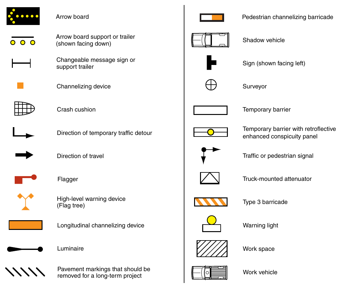
(Delaware Revision) Arrow board Pedestrian channelizing barricade Arrow board support or trailer (shown facing down) Shadow vehicle Changeable message sign or support trailer Sign (shown facing left) Channelizing device Surveyor Crash cushion Temporary barrier with retroflective enhanced conspicuity panel Traffic or pedestrian signal Flagger Truck-mounted attenuator High-level warning device (Flag tree) Type 3 barricade Longitudinal channelizing device Warning light Luminaire Work space Pavement markings that should be removed for a long-term project Work vehicle
Table 6P-3. Truck-Mounted Attenuator (TMA) Guideline for Planned Work Activity (Delaware Revision)
| Road Type | Speed | Time of Day | Shoulder Closure | Lane Closure | Paving & Milling Operations2 | ||||
|---|---|---|---|---|---|---|---|---|---|
| Work Zone Without Escape1 | Exposed Personnel | Non- Exposed Personnel | Work Zone Without Escape1 | Exposed Personnel | Non- Exposed Personnel | ||||
| Freeway or Expressway | ≥55 | Day | Required | Required | Required | Required | Required | Required | Recommended |
| ≥55 | Night | Required | Required | Required | Required | Required | Required | Recommended | |
| Non-Access Controlled Multi-Lane Roadways | ≥45 | Day | Required | Recommended | Recommended | Required | Required | Recommended | Recommended |
| ≥45 | Night | Required | Required | Recommended | Required | Required | Recommended | Recommended | |
| ≤40 | Day | Recommended | Recommended | Recommended | |||||
| ≤40 | Night | Recommended | Recommended | Recommended | |||||
| Two-Lane Roadways | ≥45 | Day | Required | Recommended | Required | Recommended | |||
| ≥45 | Night | Required | Recommended | Recommended | Required | Recommended | Recommended | ||
| ≤40 | Day | - | - | - | - | - | - | - | |
| ≤40 | Night | - | - | - | - | - | - | - | |
1 A work zone without escape may include such activities near or on a bridge structure. Work zones that exceed intermediate-term stationary durations shall reference the "Work Zone Safety & Mobility - Procedures and Guidelines" for additional guidance.
2 Paving and Milling operations are the primary functions and include work zone activities necessary to complete these activities. Roadway patching is not considered a paving and milling operation.
3 For less than 55 mph, see Non-Access Controlled Multi-Lane Roadways.
(Delaware Revision) NonSpeed of Work Zone & Milling NonExposed
01. A work zone without escape may include such activities near or on a bridge structure. Work zones that exceed intermediate-term stationary durations shall reference the "Work Zone Safety & Mobility - Procedures and Guidelines" for additional guidance.
02. Paving and Milling operations are the primary functions and include work zone activities necessary to complete these activities. Roadway patching is not considered a paving and milling operation.
03. For less than 55 mph, see Non-Access Controlled Multi-Lane Roadways. Notes for Figure 6P-1—Typical Application 1 (Delaware Revision)
Guidance
- 1. If the work space is in the median of a divided highway, an advance warning sign should also be placed on the left-hand side of the directional roadway.
- 2. Where drivers emerging from an intersecting roadway will not encounter an advance warning sign prior to the work zone, additional signs should be placed on the intersecting roadway.
Option
- 3. The ROAD WORK AHEAD sign may be replaced with other appropriate signs such as the SHOULDER WORK sign. The SHOULDER WORK sign may be used for work adjacent to the shoulder.
- 4. The ROAD WORK AHEAD sign may be omitted where the work space is behind a barrier, more than 24 inches behind the curb, or 15 feet or more from the edge of any roadway.
- 5. For short-term, short-duration or mobile operation, all signs and channelizing devices may be eliminated if a vehicle with activated high-intensity rotating, flashing, oscillating, or strobe lights is used.
- 6. Vehicle hazard warning signals may be used to supplement high-intensity rotating, flashing, oscillating, or strobe lights.
Standard
- 7. Vehicle hazard warning signals shall not be used instead of the vehicle’s high-intensity rotating, flashing, oscillating, or strobe lights.
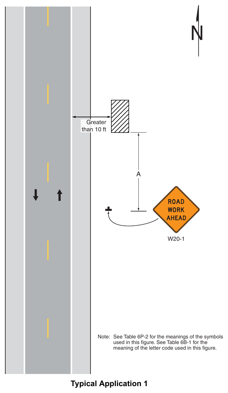
Signs shown: W20-1
(Delaware Revision) Greater than 10 ft Note: See Table 6P-2 for the meanings of the symbols used in this figure. See Table 6B-1 for the meaning of the letter code used in this figure. Typical Application 1 Notes for Figure 6P-1A—Typical Application 1A (Delaware Revision)
Guidance
- 1. Mowing operations should be performed during daylight hours only.
Standard
- 2. All equipment shall be stored in accordance with the Standard Construction Details
Guidance
- 3. The length of the work area should be limited to 2 miles or less.
- 4. Where drivers emerging from an intersecting roadway will not encounter an advance warning sign prior to the work zone, additional signs should be placed on the intersecting roadway.
Option
- 5. The MOWING AHEAD sign may be omitted where the work space is behind a barrier or 15 feet or more from the edge of any roadway.
- 6. For short-term, short duration or mobile operation, all signs and channelizing devices may be eliminated if a vehicle with activated high-intensity rotating, flashing, oscillating, or strobe lights is used.
- 7. Vehicle hazard warning signals may be used to supplement high-intensity rotating, flashing, oscillating, or strobe lights.
Standard
- 8. Vehicle hazard warning signals shall not be used instead of the vehicle’s high-intensity rotating, flashing, oscillating, or strobe lights.
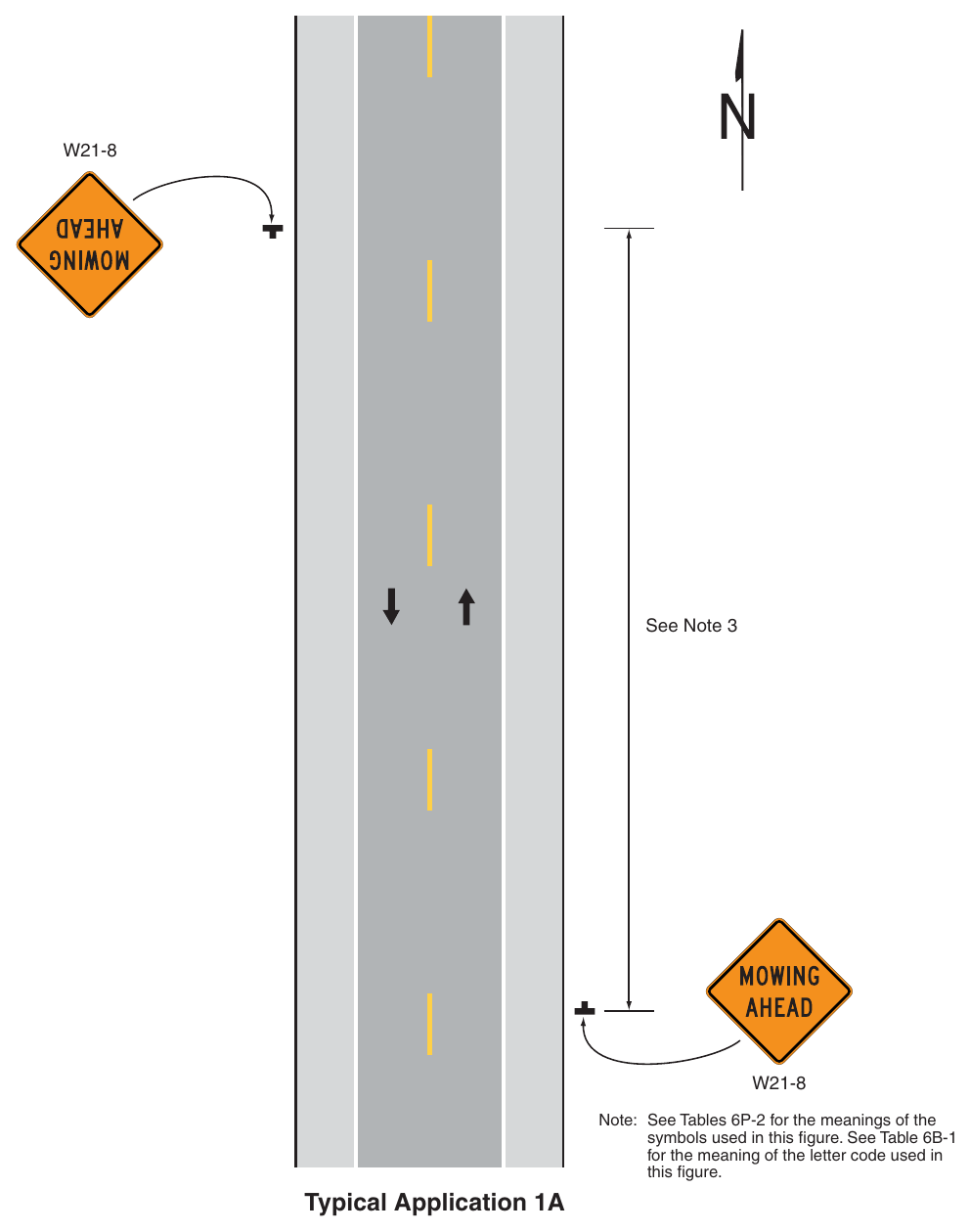
Signs shown: W21-8
(Delaware Revision) See Note 3 Note: See Tables 6P-2 for the meanings of the symbols used in this figure. See Table 6B-1 for the meaning of the letter code used in this figure. Typical Application 1A Notes for Figure 6P-1B—Typical Application 1B Mowing Operations along a Multi-Lane, Divided Highway (Delaware Revision)
Guidance
- 1. Mowing operations should be performed during daylight hours only.
Standard
- 2. All equipment shall be stored in accordance with the Standard Construction Details.
Guidance
- 3. The length of the work area should be limited to 2 miles or less.
- 4. Where drivers emerging from an intersecting roadway will not encounter an advance warning sign prior to the work zone, additional signs should be placed on the intersecting roadway.
Standard
- 5. When mowing operations occur within the median of a multi-lane, divided highway advance warning signs shall be placed on the median side of the roadway facing the direction of travel affected by the operation.
- 6. When mowing operations occur along the right-side only of a multi-lane highway, advance warning signs shall be placed on the right side of the roadway in the direction of the mowing operation.
Option
- 7. Advance warning signs may be omitted from the opposing direction when mowing operations in the median of a multi-lane, divided highway occur behind median barrier or when the median width is 50 feet or greater.
- 8. The MOWING AHEAD sign may be omitted where the work space is behind a barrier or 15 feet or more from the edge of any roadway.
- 9. For short-term, short duration or mobile operation, all signs and channelizing devices may be eliminated if a vehicle with activated high-intensity rotating, flashing, oscillating, or strobe lights is used.
- 10. Vehicle hazard warning signals may be used to supplement high-intensity rotating, flashing, oscillating, or strobe lights.
Standard
- 11. Vehicle hazard warning signals shall not be used instead of the vehicle’s high-intensity rotating, flashing, oscillating, or strobe lights.
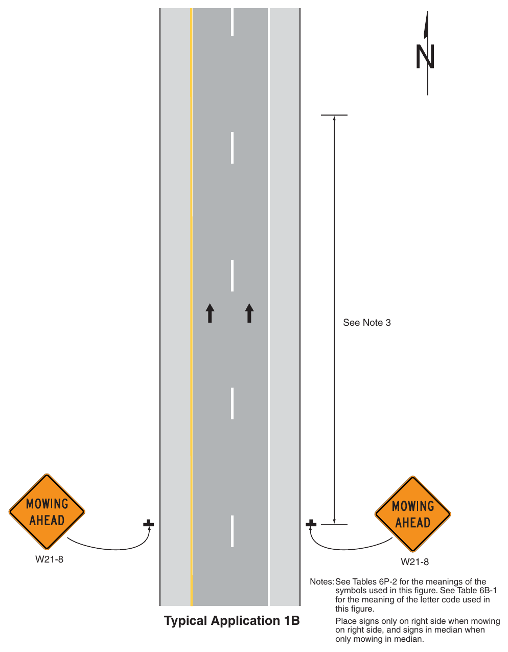
Signs shown: W21-8
(Delaware Revision) See Note 3 Typical Application 1B Notes: See Tables 6P-2 for the meanings of the symbols used in this figure. See Table 6B-1 for the meaning of the letter code used in this figure. Place signs only on right side when mowing on right side, and signs in median when only mowing in median. Notes for Figure 6P-2—Typical Application 2 (Delaware Revision)
Standard
- 1. Whenever blasting caps are used within 1,000 feet of a roadway, the signing shown shall be used.
- 2. The signs shall be covered or removed when there are no explosives in the area or the area is otherwise secure.
- 3. Whenever a side road intersects the roadway between the BLASTING ZONE AHEAD sign and the END BLASTING ZONE sign, or a side road is within 1,000 feet of any blasting cap, similar signing, as on the mainline, shall be installed on the side road.
- 4. Prior to blasting, the blaster in charge shall determine whether road users in the blasting zone will be endangered by the blasting operation. If there is danger, road users shall not be permitted to pass through the blasting zone during blasting operations.
Guidance
- 5. On a multi-lane, divided highway, the signs should be mounted on both sides of the directional roadways.
Option
- 6. The TURN OFF 2-WAY RADIO AND CELL PHONE (R22-2) sign may be omitted if the blasting operation does not incorporate the use of electric blasting caps.
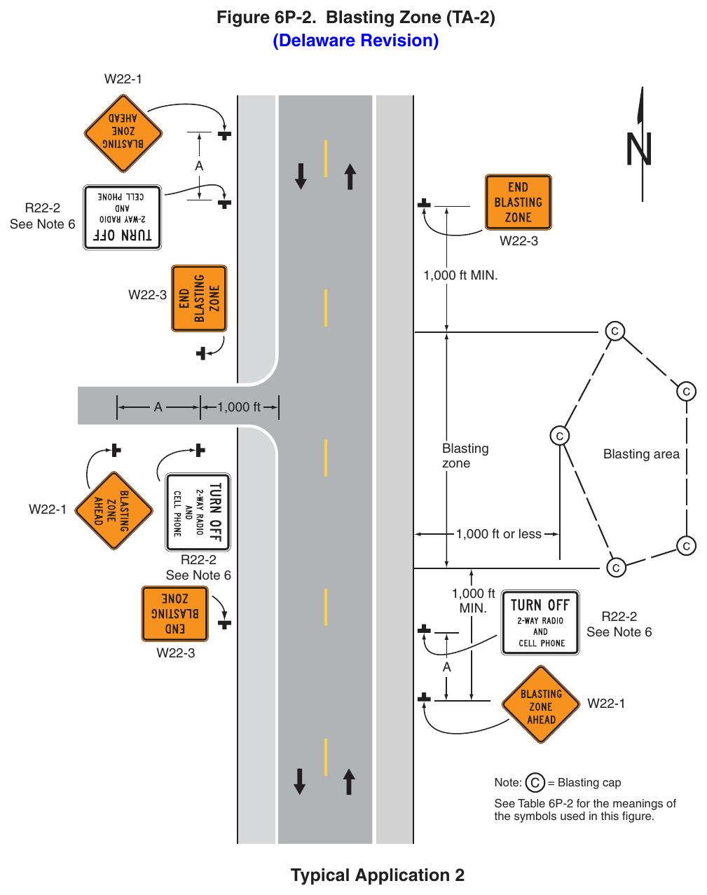
(Delaware Revision) See Note 6 1,000 ft MIN. 1,000 ft Blasting area 1,000 ft or less See Note 6 1,000 ft See Note 6 Note: = Blasting cap See Table 6P-2 for the meanings of the symbols used in this figure. Typical Application 2 Notes for Figure 6P-3—Typical Application 3 Work on the Shoulder of a Two-Lane Road (Delaware Revision)
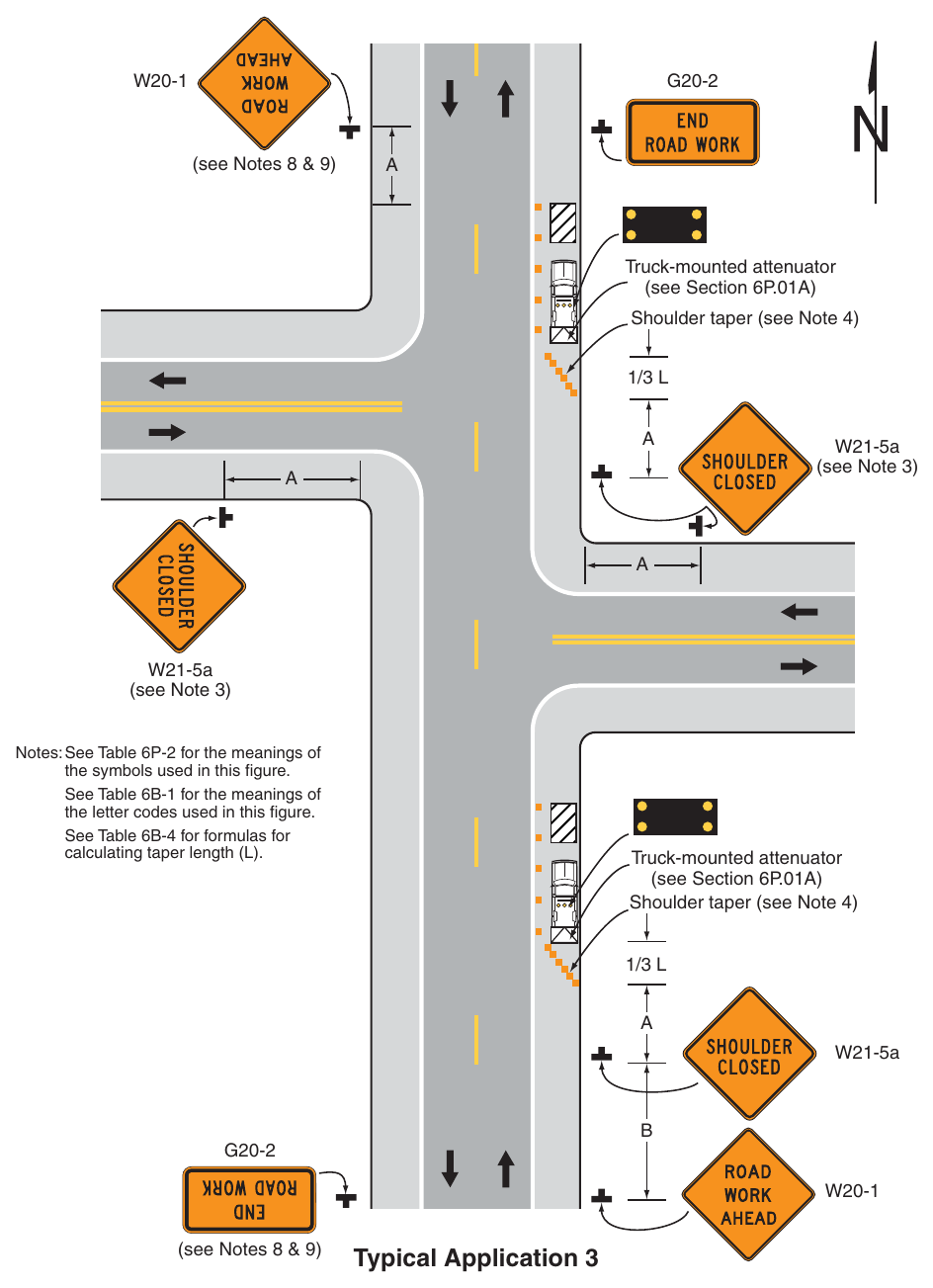
Guidance
- 1. A SHOULDER CLOSED sign should be placed on the left-hand side of the roadway for a divided or one-way street only if the left-hand shoulder is affected.
Option
- 2. Positive protection devices may be used per Section 6M.02.
- 3. The SHOULDER CLOSED sign on an intersecting roadway may be omitted where drivers emerging from that roadway will encounter another advance warning sign prior to this activity area.
- 4. For short-duration operations of 60 minutes or less, all signs and channelizing devices may be eliminated if a vehicle with activated high-intensity rotating, flashing, oscillating, or strobe lights is used.
- 5. Vehicle hazard warning signals may be used to supplement high-intensity rotating, flashing, oscillating, or strobe lights.
Standard
- 6. Vehicle hazard warning signals shall not be used instead of the vehicle’s high-intensity rotating, flashing, oscillating, or strobe lights.
- 7. When paved shoulders having a width of 8 feet or more are closed, at least one advance warning sign shall be used. In addition, channelizing devices shall be used to close the shoulder in advance to delineate the beginning of the work space and to direct vehicular traffic to remain within the
- 8. If the shoulder closure is located within a passing zone, ROAD WORK AHEAD and END ROAD WORK signs shall be placed for traffic approaching in the opposite direction.
Option
- 9. If the shoulder closure is located within a no-passing zone, ROAD WORK AHEAD and END ROAD WORK signs may be placed for traffic approaching in the opposite direction based on engineering judgement.
Guidance
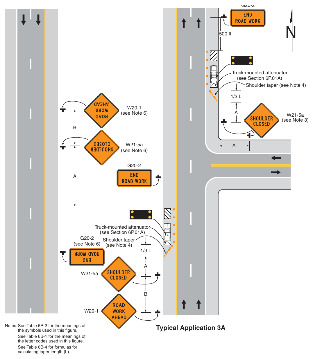
- 1. A SHOULDER CLOSED sign should be placed on the left-hand side of the roadway for a divided or one-way street only if the left-hand shoulder is affected.
Option
- 2. Positive protection devices may be used per Section 6M.02.
- 3. The SHOULDER CLOSED sign on an intersecting roadway may be omitted where drivers emerging from that roadway will encounter another advance warning sign prior to this activity area.
- 4. For short duration operations of 60 minutes or less, all signs and channelizing devices may be eliminated if a vehicle with activated high-intensity rotating, flashing, oscillating, or strobe lights is used.
- 5. Vehicle hazard warning signals may be used to supplement high-intensity rotating, flashing, oscillating, or strobe lights.
- 6. When work is occurring in the median of a divided roadway and the work location is located more than 10 feet from a travel lane, the ROAD WORK AHEAD, SHOULDER CLOSED, and END ROAD WORK warning signs may be omitted from the opposing direction.
Standard
- 7. Vehicle hazard warning signals shall not be used instead of the vehicle’s high-intensity rotating, flashing, oscillating, or strobe lights.
- 8. When paved shoulders having a width of 8 feet or more are closed, at least one advance warning sign shall be used. In addition, channelizing devices shall be used to close the shoulder in advance to delineate the beginning of the work space and to direct vehicular traffic to remain within the
Guidance
- 1. In those situations where multiple work locations within a limited distance make it practicable to place stationary signs, the distance between the advance warning sign and the work should not exceed 5 miles.
- 2. In those situations where the distance between the advance signs and the work is 2 miles to 5 miles, a Supplemental Distance plaque should be used with the ROAD WORK AHEAD sign.
- 3. Where drivers emerging from an intersecting roadway will not encounter the shadow vehicle prior to the work area, a stationary warning sign should be placed on the intersecting roadway.
Option
- 4. Additional positive protection devices may be used per Section 6M.02.
- 5. The ROAD WORK NEXT XX MILES sign may be used instead of the ROAD WORK AHEAD sign if the work locations occur over a distance of more than 2 miles.
- 6. Stationary warning signs may be omitted for short-duration or mobile operations if the work vehicle displays high-intensity rotating, flashing, oscillating, or strobe lights.
- 7. Vehicle hazard warning signals may be used to supplement high-intensity rotating, flashing, oscillating, or strobe lights.
Standard
- 8. Vehicle hazard warning signals shall not be used instead of the vehicle’s high-intensity rotating, flashing, oscillating, or strobe lights.
- 9. If an arrow board is used for an operation on the shoulder, the caution mode shall be used.
- 10. Vehicle-mounted signs shall be mounted in a manner such that they are not obscured by equipment or supplies. Sign legends on vehicle-mounted signs shall be covered or turned from view when work is not in progress.
Guidance
- 11. Where adequate stopping sight distance exists to the rear, the shadow vehicle should maintain the minimum distance from the work vehicle and proceed at the same speed. The shadow vehicle should slow in advance of vertical and horizontal curves that restrict sight distance.
Option
- 12. The minimum distance between the work and shadow vehicles may vary according to the terrain and the manufacturer’s recommendations for the truck-mounted attenuator.
- 13. If a work vehicle cannot support the installation of an arrow board, a trailer mounted arrow board may be used.
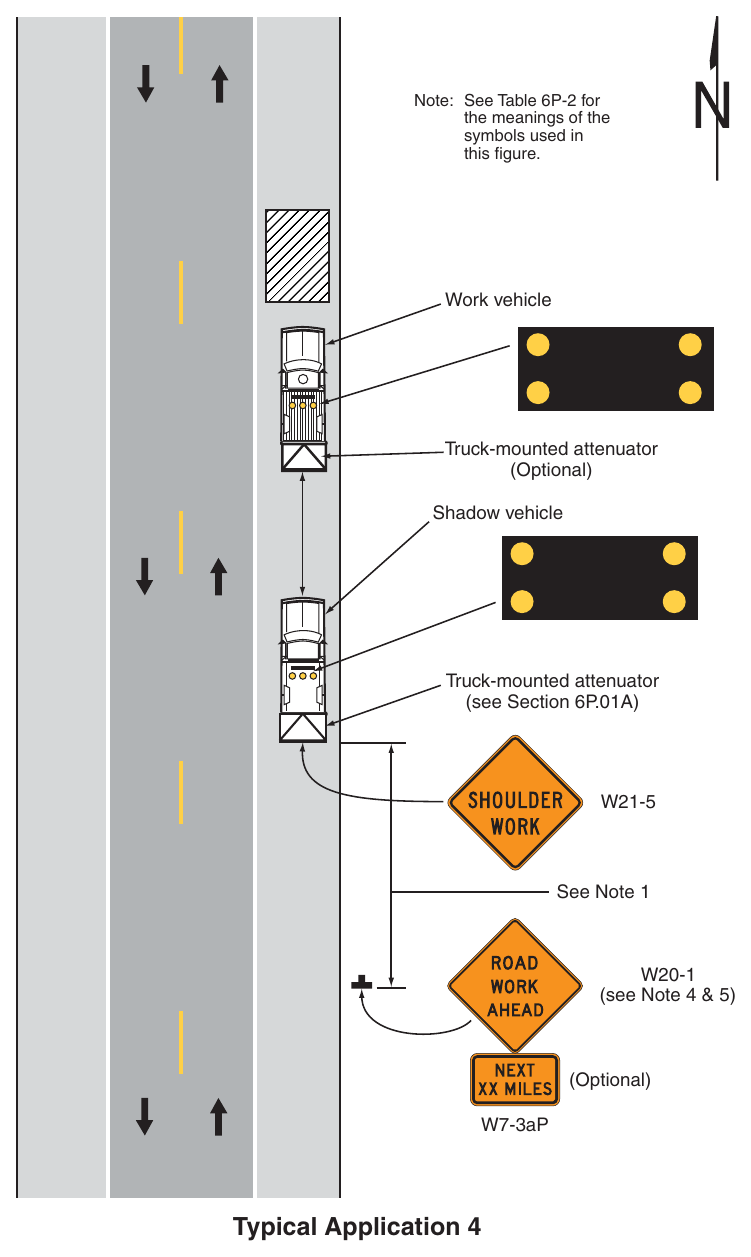
(Delaware Revision) Note: See Table 6P-2 for the meanings of the symbols used in this figure. Work vehicle Truck-mounted attenuator (Optional) Shadow vehicle Truck-mounted attenuator (see Section 6P.01A) See Note 1 (see Note 4 & 5) (Optional) W7-3aP Typical Application 4 Notes for Figure 6P-5—Typical Application 5 (Delaware Revision)
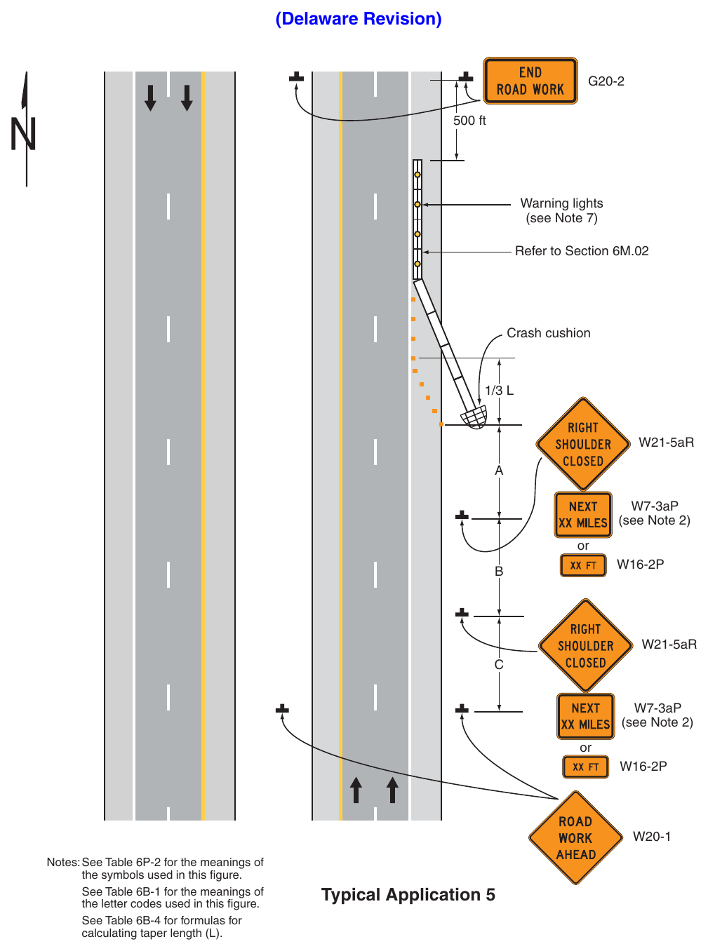
Guidance
- 1. RIGHT (LEFT) SHOULDER CLOSED signs should be used on limited-access highways where there is no opportunity for disabled vehicles to pull off the roadway.
- 2. If drivers cannot see a pull-off area beyond the closed shoulder, information regarding the length of the shoulder closure should be provided in feet or miles, as appropriate.
- 3. Where drivers emerging from an intersecting roadway or entrance ramp will not encounter an advance warning sign prior to the work zone, additional signs should be placed on the intersecting roadway or
- 4. The use of a temporary traffic barrier should be based on engineering judgment.
Standard
- 5. Temporary traffic barriers, if used, shall comply with the provisions of Section 6M.02.
Option
- 6. The barrier shown in this typical application is an example of one method that may be used to close a shoulder of a long-term project.
- 7. Warning lights may be used to supplement temporary traffic barrier approved by DelDOT Traffic.
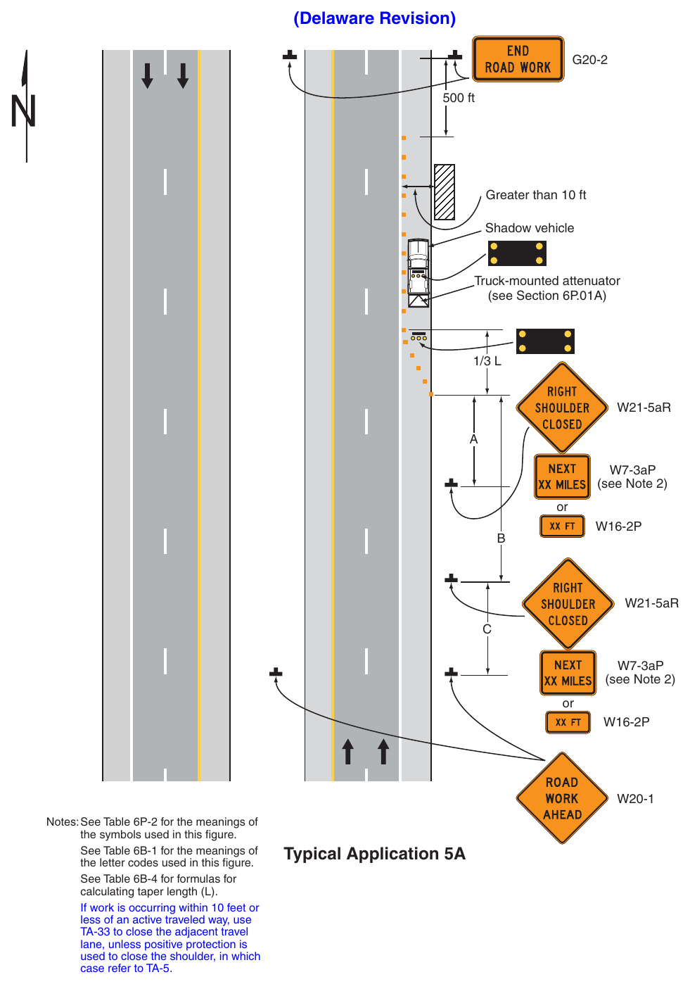
Guidance
- 1. RIGHT (LEFT) SHOULDER CLOSED signs should be used on limited-access highways where there is no opportunity for disabled vehicles to pull off the roadway.
- 2. If drivers cannot see a pull-off area beyond the closed shoulder, information regarding the length of the shoulder closure should be provided in feet or miles, as appropriate.
- 3. Where drivers emerging from an intersecting roadway or entrance ramp will not encounter an advance warning sign prior to the work zone, additional signs should be placed on the intersecting roadway or
Standard
- 4. When paved shoulders having a width of 8 feet or more are closed, at least one advance warning sign shall be used. In addition, channelizing devices shall be used to close the shoulder in advance to delineate the beginning of the work space and direct vehicular traffic to remain within the
- 5. Vehicle hazard warning signals shall not be used instead of the vehicle’s high-intensity rotating, flashing, oscillating, or strobe lights.
Option
- 6. Vehicle hazard warning signals may be used to supplement high-intensity rotating, flashing, oscillating, or strobe lights.
Guidance
- 7. If work is occurring 10 feet or less from an adjacent travel lane and positive protection is not used to separate the work space from the traffic space, the travel lane should be closed following Figure 6P-33.
Standard
- 1. This TTC zone application shall be limited to low-speed roads with a posted speed limit of 25 mph or less. For higher-speed traffic conditions, a lane closure shall be used (see Figure 6P-10).
Guidance
- 2. All lanes should be a minimum of 10 feet in width as measured to the near face of the channelizing devices. Except as provided in Note 5, a lane closure (see Figure 6P-10) should be used when the operations cannot accommodate the minimum 10-feet of travel lane.
Option
- 3. Additional positive protection devices may be used per Section 6M.02.
- 4. For short-term use on low-volume, low-speed roadways with vehicular traffic that does not include longer and wider heavy commercial vehicles, a minimum lane width of 9 feet may be used.
- 5. Where the opposite shoulder is suitable for carrying vehicular traffic and of adequate width, lanes may be shifted by use of closely-spaced channelizing devices, provided that the minimum lane width of 10 feet is maintained (see Figure 6P-11B).
- 6. Additional advance warning may be appropriate, such as a ROAD NARROWS sign.
- 7. Temporary traffic barriers may be used along the work space.
- 8. The shadow vehicle may be omitted if a taper and channelizing devices are used.
- 10. For short-duration work, the taper and channelizing devices may be omitted if a shadow vehicle with activated high-intensity rotating, flashing, oscillating, or strobe lights is used.
- 11. Vehicle hazard warning signals may be used to supplement high-intensity rotating, flashing, oscillating, or strobe lights.
Standard
- 12. Vehicle-mounted signs shall be mounted in a manner such that they are not obscured by equipment or supplies. Sign legends on vehicle-mounted signs shall be covered or turned from view when work is not in progress.
- 13. Shadow and work vehicles shall display high-intensity rotating, flashing, oscillating, or strobe lights.
- 14. Vehicle hazard warning signals shall not be used instead of the vehicle’s high-intensity rotating, flashing, oscillating, or strobe lights.
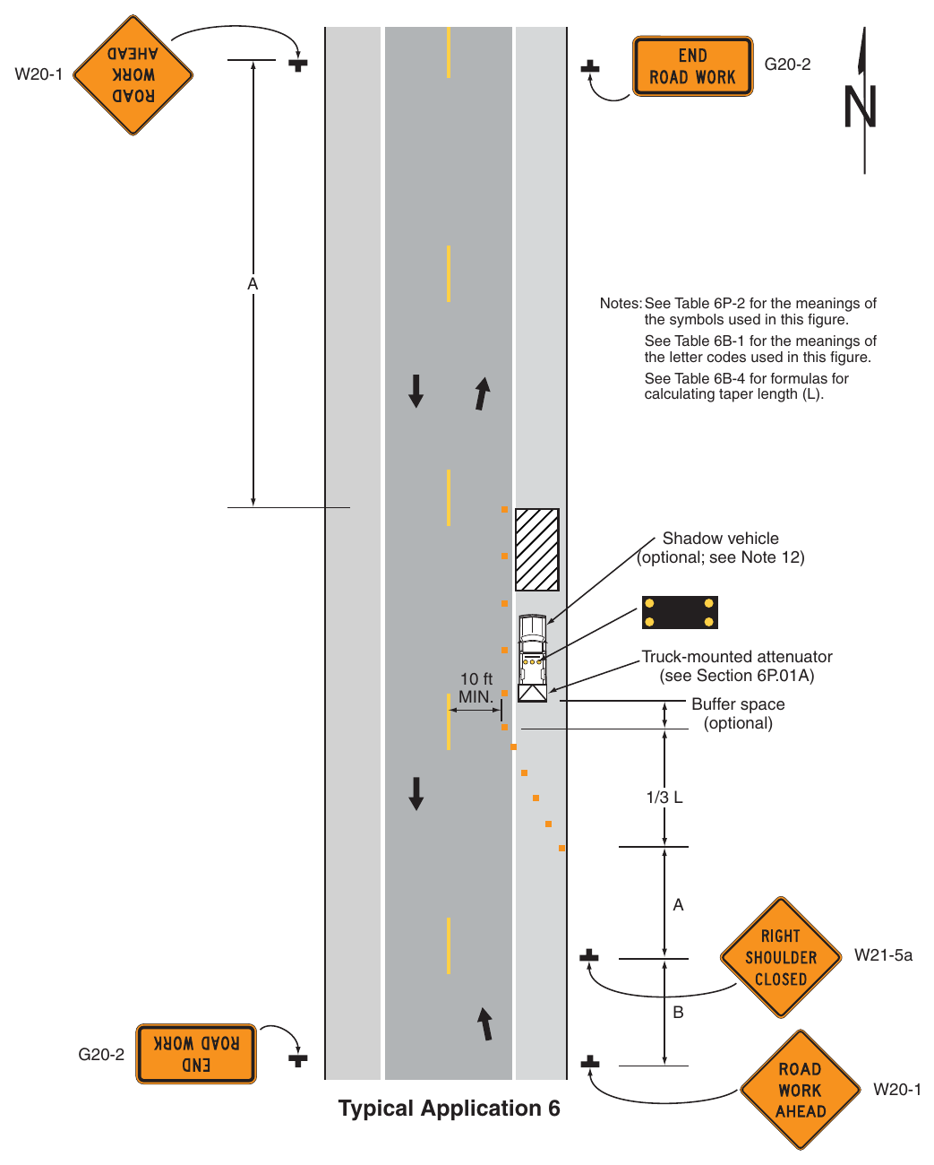
(Delaware Revision) Notes: See Table 6P-2 for the meanings of the symbols used in this figure. See Table 6B-1 for the meanings of the letter codes used in this figure. See Table 6B-4 for formulas for calculating taper length (L). Shadow vehicle (optional; see Note 12) 10 ft Truck-mounted attenuator (see Section 6P.01A) Buffer space (optional) W21-5a Typical Application 6 Notes for Figure 6P-7—Typical Application 7 (Delaware Revision)
Support
- 1. Signs and object markers are shown for one direction of travel only.
Standard
- 2. Devices similar to those depicted shall be placed for the opposite direction of travel.
- 3. Pavement markings no longer applicable to the traffic pattern of the roadway shall be removed or obliterated before any new traffic patterns are open to traffic.
- 4. Temporary traffic barriers and end treatments shall be crashworthy.
Guidance
- 5. A shifting taper length of L is preferred on state-maintained roads (see Tables 6B-3 and 6B-4).
- 6. If the tangent distance along the temporary diversion is more than 600 feet, a Reverse Curve sign should be used instead of the Double Reverse Curve sign, and a second Reverse Curve sign should be placed in advance of the second reverse curve back to the original alignment.
- 7. When the tangent section of the diversion is more than 600 feet, and the diversion has sharp curves with recommended speeds of 30 mph or less, Reverse Turn signs should be used.
- 8. Where the temporary pavement and old pavement are different colors, the temporary pavement should start on the tangent of the existing pavement and end on the tangent of the existing pavement.
- 9. Advisory Speed plaques should be used only when the advisory speed is less than the posted speed limit.
Option
Flashing warning lights and/or flags may be used to call attention to the warning signs.
- 10. On sharp curves, large arrow signs may be used in addition to other advance warning signs.
- 11. Delineators or channelizing devices may be used along the diversion.
- 12. Changes in alignment may be accomplished using horizontal curves designed for normal highway speeds in accordance with the DelDOT Road Design Manual.
- 13. Shift areas may be illuminated at night.
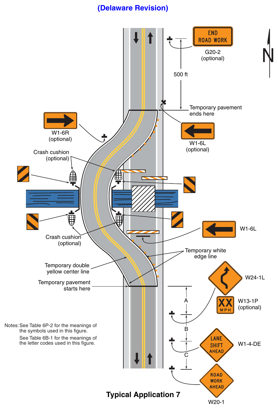
Signs shown: G20-2, W1-6R, W1-6L, W24-1L, W13-1P, W1-4, W20-1
(Delaware Revision) (optional) 500 ft Temporary pavement ends here (optional) (optional) Crash cushion (optional) Crash cushion (optional) Temporary white edge line yellow center line Temporary pavement starts here Notes: See Table 6P-2 for the meanings of the symbols used in this figure. See Table 6B-1 for the meanings of the letter codes used in this figure. (optional) Typical Application 7 Notes for Figure 6P-8—Typical Application 8 (Delaware Revision)
Standard
- 1. All detours affecting state-maintained roadways shall have a detour plan approved by DelDOT Traffic.
- 2. Before a road is closed to traffic, all necessary detour signs shall be in place along the corresponding detour route.
- 3. Type 3 Barricades used at the point of the road closure shall extend entirely across the closed portion of the roadway, including corresponding shoulders, in accordance with Section 6K.07.
- 4. Devices similar to those depicted shall be placed for the opposite direction of travel.
Guidance
- 5. Regulatory traffic control devices should be modified as needed for the duration of the detour.
Option
- 6. If the road is opened for some distance beyond the intersection and/or there are significant origin/ destination points beyond the intersection, the ROAD CLOSED and DETOUR signs on Type 3 Barricades may be located at the edge of the traveled way.
- 7. A Route Sign Directional assembly may be placed on the far left corner of the intersection to augment or replace the one shown on the near right corner.
- 8. Flashing warning lights and/or flags may be used to call attention to the advance warning signs.
- 9. Cardinal direction plaques may be used with route signs.
Support
- 10. Refer to Typical Application 20 for placement of detour signage along the detour route.
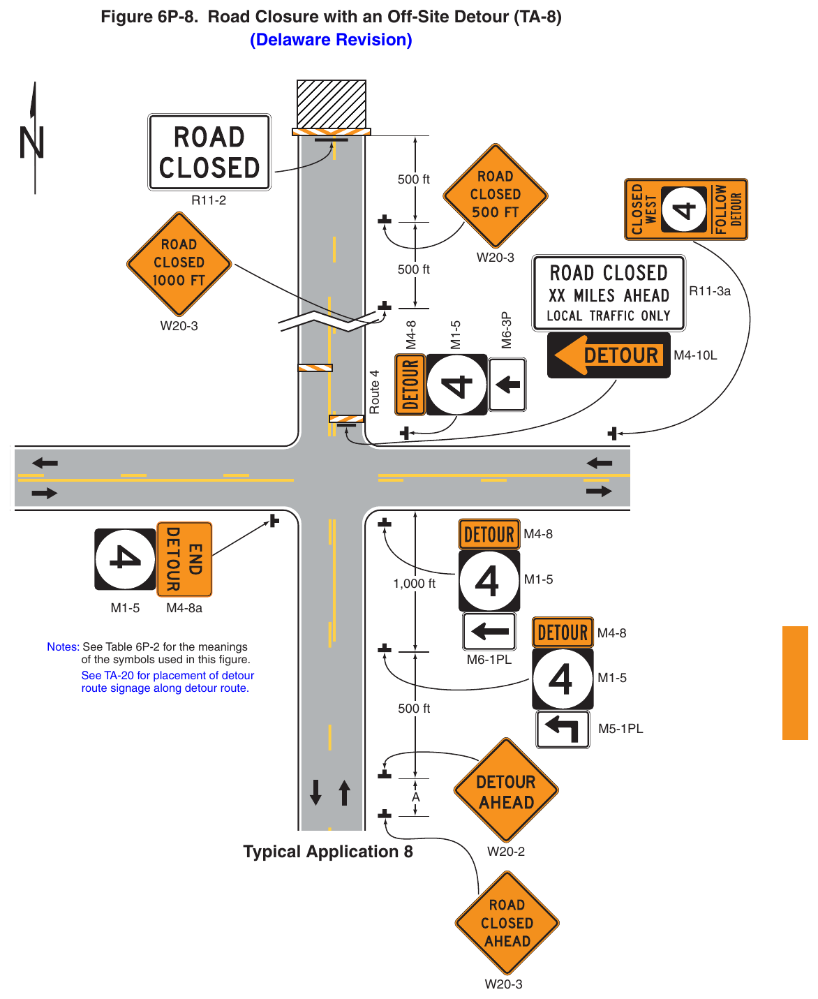
Signs shown: R11-2, W20-3, R11-3a, M4-10L, M4-8, M1-5, M4-8a, W20-2
(Delaware Revision) 500 ft 500 ft Route 4 R11-3a 1,000 ft M4-8a Notes: See Table 6P-2 for the meanings of the symbols used in this figure. See TA-20 for placement of detour route signage along detour route. 500 ft Typical Application 8 Notes for Figure 6P-9—Typical Application 9 (Delaware Revision)
Support
- 1. TTC devices are shown for one direction of travel only.
Standard
- 2. All detours affecting state-maintained roadways shall have a detour plan approved by DelDOT Traffic.
- 3. Before a road is closed to traffic, all necessary detour signs shall be in place along the corresponding detour route.
- 4. Type 3 Barricades used at the point of the road closure shall extend entirely across the closed portion of the roadway, including corresponding shoulders, in accordance with Section 6K.07.
- 5. Devices similar to those depicted shall be placed for the opposite direction of travel.
Guidance
- 6. STOP or YIELD signs displayed to side roads should be installed as needed along the temporary route.
Option
- 7. Flashing warning lights and/or flags may be used to call attention to the advance warning signs.
- 8. Flashing warning lights may be used on the Type 3 Barricades.
- 9. Cardinal direction plaques may be used with route signs.
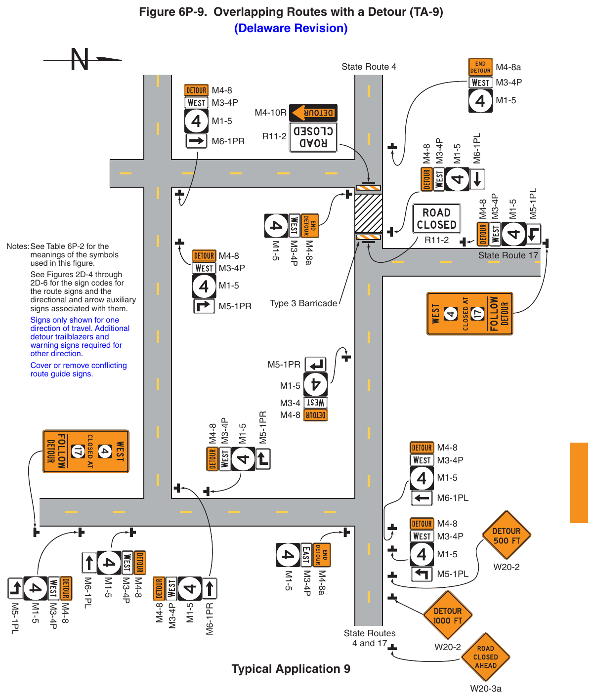
Signs shown: M4-8, M3-4P, M4-10R, M1-5, R11-2, W20-2, M4-8a, W20-3a, M3-4
(Delaware Revision) State Route 4 M4-8a Notes: See Table 6P-2 for the meanings of the symbols used in this figure. See Figures 2D-4 through 2D-6 for the sign codes for the route signs and the directional and arrow auxiliary signs associated with them. Signs only shown for one direction of travel. Additional detour trailblazers and warning signs required for Cover or remove conflicting route guide signs. M4-8a State Route 17 Type 3 Barricade M4-8a State Routes 4 and 17 Typical Application 9 W20-3a Notes for Figure 6P-10—Typical Application 10 Lane Closure on a Two-Lane Road Using Flaggers (Delaware Revision)
Option
- 1. Positive protection devices may be used per Section 6M.02.
- 2. For low-volume situations with short TTC zones on straight roadways where the flagger is visible to road users approaching from both directions, a single flagger, positioned to be visible to road users approaching from both directions, may be used (see Chapter 6D).
- 3. The ROAD WORK AHEAD and the END ROAD WORK signs may be omitted for short-duration A BE PREPARED TO STOP sign may be added to the sign series.
- 5. Automated Flagger Assistance Devices (see Section 6L.02) may be used in situations where there is only one lane of approaching traffic in the direction to be controlled.
Guidance
- 6. The buffer space should be extended so that the two-way traffic taper is placed before a horizontal (or crest vertical) curve to provide adequate sight distance for the flagger and a queue of stopped vehicles.
Standard
- 7. At night, flagger stations shall be illuminated, except in emergencies.
Guidance
- 8. When used, the BE PREPARED TO STOP sign should be located between the Flagger sign and the ONE LANE ROAD sign.
- 9. Where drivers emerging from an intersecting roadway will not encounter an advance warning sign prior to the work zone, additional signs should be placed on the intersecting roadway.
- 10. When a grade crossing exists within or upstream of the transition area and it is anticipated that queues resulting from the lane closure might extend through the grade crossing, the TTC zone should be extended so that the transition area precedes the grade crossing.
- 11. When a grade crossing equipped with active warning devices exists within the activity area, provisions should be made for keeping flaggers informed as to the activation status of these warning devices.
- 12. When a grade crossing exists within the activity area, drivers operating on the left-hand side of the normal center line should be provided with comparable warning devices as for drivers operating on the right-hand side of the normal center line.
- 13. Early coordination with the railroad company or transit agency should occur before work starts.
Option
- 14. A flagger or a uniformed law enforcement officer may be used at the grade crossing to minimize the probability that vehicles are stopped within 15 feet of the grade crossing, measured from both sides of the outside rails.
Guidance
- 15. Where multiple crews are working and separated by 1,000 feet or more, a truck-mounted attenuator should be used to shadow each work crew.
- 16. Where a side road or major access point, such as a commercial, industrial, or subdivision entrance intersects the work zone, additional flagger(s) should be located in the vicinity of the intersection(s).
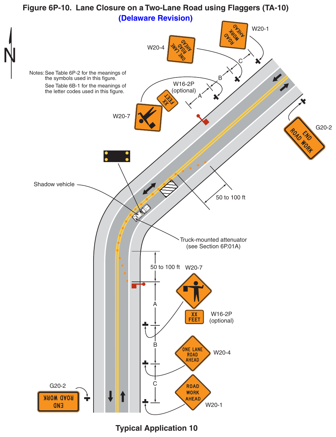
(Delaware Revision) Notes: See Table 6P-2 for the meanings of the symbols used in this figure. See Table 6B-1 for the meanings of the letter codes used in this figure. (optional) Shadow vehicle 50 to 100 ft Truck-mounted attenuator (see Section 6P.01A) 50 to 100 ft W20-7 (optional) Typical Application 10 Notes for Figure 6P-11—Typical Application 11 Lane Closure on a Two-Lane Road with Low Traffic Volumes Using a YIELD Sign (Delaware Revision)
Option
- 1. Positive protection devices may be used per Section 6M.02.
- 2. This TTC zone application may be used as an alternate to the TTC application shown in Figure 6P-10 (using flaggers) when the following conditions exist:
- a. Vehicular traffic volume is such that sufficient gaps exist for vehicular traffic that must yield.
- b. Road users from both directions are able to see approaching vehicular traffic through and beyond the worksite and have sufficient visibility of approaching vehicles.
- 3. A YIELD sign and yield line pavement marking may be used on approaches to the work zone.
Standard
- 4. This TTC zone application shall require approval from DelDOT Traffic.
Guidance
- 5. Where drivers emerging from an intersecting roadway will not encounter an advance warning sign prior to the work zone, additional signs should be placed on the intersecting road and all-way stop control or temporary traffic control signals should be considered (see Figures 6P-11A and 6P-12).
- 6. All lanes should be a minimum of 10 feet in width as measured to the edge line or near face of the channelizing devices. Except as provided in note 11 a flagger-controlled lane closure (see Figure 6P-10) should be used when the operations cannot accommodate the minimum 10-foot travel lane.
- 7. A yield line should be installed on the yield-controlled approach for long-term and intermediate-term closures. Existing conflicting pavement markings and raised pavement marker reflectors within the transition and activity area should be removed.
- 8. Where no-passing lines are not already in place, they should be added.
Option
- 9. For short-term use on low-volume, low-speed roadways with vehicular traffic that does not include longer and wider heavy commercial vehicles, a minimum lane width of 9 feet may be used.
- 10. Removable pavement markings may be used.
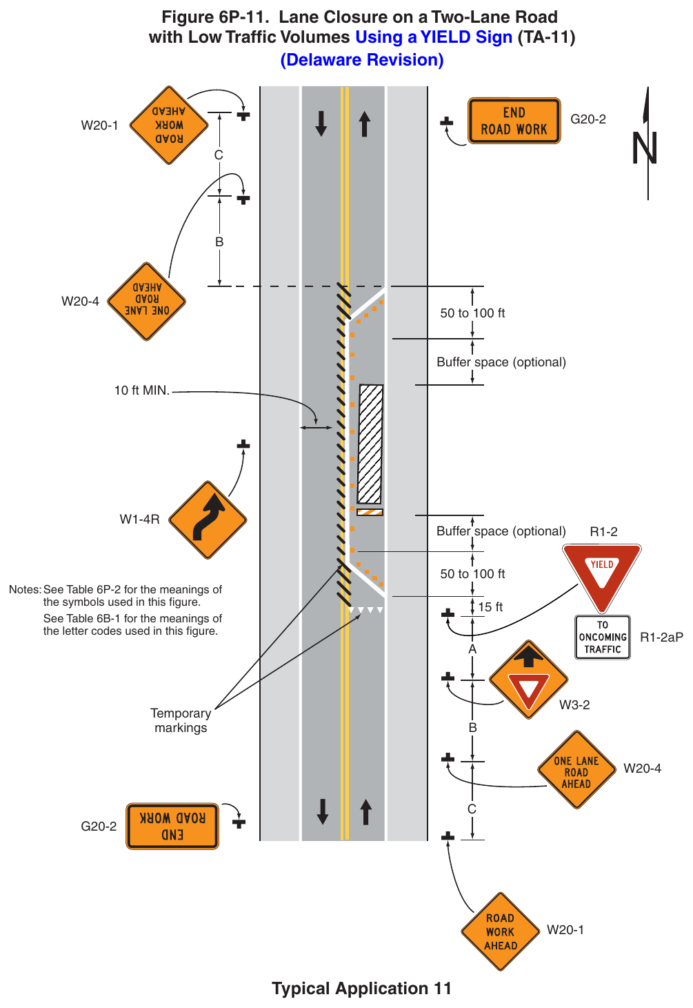
with Low Traffic Volumes Using a YIELD Sign (TA-11) (Delaware Revision) 50 to 100 ft Buffer space (optional) 10 ft MIN. Buffer space (optional) 50 to 100 ft Notes: See Table 6P-2 for the meanings of the symbols used in this figure. See Table 6B-1 for the meanings of the letter codes used in this figure. 15 ft R1-2aP markings Typical Application 11 Notes for Figure 6P-11A —Typical Application 11A Lane Closure on a Two-Lane Road with Low Traffic Volumes Using STOP Signs (Delaware Revision)
Option
- 1. Positive protection devices may be used per Section 6M.02.
- 2. This TTC zone application may be used as an alternate to the TTC application shown in Figure 6P-10 (using flaggers) when the following conditions exist:
- a. Vehicular traffic volume is such that sufficient gaps exist for vehicular traffic that must stop.
- b. Road users from both directions are able to see approaching vehicular traffic through and beyond the worksite and have sufficient visibility of approaching vehicles.
Standard
- 3. This TTC zone application affecting state-maintained roadways shall require approval from DelDOT Traffic.
Guidance
- 4. Where drivers emerging from an intersecting roadway will not encounter an advance warning sign prior to the work zone, additional signs should be placed on the intersecting road.
- 5. All lanes should be a minimum of 10 feet in width as measured to the edge line or near face of the channelizing devices. Except as provided in note 10 a flagger-controlled lane closure (see Figure 6P-10) should be used when the operations cannot accommodate the minimum 10-foot travel lane.
- 6. Stop lines should be installed for long-term and intermediate-term closures. Existing conflicting pavement markings and raised pavement marker reflectors within the transition and activity areas should be removed.
- 7. Where no-passing lines are not already in place, they should be added.
Option
- 8. For short-term use on low-volume, low-speed roadways with vehicular traffic that does not include longer and wider heavy commercial vehicles, a minimum lane width of 9 feet may be used.
- 9. Removable pavement markings may be used.
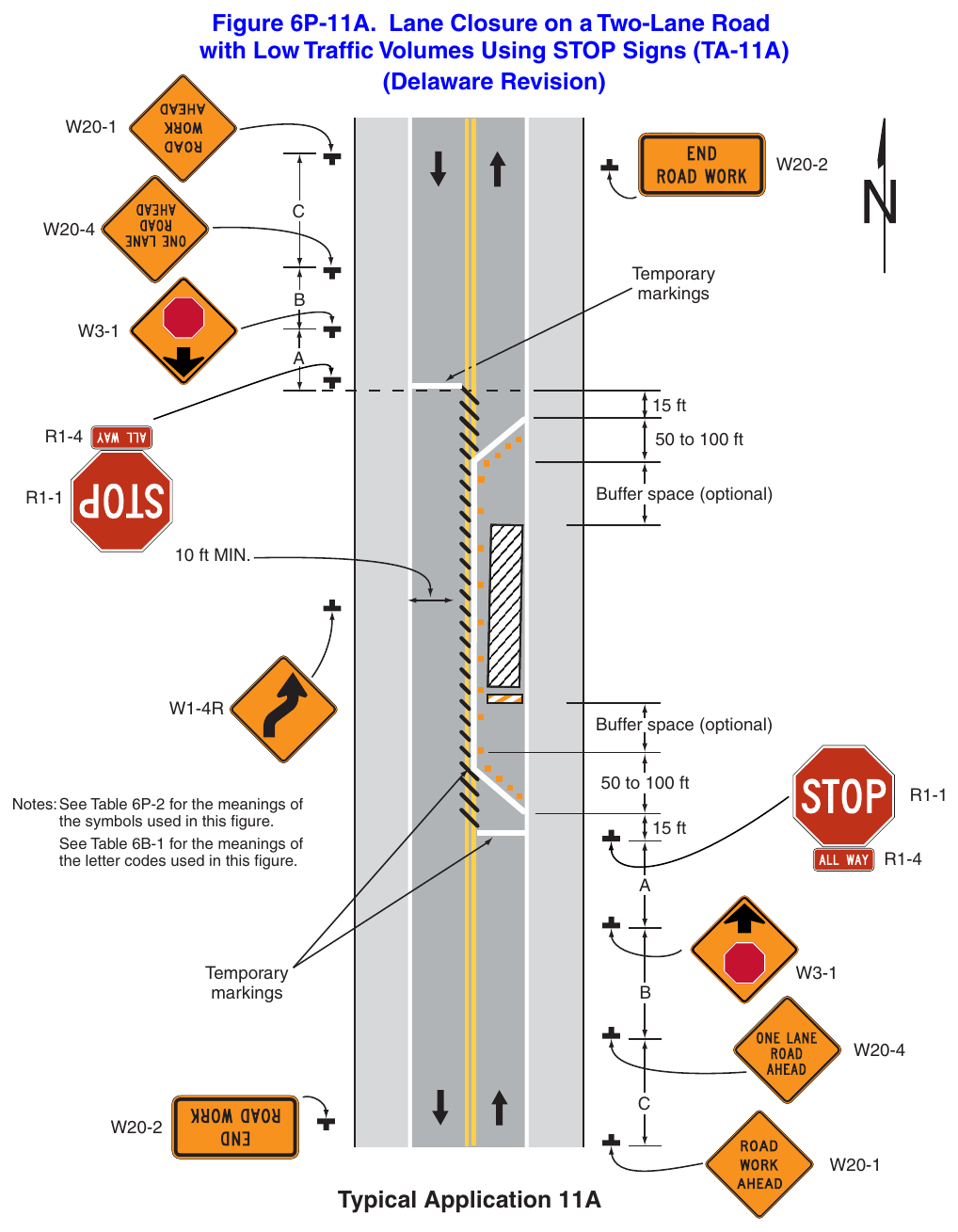
with Low Traffic Volumes Using STOP Signs (TA-11A) (Delaware Revision) markings 15 ft 50 to 100 ft Buffer space (optional) 10 ft MIN. Buffer space (optional) 50 to 100 ft Notes: See Table 6P-2 for the meanings of the symbols used in this figure. See Table 6B-1 for the meanings of the letter codes used in this figure. 15 ft markings Typical Application 11A Notes for Figure 6P-11B —Typical Application 11B (Delaware Revision)
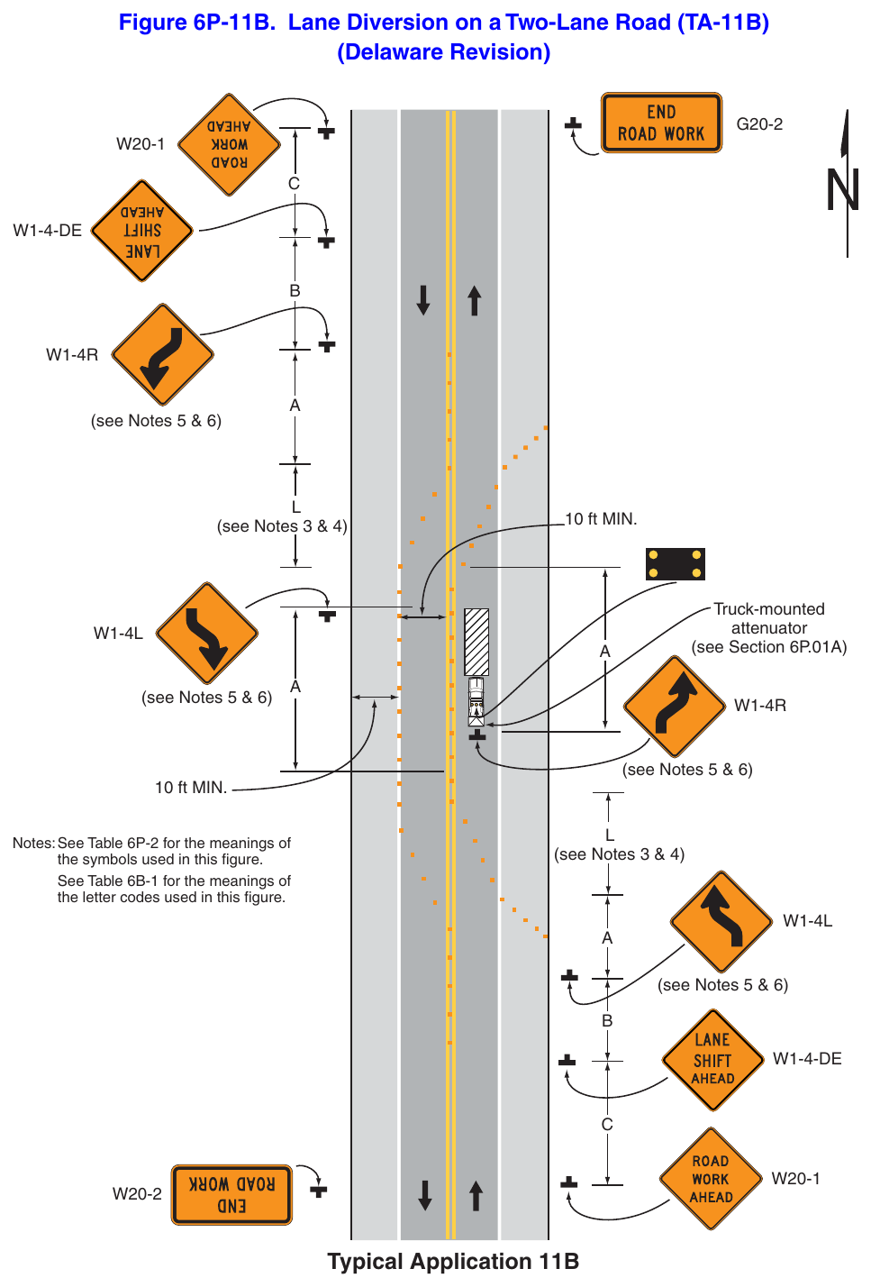
Option
- 1. Where the opposite shoulder is suitable for carrying vehicular traffic and of adequate width, lanes may be shifted.
Guidance
- 2. All lanes should be a minimum of 10 feet in width as measured to the near face of the channelizing devices. Except as provided in Note 14, a lane closure (see Figure 6P-10) should be used when the operations cannot accommodate the minimum 10-foot travel lane.
- 3. A shifting taper length of L is preferred on state-maintained roads (see Tables 6B-3 and 6B-4).
- 4. For roadways with a posted speed limit of 35 mph or greater, Reverse Curve signs should be used as shown in Figure 6P-11B. For roadways with a posted speed limit of 30 mph or less, Reverse Turn signs should be used instead of the Reverse Curve sign.
- 5. If the tangent distance along the temporary diversion is less than 600 feet, Double Reverse Curve (or Turn) signs should be used instead of the upstream Reverse Curve (or Turn) signs and the downstream Reverse Curve (or Turn) signs should be omitted.
- 6. Where drivers emerging from an intersecting roadway will not encounter an advance warning sign prior to the work zone, additional signs should be placed on the intersecting road.
- 7. For long-term operations, the shoulder pavement bearing capacity should be evaluated prior to using this Typical Application.
- 8. For long-term operations, existing longitudinal rumble strips should be removed or filled with an acceptable material anywhere the wheel paths would cross the rumble strips.
Standard
- 9. All conflicting pavement markings shall be removed and temporary markings shall be placed for long-term operations.
Option
- 10. For short-term use on low-speed, low-volume roadways with vehicular traffic that does not include longer and wider heavy commercial vehicles, a minimum lane width of 9 feet may be used.
- 11. For short-term daytime operations or intermediate-term nightly operations, channelizing devices and temporary warning signage may be used without removal of conflicting pavement markings and placement of temporary markings as long as all devices are removed at the end of each work shift.
- 12. Shift areas may be illuminated at night.
Standard
- 1. All temporary traffic control signals along state-maintained roadways shall have a signal plan approved by DelDOT Traffic.
- 2. Temporary traffic control signals shall be installed and operated in accordance with the provisions of Part 4. Temporary traffic control signals shall meet the physical display and operational requirements of conventional traffic control signals.
- 3. Temporary traffic control signal timing shall be established by authorized officials. Durations of red clearance intervals shall be adequate to clear the one-lane section of conflicting vehicles.
- 4. When the temporary traffic control signal is changed to the flashing mode, either manually or automatically, red signal indications shall be flashed to both approaches.
- 5. Stop lines shall be installed with temporary traffic control signals for long-term closures. Existing conflicting pavement markings and raised pavement marker reflectors between the activity area and each stop line shall be removed. After the temporary traffic control signal is removed, the stop lines and other temporary pavement markings shall be removed and the permanent pavement markings restored.
- 6. Safeguards shall be incorporated to avoid the possibility of conflicting signal indications at each end of the TTC zone.
Guidance
- 7. The primary signal faces controlling vehicular traffic should be located overhead.
- 8. Where no-passing lines are not already in place, they should be added.
- 9. Adjustments in the location of the advance warning signs should be made as needed to accommodate the horizontal or vertical alignment of the roadway, recognizing that the distances shown for sign spacings are minimums. Adjustments in the height of the signal heads should be made as needed to conform to the vertical alignment.
- 10. All lanes should be a minimum of 10 feet in width as measured to the edge line or near face of the channelizing devices. Except as provided in Note 15, a flagger-controlled lane closure (see Figure 6P-10) should be used when the operations cannot accommodate the minimum 10-foot travel lane.
Option
- 11. Positive protection devices may be used per Section 6M.02.
Flashing warning lights shown on the ROAD WORK AHEAD and the ONE LANE ROAD AHEAD
- 12. Removable pavement markings may be used.
- 13. For short-term use on low-volume, low-speed roadways with vehicular traffic that does not include longer and wider heavy commercial vehicles, a minimum lane width of 9 feet may be used.
Support
- 14. Temporary traffic control signals are preferable to flaggers for long-term projects and other activities that would require flagging at night.
- 15. The maximum length of activity area for one-way operation under temporary traffic control signal control is determined by the capacity required to handle the peak demand.
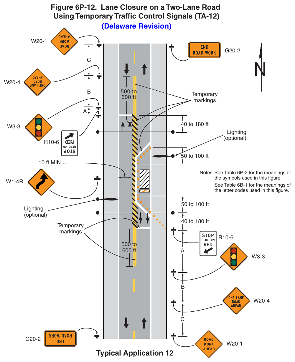
(Delaware Revision) 500 to 600 ft markings 40 to 180 ft Lighting (optional) 50 to 100 ft 10 ft MIN. Notes: See Table 6P-2 for the meanings of the symbols used in this figure. See Table 6B-1 for the meanings of the letter codes used in this figure. 50 to 100 ft Lighting (optional) 40 to 180 ft markings 500 to 600 ft Typical Application 12 Notes for Figure 6P-13—Typical Application 13 (Delaware Revision)
Support
- 1. Conditions represented are a planned closure not exceeding 20 minutes during off-peak hours.
Standard
- 2. A flagger or uniformed law enforcement officer shall be used for this application. The flagger, if used for this application, shall follow the procedures provided in Sections 6D.05 and 6D.06.
Guidance
- 3. The uniformed law enforcement officer, if used for this application, should follow the procedures provided in Sections 6D.05 and 6D.06.
Option
- 4. A BE PREPARED TO STOP sign may be added to the sign series.
- 5. Positive protection devices may be used per Section 6M.02.
- 6. Automated Flagger Assistance Devices (see Section 6L.02) may be used in situations where there is only one lane of approaching traffic in the direction to be controlled.
Guidance
- 7. When used, the BE PREPARED TO STOP sign should be located before the Flagger symbol sign.
Standard
- 8. At night, flagger stations shall be illuminated.
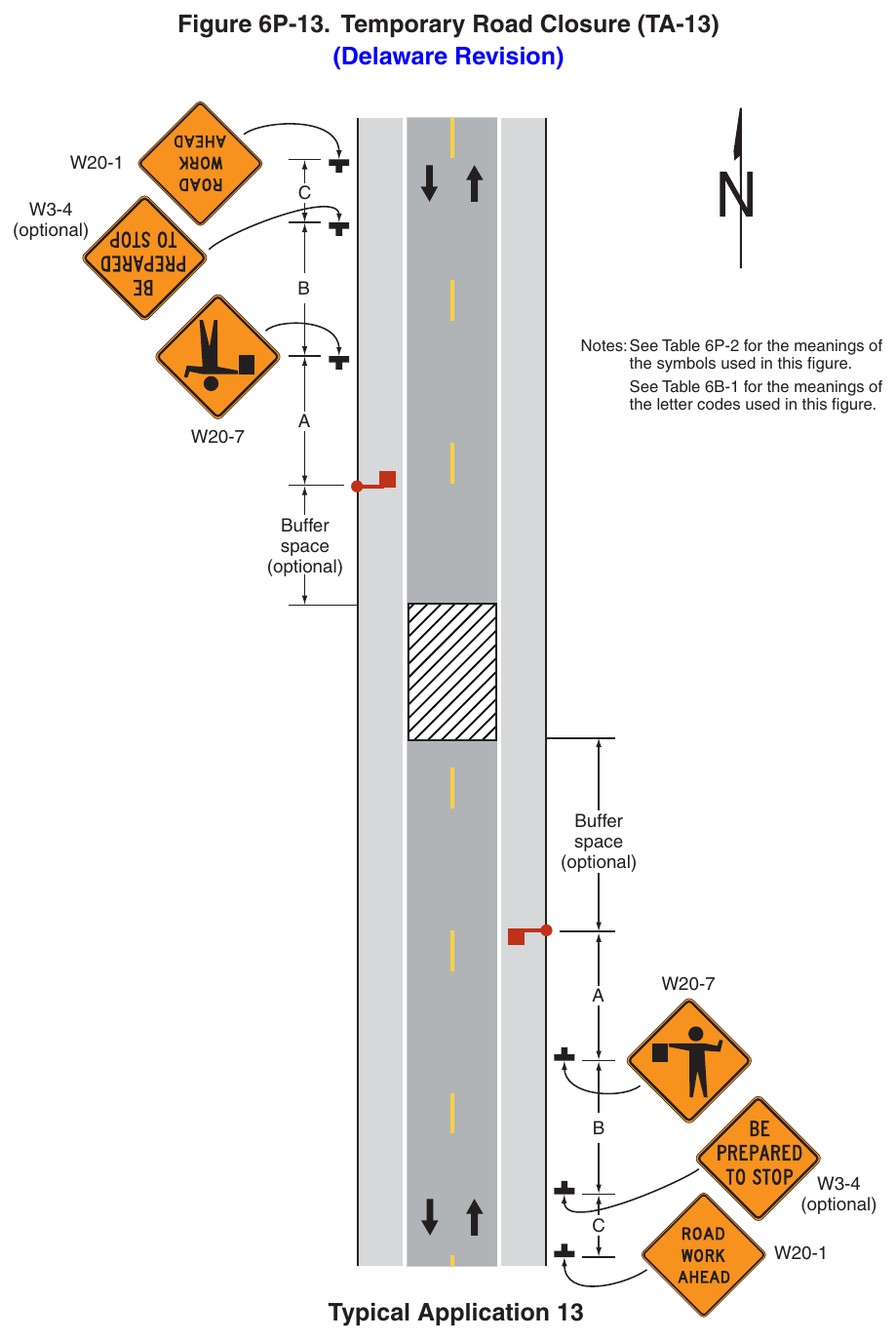
(Delaware Revision) (optional) Notes: See Table 6P-2 for the meanings of the symbols used in this figure. See Table 6B-1 for the meanings of the letter codes used in this figure. Buffer space (optional) Buffer space (optional) (optional) Typical Application 13 Notes for Figure 6P-14—Typical Application 14 (Delaware Revision)
Guidance
- 1. Floodlights should be used to illuminate haul road crossings where existing light is inadequate.
- 2. Where no-passing lines are not already in place, they should be added.
Standard
- 3. The traffic control method selected shall be used in both directions. Flagging Method
- 4. When a road used exclusively as a haul road is not in use, the haul road shall be closed with Type 3 Barricades and the Flagger symbol signs covered.
- 5. The flagger shall follow the procedures provided in Sections 6D.05 and 6D.06.
- 6. At night, flagger stations shall be illuminated, except in emergencies. Signalized Method
- 7. All temporary traffic control signals along state-maintained roadways shall have a signal plan approved by DelDOT Traffic.
- 8. When a road used exclusively as a haul road is not in use, the haul road shall be closed with Type 3 Barricades. The signals shall either:
- a. Flash yellow on the main road and flash red on the haul road or be covered, and the Signal Ahead and STOP HERE ON RED signs shall be covered or hidden from view; or
- b. Display green on the main road and steady red on the haul road, but only if actuated signal operation is used such that green is always displayed to the main road except when a vehicle is detected on the haul road.
- 9. The temporary traffic control signals shall control both the highway and the haul road and shall meet the physical display and operational requirements of conventional traffic control signals as described in Part 4. Traffic control signal timing shall be established by authorized officials.
- 10. Stop lines shall be used on existing highways with temporary traffic control signals.
- 11. Existing conflicting pavements markings between the stop lines shall be removed. After the temporary traffic control signal is removed, the stop lines and other temporary pavement markings shall be removed and the permanent pavement markings restored.
Option
Flagging Method
- 12. Automated Flagger Assistance Devices (see Section 6L.02) may be used in situations where there is only one lane of approaching traffic in the direction to be controlled.
Guidance
Signalized Method
- 13. If actuated signal operation is used (see Item b in Note 7 above) and pedestrian facilities, such as sidewalks, are present in the area of the haul road crossing, then consideration should be given to providing pedestrian actuation capability at the temporary traffic control signal to accommodate any pedestrians who might be depending upon a pedestrian phase to cross the main road.
- 14. If the signalized method is used, the primary signal faces controlling vehicular traffic should be located overhead.
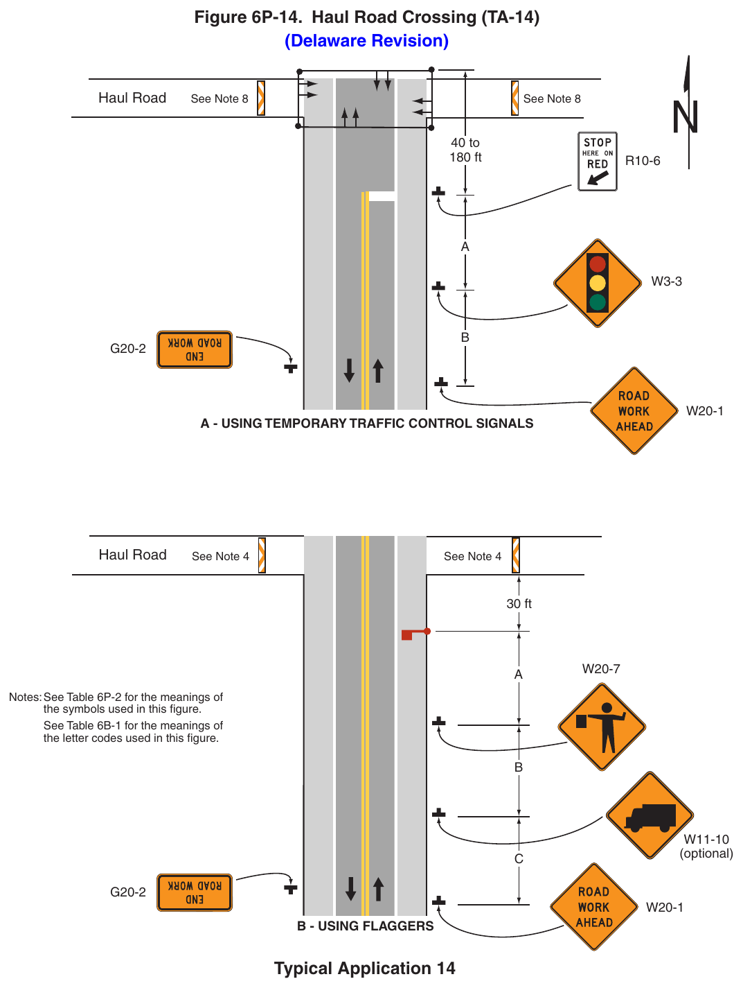
(Delaware Revision) See Note 8 See Note 8 180 ft A - USING TEMPORARY TRAFFIC CONTROL SIGNALS See Note 4 See Note 4 30 ft Notes: See Table 6P-2 for the meanings of the symbols used in this figure. See Table 6B-1 for the meanings of the letter codes used in this figure. (optional) Typical Application 14 Notes for Figure 6P-15—Typical Application 15 Work in the Center of a Road with Low Traffic Volumes (Delaware Revision)
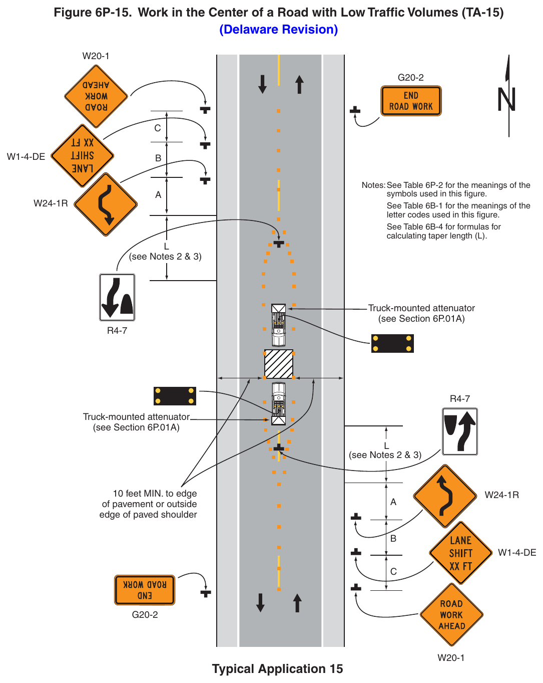
Guidance
from the near edge of the channelizing devices to the edge of the pavement or the outside edge of the
- 2. A shifting taper length of L is preferred on state-maintained roads (see Tables 6B-3 and 6B-4).
- 3. For roadways with a posted speed limit of 35 mph or greater, Double Reverse Curve signs should be used as shown in Figure 6P-15. For roadways with a posted speed limit of 30 mph or less, Double Reverse Turn signs should be used instead of the Double Reverse Curve signs.
- 4. Where drivers emerging from an intersecting roadway will not encounter an advance warning sign prior to the work zone, additional signs should be placed on the intersecting road.
Option
- 5. Positive protection devices may be used per Section 6M.02.
- 6. A lane width of 9 feet may be used for short-term stationary work on low-volume, low-speed roadways when motor vehicle traffic does not include longer and wider heavy commercial vehicles.
- 7. Vehicle hazard warning signals may be used to supplement high-intensity rotating, flashing, oscillating, or strobe lights.
- 8. Shift areas may be illuminated at night, except in emergencies.
Standard
- 9. Vehicle hazard warning signals shall not be used instead of the vehicle’s high-intensity rotating, flashing, oscillating, or strobe lights.
Standard
- 1. The length of the work area shall be limited to a half day’s surveying operation or 1 mile, whichever is less.
- 2. The flaggers shall be in sight of each other or in communication with each other at all times.
Guidance
The lanes on either side of the center work space should have a minimum width of 10 feet as
- 3. Where a side road or major access point, such as a commercial, industrial, or subdivision entrance intersects the work zone, additional flagger(s) should be located in the vicinity of the intersection(s).
- 4. Where drivers emerging from an intersecting roadway will not encounter an advance warning sign prior to the work zone, additional signs should be placed on the intersecting road.
Standard
- 5. For surveying on the center line of a high-volume road, one lane shall be closed using the information illustrated in Figure 6P-10.
Option
- 6. Additional shadow vehicles to warn and reduce the speed of oncoming or opposing vehicular traffic may be used on roadways with a posted speed limit of 45 mph or greater. Law enforcement vehicles may be used for this purpose.
- 7. ROAD WORK AHEAD signs may be used in place of the SURVEY CREW signs.
If the work is along the shoulder, the flagger may be omitted.
- 8. A BE PREPARED TO STOP sign may be added to the sign series.
- 9. Automated Flagger Assistance Devices (see Section 6L.02) may be used in situations where there is only one lane of approaching traffic in the direction to be controlled.
Guidance
- 10. When used, the BE PREPARED TO STOP sign should be located before the Flagger symbol sign.
- 11. For surveying operations along multi-lane roads, the off-roadway surveying operations should be completed first and then the applicable typical application for a short-term or mobile shoulder closure (see Figure 6P-3A or 6P-4A) or lane closure (see Figure 6P-33 or 6P-35) should be used with the exception of the use of SURVEY WORK signs.
- 12. For surveying operations along the centerline of a two-lane road, Figure 6P-13 should be used.
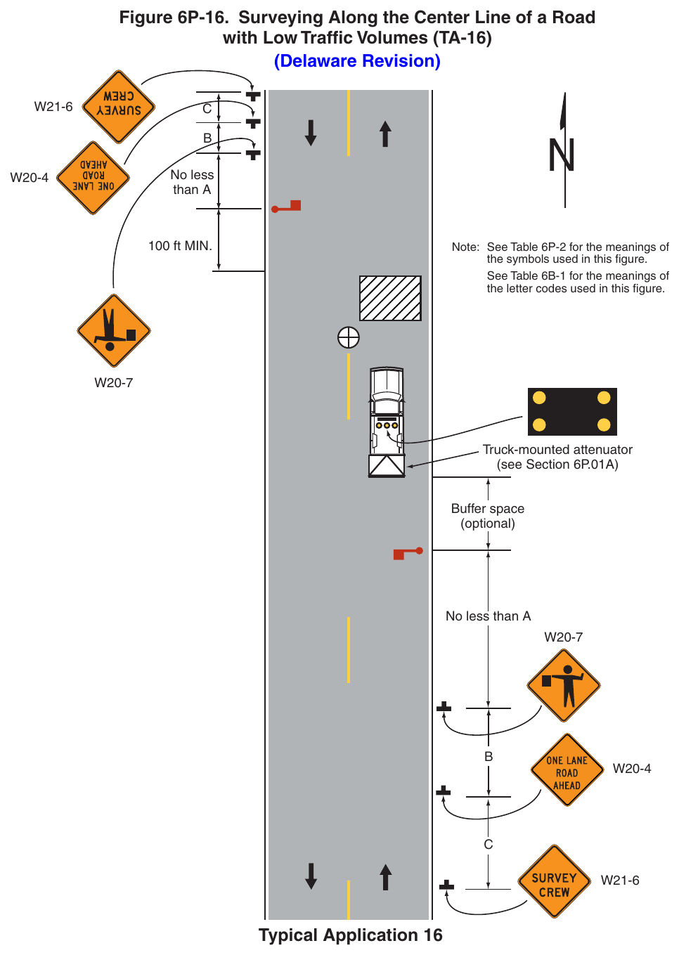
(Delaware Revision) No less 100 ft MIN. Note: See Table 6P-2 for the meanings of the symbols used in this figure. See Table 6B-1 for the meanings of the letter codes used in this figure. Truck-mounted attenuator (see Section 6P.01A) Buffer space (optional) No less than A Typical Application 16 Notes for Figure 6P-17—Typical Application 17 (Delaware Revision)
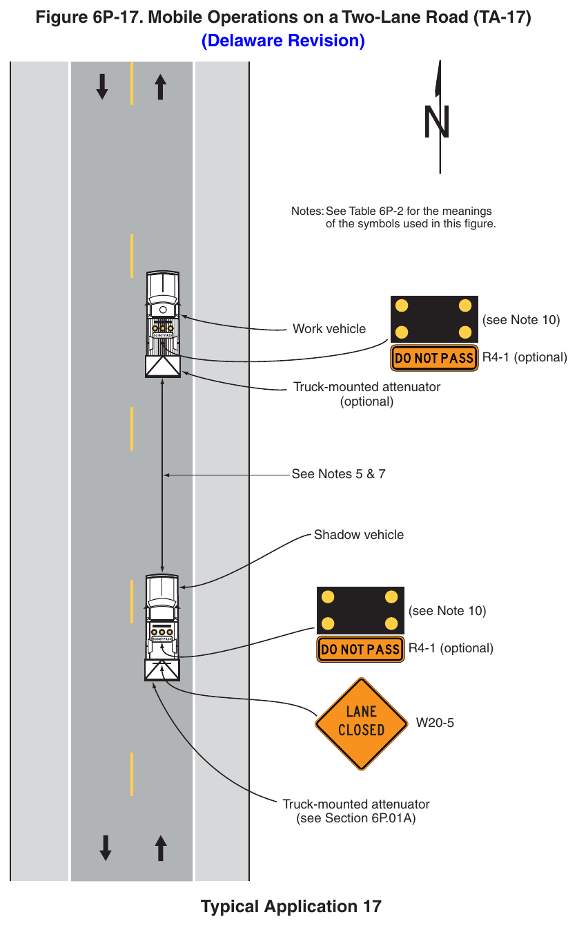
Standard
- 1. Vehicle-mounted signs shall be mounted in a manner such that they are not obscured by equipment or supplies. Sign legends on vehicle-mounted signs shall be covered or turned from view when work is not in progress.
- 2. Shadow and work vehicles shall display high-intensity rotating, flashing, oscillating, or strobe lights.
- 3. If an arrow board is used, it shall be used in the caution mode.
Guidance
- 4. Where practical and when needed, the work and shadow vehicles should pull over periodically to allow vehicular traffic to pass.
- 5. Whenever adequate stopping sight distance exists to the rear, the shadow vehicle should maintain the minimum distance from the work vehicle and proceed at the same speed. The shadow vehicle should slow down in advance of vertical or horizontal curves that restrict sight distance.
Option
- 6. Positive protection devices may be used per Section 6M.02.
- 7. The distance between the work and shadow vehicles may vary according to terrain, paint drying time, and other factors.
- 8. Additional shadow vehicles to warn and reduce the speed of oncoming or opposing vehicular traffic may be used. Law enforcement vehicles may be used for this purpose.
- 9. If the work and shadow vehicles cannot pull over to allow vehicular traffic to pass frequently, a DO NOT PASS sign may be placed on the rear of the vehicle blocking the lane.
- 10. If a work vehicle cannot support the installation of an arrow board, a trailer mounted arrow board may be used.
Support
- 11. Shadow vehicles are used to warn motor vehicle traffic of the operation ahead.
Standard
- 12. Vehicle hazard warning signals shall not be used instead of the vehicle’s high-intensity rotating, flashing, oscillating, or strobe lights.
Standard
- 1. This TTC shall be used only for low-speed facilities having low traffic volumes.
Option
- 2. Where the work space is short, where road users can see the roadway beyond, and where volume is low, vehicular traffic may be self-regulating.
Standard
- 3. Where vehicular traffic cannot effectively self-regulate, one or two flaggers shall be used as illustrated in Figure 6P-10.
Option
- 4. If a work vehicle cannot support the installation of an arrow board, a trailer mounted arrow board may be used.
- 5. A truck-mounted attenuator may be used on the work vehicle and the shadow vehicle.
- 6. Positive protection devices may be used per Section 6M.02.
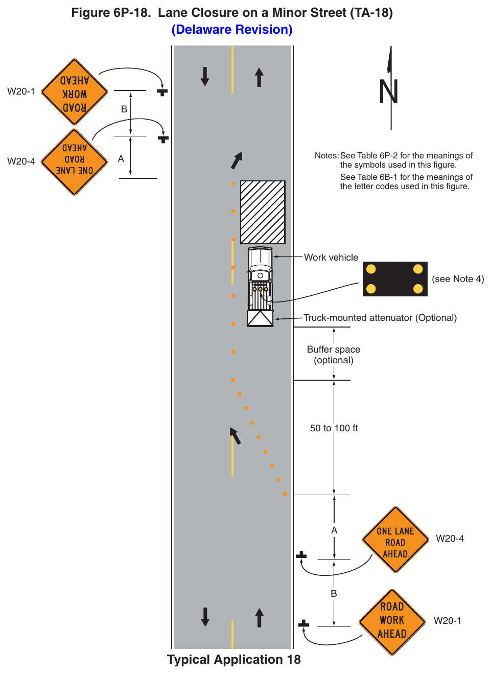
(Delaware Revision) Notes: See Table 6P-2 for the meanings of the symbols used in this figure. See Table 6B-1 for the meanings of the letter codes used in this figure. Work vehicle (see Note 4) Truck-mounted attenuator (Optional) Buffer space (optional) 50 to 100 ft Typical Application 18 Notes for Figure 6P-19—Typical Application 19 (Delaware Revision)
Standard
- 1. The use of this Typical Application on state-maintained roads shall be approved by DelDOT Traffic.
Guidance
- 2. This plan should be used for streets without posted route numbers.
- 3. On multi-lane streets, Detour signs with an Advance Turn Arrow should be used in advance of a turn.
Option
- 4. The STREET CLOSED legend may be used in place of ROAD CLOSED.
- 5. Additional DO NOT ENTER signs may be used at intersections with intervening streets.
- 6. Warning lights may be used on Type 3 Barricades.
- 7. Detour signs may be located on the far side of intersections.
- 8. A Street Name sign may be mounted with the Detour sign. The Street Name sign may be either white on green or black on orange.
Standard
- 9. When used, the Street Name sign shall be placed above the Detour sign.
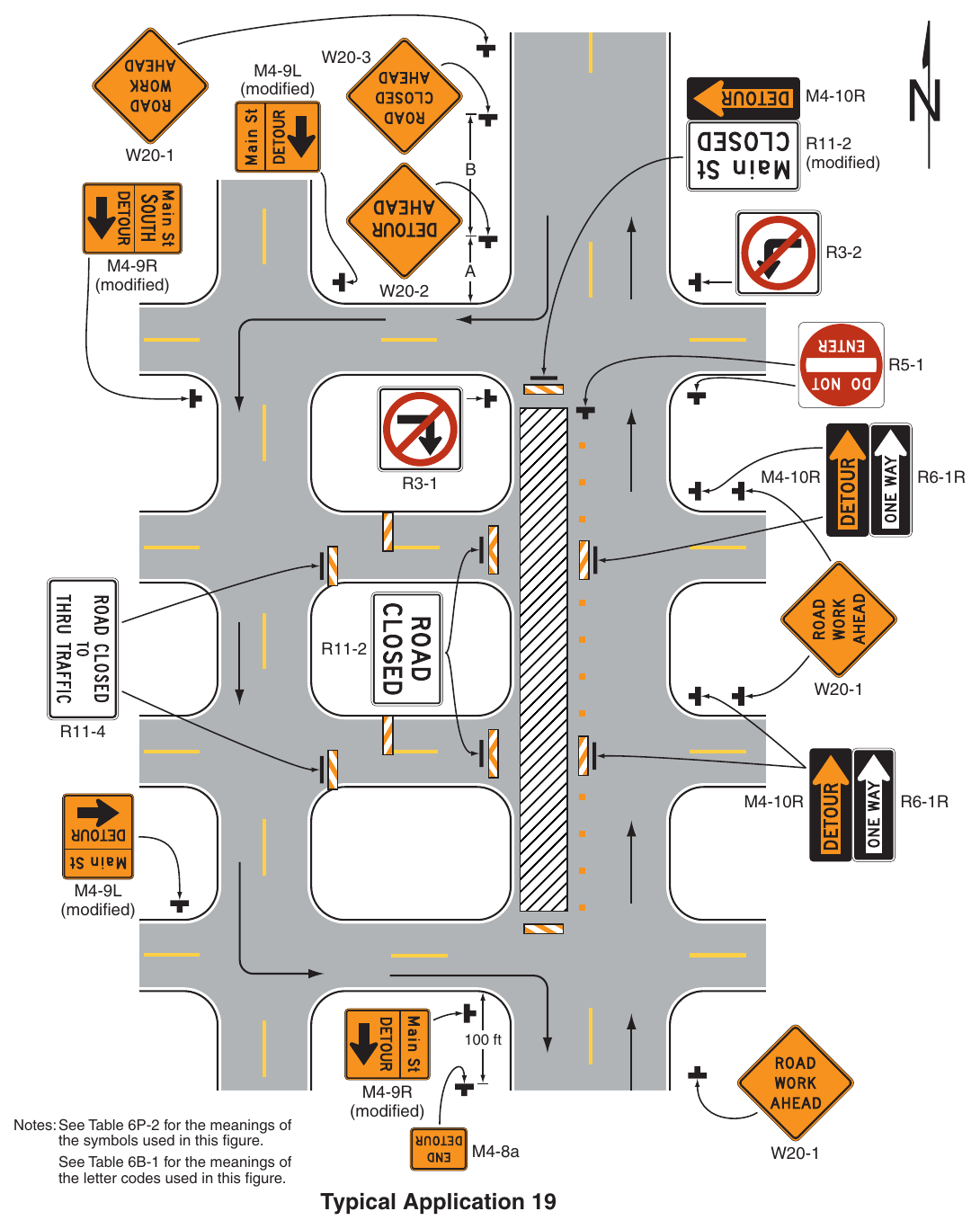
Signs shown: W20-3, M4-9L, M4-10R, R11-2, W20-1, R3-2, M4-9R, W20-2, R5-1, R6-1R, R3-1, R11-4, M4-8a
Notes: See Table 6P-2 for the meanings of the symbols used in this figure. See Table 6B-1 for the meanings of the letter codes used in this figure. (modified) M4-8a Typical Application 19 Notes for Figure 6P-20—Typical Application 20 (Delaware Revision)
Standard
- 1. All detours affecting state-maintained roadways shall have a detour plan approved by DelDOT Traffic.
- 2. Before a road is closed to traffic, all necessary detour signs shall be in place along the corresponding detour route.
Guidance
This plan should be used for streets without posted route numbers.
- 3. Under emergency conditions, personnel should be provided to ensure a safe roadway closure until proper devices are in place.
- 4. Proper devices should be in place within 24 hours of the start of the emergency operation.
- 5. Regulatory traffic control devices should be modified as needed for the duration of the detour.
- 6. On multi-lane streets, Detour signs with an Advance Turn Arrow should be used in advance of a turn.
- 7. On multi-lane, divided highways, detour signs should be mounted on both sides of the directional roadway where adequate lateral clearance is available on the left-hand side of the roadway to accommodate the additional signs.
- 8. For complex or overlapping detours associated with unnumbered routes, as well as approaches to detours that will not encounter an advance warning sign, a Street name sign should be mounted with the Detour sign.
- 9. Route Sign Directional assemblies should be used for long-term detours associated with numbered routes.
- 10. Where drivers emerging from an intersecting roadway will not encounter an advance warning sign prior to the road closure, additional signs should be placed on the intersecting road.
- 11. Detour trailblazer signs should be installed in advance of a decision point (i.e., 200 ft – 300 ft in advance
- 12. The text height for the legend of the custom detour advance notification sign should be as noted in Section 6I.02, paragraph 04B.
Option
- 13. If the road is opened for some distance beyond the intersection and/or there are significant origin/ destination points beyond the intersection, the ROAD CLOSED and DETOUR signs on Type 3 Barricades may be located at the edge of the traveled way.
- 14. Detour signs may be located on the far side of intersections. A Detour sign with an advance arrow may be used in advance of a turn.
- 15. A Street Name sign may be mounted with the Detour sign. The Street Name sign may be either white on green or black on orange.
- 16. Cardinal direction plaques may be used with route signs.
- 17. Additional temporary traffic control devices may be used for detours and road closures on multi-lane, divided highways based on engineering judgment.
- 18. Where there is insufficient space, a single DETOUR AHEAD advance warning sign may be used in place of the DETOUR 1000 FT and the DETOUR 500 FT signs.
- 19. Where there is insufficient space, a single ROAD CLOSED AHEAD advance warning sign may be used in place of the ROAD CLOSED 1000 FT and the ROAD CLOSED 500 FT signs.
Standard
- 20. When used, the Street Name sign shall be placed above the Detour sign.
Support
- 21. Figure 6P-9 contains the information for detouring a numbered highway.
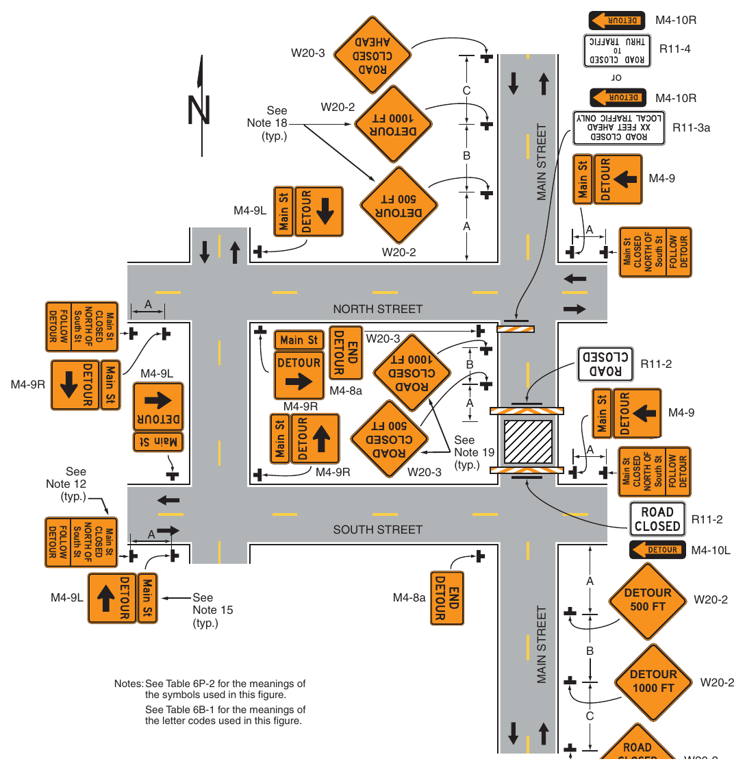
Signs shown: M4-10R, W20-3, R11-4, W20-2, R11-3a, M4-9, M4-9L, R11-2, M4-9R, M4-8a, M4-10L
(Delaware Revision) M4-8a Note 12 (typ.) Note 19 (typ.) Main St South St Note 15 (typ.) M4-8a Main St South St Main St South St R11-3a Main St South St Note 18 (typ.) Notes: See Table 6P-2 for the meanings of the symbols used in this figure. See Table 6B-1 for the meanings of the letter codes used in this figure. Typical Application 20 Notes for Figure 6P-21—Typical Application 21 Lane Closure on the Near Side of an Intersection – Low-Speed (Delaware Revision)
Standard
- 1. The use of this Typical Application on state-maintained roads shall be approved by DelDOT Traffic.
- 2. The merging taper shall direct vehicular traffic into either the right-hand or left-hand lane, but not both.
Guidance
- 3. In this typical application, a left taper should be used so that right-turn movements will not impede through motor vehicle traffic. However, the reverse should be true for left-turn movements.
- 4. For roadways with a posted speed limit of 45 mph or greater, additional warning signs should be used in the advance warning areas (see Figure 6P-33).
- 5. If the work space extends across a crosswalk, the crosswalk should be closed using the information and devices shown in Figure 6P-29.
Option
- 6. Positive protection devices may be used per Section 6M.02.
- 7. Flashing warning lights and/or flags may be used to call attention to the advance warning signs.
- 8. A shadow vehicle with a truck-mounted attenuator may be used.
- 9. A work vehicle with high-intensity rotating, flashing, oscillating, or strobe lights may be used with the high-level warning device.
- 10. Vehicle hazard warning signals may be used to supplement high-intensity rotating, flashing, oscillating, or strobe lights.
Standard
- 11. Vehicle hazard warning signals shall not be used instead of the vehicle’s high-intensity rotating, flashing, oscillating, or strobe lights.
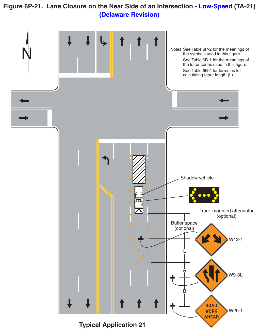
(Delaware Revision) Notes: See Table 6P-2 for the meanings of the symbols used in this figure. See Table 6B-1 for the meanings of the letter codes used in this figure. See Table 6B-4 for formulas for calculating taper length (L). Shadow vehicle Truck-mounted attenuator (optional) Buffer space (optional) Typical Application 21 Notes for Figure 6P-21A—Typical Application 21A Lane Closure on the Near Side of an Intersection on an Undivided, Low-Speed (Delaware Revision)
Standard
- 1. This TTC zone application shall also be used when work is being performed in the left-hand lane. In this case, the LEFT LANE CLOSED sign and the corresponding Lane Ends (or MERGE RIGHT) sign shall be substituted.
- 2. An arrow board shall be used when a lane is closed. When more than one lane is closed, a separate arrow board shall be used for each closed lane.
Guidance
- 3. For roadways with a posted speed limit of 45 mph or greater, additional warning signs should be used in the advance warning area (see Figure 6P-33).
- 4. If the work space extends across a crosswalk, the crosswalk should be closed using the information and devices shown in Figure 6P-29.
- 5. When paved shoulders are closed, channelizing devices should be used to close the shoulder in advance of the merging taper to direct vehicular traffic to remain within the traveled way.
- 6. Where drivers emerging from an intersecting roadway will not encounter an advance warning sign prior to the work zone, additional signs should be placed on the intersecting road.
- 7. Along divided highways, advance warning signs should be omitted from the opposing direction and downstream intersecting roadways.
Option
- 8. Positive protection devices may be used per Section 6M.02.
- 9. Vehicle hazard warning signals may be used to supplement high-intensity rotating, flashing, oscillating, or strobe lights.
- 10. ROAD WORK AHEAD and END ROAD WORK signs may be installed on the intersecting roadways approaching the intersection when work is occurring that impacts vehicular movements to and from the intersecting roadways.
Standard
- 11. Vehicle hazard warning signals shall not be used instead of the vehicle’s high-intensity rotating, flashing, oscillating, or strobe lights.
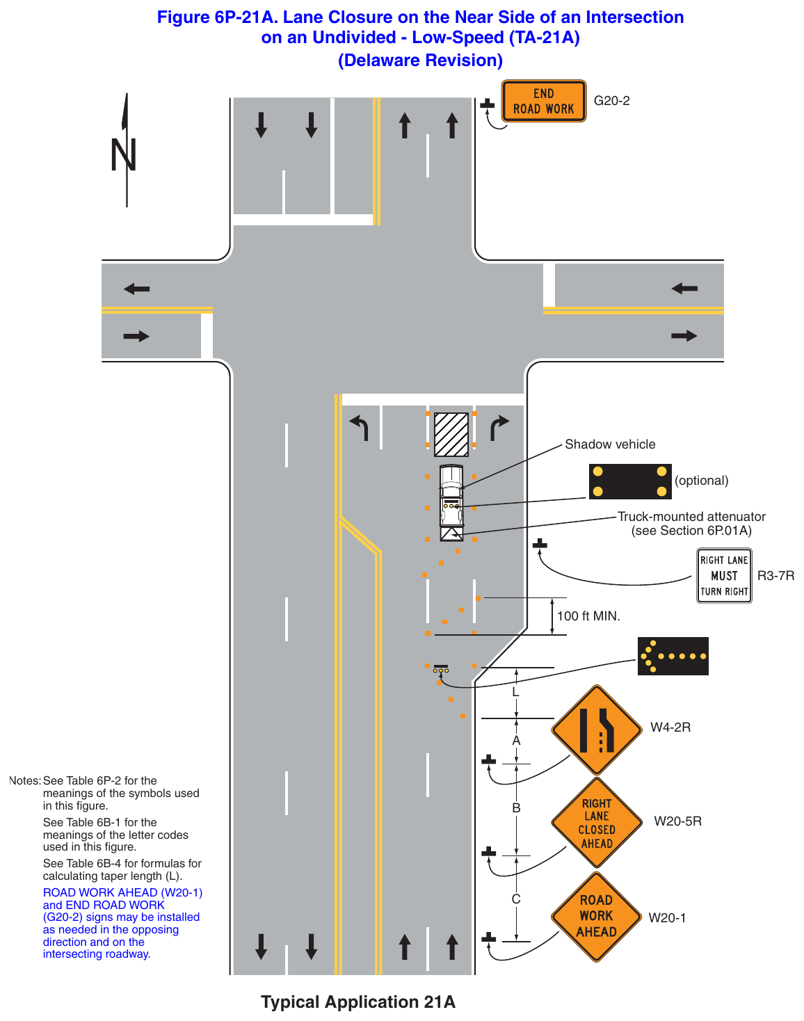
on an Undivided - Low-Speed (TA-21A) (Delaware Revision) Shadow vehicle (optional) Truck-mounted attenuator (see Section 6P.01A) 100 ft MIN. Notes: See Table 6P-2 for the meanings of the symbols used in this figure. See Table 6B-1 for the meanings of the letter codes used in this figure. See Table 6B-4 for formulas for calculating taper length (L). and END ROAD WORK (G20-2) signs may be installed as needed in the opposing intersecting roadway. Typical Application 21A Notes for Figure 6P-21B—Typical Application 21B Turn Lane Closure on the Near Side of an Intersection on an Undivided, Low-Speed (Delaware Revision)
Standard
- 1. This TTC zone application also shall be used when work is being performed in the left-hand turn lane. In this case, the LEFT TURN LANE CLOSED sign shall be substituted.
- 2. An arrow board shall be used when a turn lane is closed. When more than one turn lane is closed, a separate arrow board shall be used for each closed turn lane.
- 3. When paved shoulders are closed, channelizing devices shall be used to close the shoulder in advance to delineate the beginning of the work space and direct vehicular traffic to remain within
Guidance
- 4. If the work space extends across a crosswalk, the crosswalk should be closed using the information and devices shown in Figure 6P-29.
- 5. Where drivers emerging from an intersecting roadway will not encounter an advance warning sign prior to the work zone, additional signs should be placed on the intersecting road.
- 6. Along divided highways, advance warning signs should be omitted from the opposing direction and downstream intersecting roadways.
- 7. For roadways with a posted speed limit of 45 mph or greater, additional warning signs should be used in the advance warning areas (see Figure 6P-33).
Option
- 8. Positive protection devices may be used per Section 6M.02.
- 9. Vehicle hazard warning signals may be used to supplement high-intensity rotating, flashing, or oscillating, or strobe lights.
- 10. ROAD WORK AHEAD and END ROAD WORK signs may be installed on the intersecting roadways approaching the intersection when work is occurring that impacts vehicular movements to and from the intersecting roadways.
Standard
- 11. Vehicle hazard warning signals shall not be used instead of the vehicle’s high-intensity rotating, flashing, oscillating, or strobe lights.
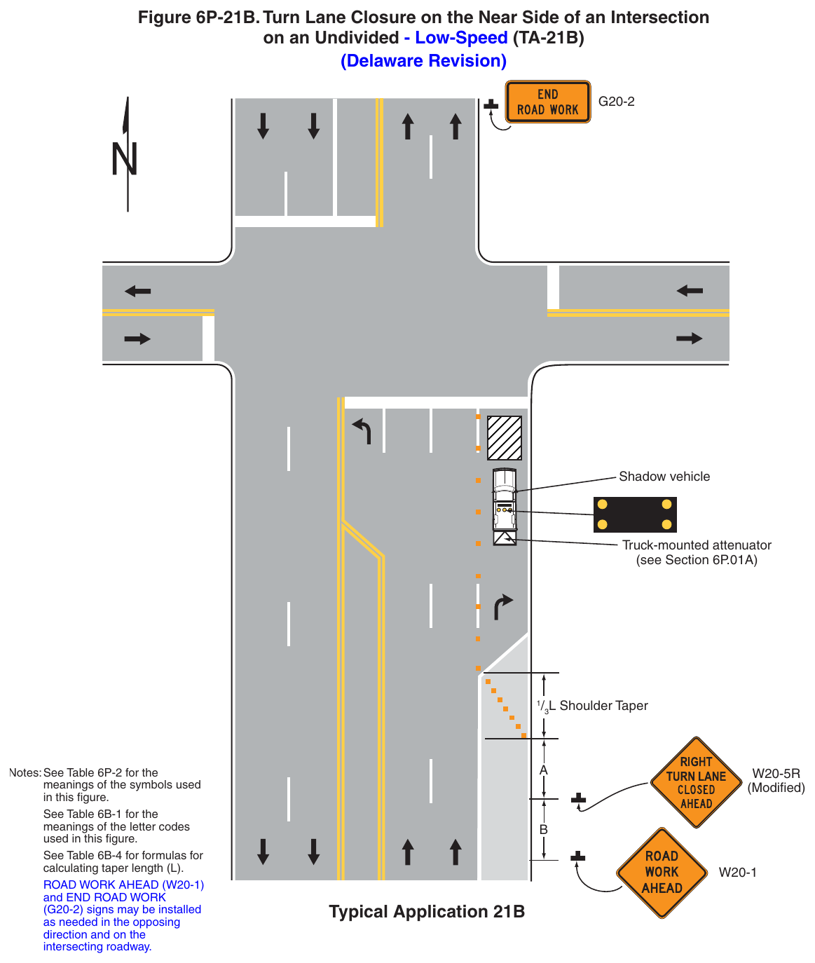
on an Undivided - Low-Speed (TA-21B) (Delaware Revision) Shadow vehicle Truck-mounted attenuator (see Section 6P.01A)
01. Notes: See Table 6P-2 for the meanings of the symbols used in this figure. See Table 6B-1 for the meanings of the letter codes used in this figure. See Table 6B-4 for formulas for calculating taper length (L). and END ROAD WORK (G20-2) signs may be installed as needed in the opposing intersecting roadway. (Modified) Typical Application 21B Notes for Figure 6P-22—Typical Application 22 Right-Hand Lane Closure on the Far Side of an Intersection – Low-Speed (Delaware Revision)
Standard
- 1. The use of this Typical Application on state-maintained roads shall be approved by DelDOT Traffic.
Guidance
- 2. For roadways with a posted speed limit of 45 mph or greater, additional warning signs should be used in the advance warning areas (see Figure 6P-33).
- 3. If the work space extends across a crosswalk, the crosswalk should be closed using the information and devices shown in Figure 6P-29.
Option
- 4. Positive protection devices may be used per Section 6M.02.
- 5. When the normal procedure of closing on the near side of the intersection any lane that is not carried through the intersection results in the closure of a right-hand lane having significant right-turn movements, then the right-hand lane may be restricted to right turns only, requiring through traffic to use the left lane.
- 6. For intersection approaches reduced to a single lane, left-turn movements may be prohibited to maintain capacity for through vehicular traffic.
- 7. Flashing warning lights and/or flags may be used to call attention to the advance warning signs.
- 8. Where the turning radius is large, it may be possible to create a right-turn island using channelizing devices or pavement markings.
- 9. If dimension “A” is not available to create a temporary right-turn lane, continuous channelizers may be installed from the end of the taper to the intersection and, as a result, the RIGHT LANE MUST TURN RIGHT signs would not be installed.
Support
- 10. By first closing off the right-hand lane and then reopening it as a turn bay, the capacity of the through lane is preserved by separating the right-turning vehicles from the through vehicles.
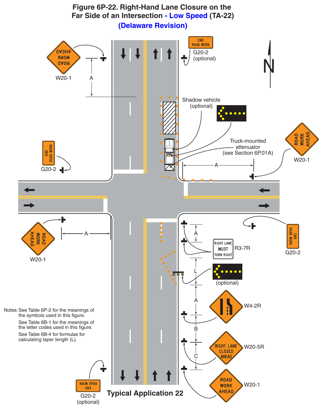
Far Side of an Intersection - Low Speed (TA-22) (Delaware Revision) (optional) Shadow vehicle (optional) Truck-mounted attenuator (see Section 6P.01A) (optional) Notes: See Table 6P-2 for the meanings of the symbols used in this figure. See Table 6B-1 for the meanings of the letter codes used in this figure. See Table 6B-4 for formulas for calculating taper length (L). (optional) Typical Application 22 Notes for Figure 6P-22A—Typical Application 22A Right-Hand Lane Closure on the Far Side of an Intersection on an Undivided, Low-Speed (Delaware Revision)
Standard
- 1. An arrow board shall be used when a lane is closed. When more than one lane is closed, a separate arrow board shall be used for each closed lane.
- 2. Vehicle hazard warning signals shall not be used instead of the vehicle’s high-intensity rotating, flashing, oscillating, or strobe lights.
Guidance
- 3. For roadways with a posted speed limit of 45 mph or greater, additional warning signs should be used in the advance warning area (see Figure 6P-33).
- 4. If the work space extends across a crosswalk, the crosswalk should be closed using the information and devices shown in Figure 6P-29.
- 5. When paved shoulders are closed, channelizing devices should be used to close the shoulder in advance of the merging taper to direct vehicular traffic to remain within the traveled way.
- 6. Where drivers emerging from an intersecting roadway will not encounter an advance warning sign prior to the work zone, additional signs should be placed on the intersecting road.
- 7. Along divided highways, advance warning signs should be omitted from the opposing direction.
Option
- 8. Positive protection devices may be used per Section 6M.02.
- 9. Vehicle hazard warning signals may be used to supplement high-intensity rotating, flashing, oscillating, or strobe lights.
Support
- 10. The normal procedure is to close on the near side of the intersection any lane that is not carried through
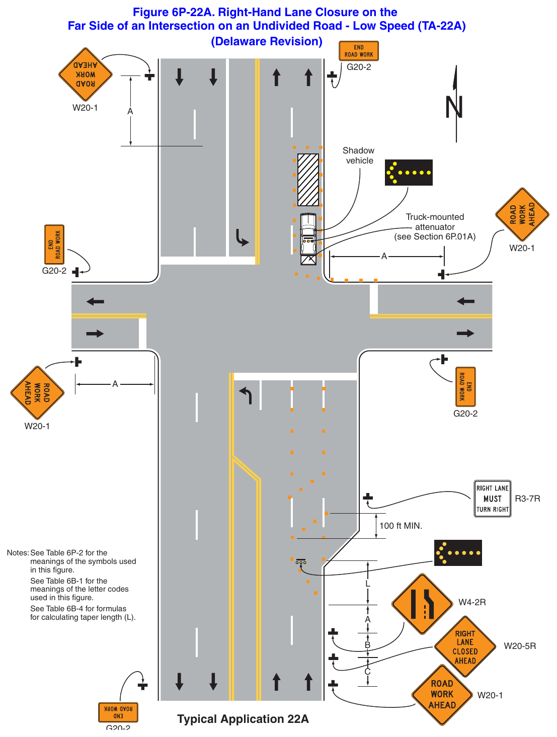
Far Side of an Intersection on an Undivided Road - Low Speed (TA-22A) (Delaware Revision) Shadow vehicle Truck-mounted attenuator (see Section 6P.01A) 100 ft MIN. Notes: See Table 6P-2 for the meanings of the symbols used in this figure. See Table 6B-1 for the meanings of the letter codes used in this figure. See Table 6B-4 for formulas for calculating taper length (L). Typical Application 22A Notes for Figure 6P-23—Typical Application 23 Left-Hand Lane Closure on the Far Side of an Intersection (Delaware Revision)
Standard
- 1. 1. The use of this Typical Application on state-maintained roads shall be approved by DelDOT Traffic.
Guidance
- 2. For roadways with a posted speed limit of 45 mph or greater, ,additional warning signs should be used in the advance warning area (see Figure 6P-33).
- 3. If the work space extends across a crosswalk, the crosswalk should be closed using the information and devices shown in Figure 6P-29.
Option
- 4. Positive protection devices may be used per Section 6M.02.
- 5. Flashing warning lights and/or flags may be used to call attention to the advance warning signs.
- 6. When the normal procedure of closing on the near side of the intersection any lane that is not carried through the intersection results in the closure of a left-hand lane having significant left-turn movements, then the left-hand lane may be reopened as a turn bay for left turns only, as shown.
Support
- 7. By first closing off the left-hand lane and then reopening it as a turn bay, the left-turn bay allows storage of turning vehicles so that the movement of through traffic is not impeded. A left-turn bay that is long enough to accommodate all turning vehicles during a traffic signal cycle will provide the maximum benefit for through traffic. Also, an island is created with channelizing devices that allows the LEFT LANE MUST TURN LEFT sign to be repeated on the left adjacent to the lane that it controls.
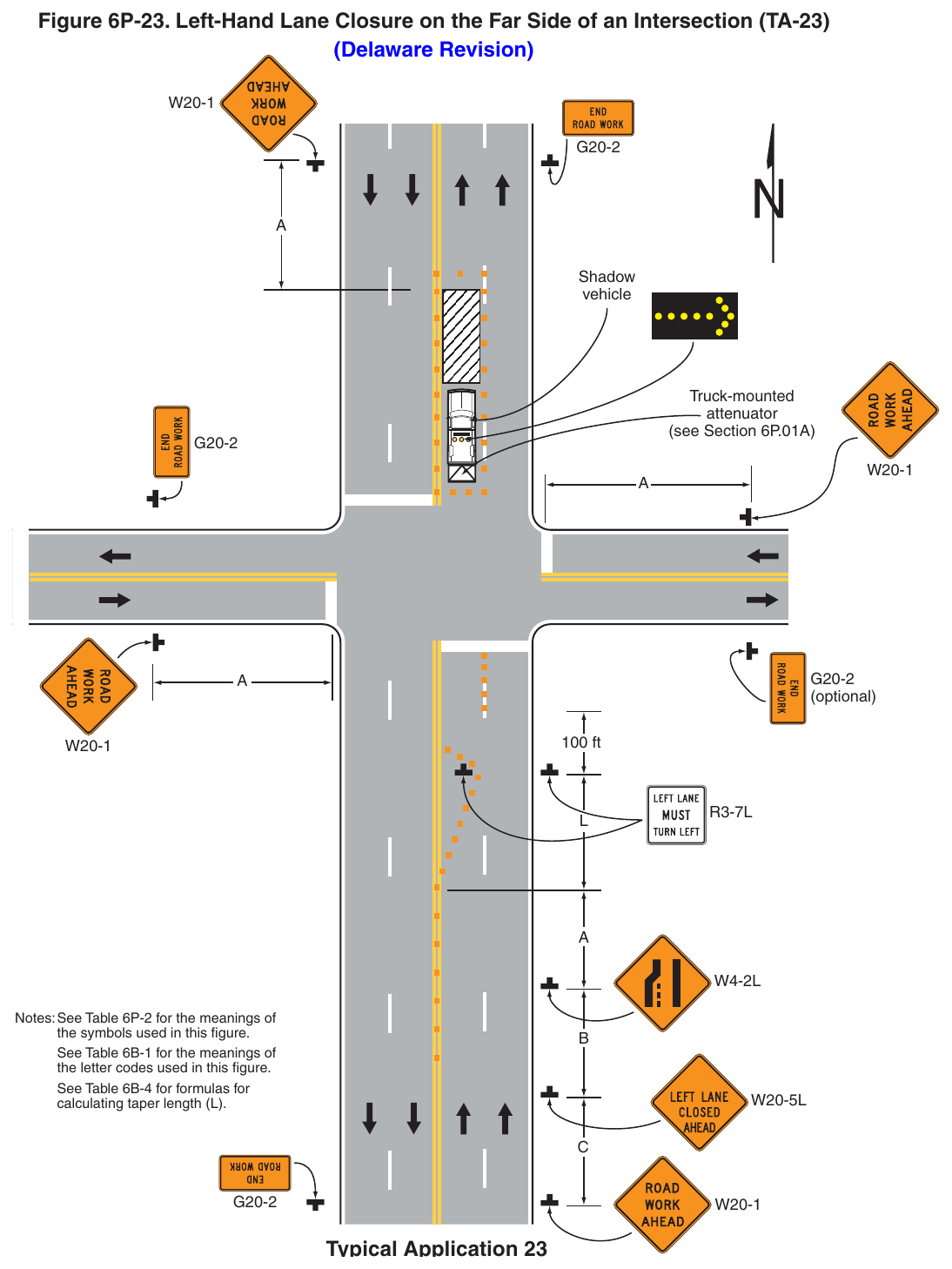
(Delaware Revision) Shadow vehicle Truck-mounted attenuator (see Section 6P.01A) (optional) 100 ft Notes: See Table 6P-2 for the meanings of the symbols used in this figure. See Table 6B-1 for the meanings of the letter codes used in this figure. See Table 6B-4 for formulas for calculating taper length (L). Typical Application 23 Notes for Figure 6P-23A—Typical Application 23A Left-Hand Lane Closure on the Far Side of an Intersection on an Undivided, Low-Speed (Delaware Revision)
Standard
- 1. An arrow board shall be used when a lane is closed. When more than one lane is closed, a separate arrow board shall be used for each closed lane.
- 2. Vehicle hazard warning signals shall not be used instead of the vehicle’s high-intensity rotating, flashing, oscillating, or strobe lights.
Guidance
- 3. For roadways with a posted speed limit of 45 mph or greater, additional warning signs should be used in the advance warning area (see Figure 6P-33).
- 4. If the work space extends across a crosswalk, the crosswalk should be closed using the information and devices shown in Figure 6P-29.
- 5. When paved shoulders are closed, channelizing devices should be used to close the shoulder in advance of the merging taper to direct vehicular traffic to remain within the traveled way.
- 6. Where drivers emerging from an intersecting roadway will not encounter an advance warning sign prior to the work zone, additional signs should be placed on the intersecting road.
- 7. Along divided highways, advance warning signs should be omitted from the opposing direction.
Option
- 8. Positive protection devices may be used per Section 6M.02.
- 9. Vehicle hazard warning signals may be used to supplement high-intensity rotating, flashing, oscillating, or strobe lights.
- 10. Truck-mounted attenuators may be used for all operations along roadways with a posted speed limit of 40
Support
- 11. The normal procedure is to close on the near side of the intersection any lane that is not carried through
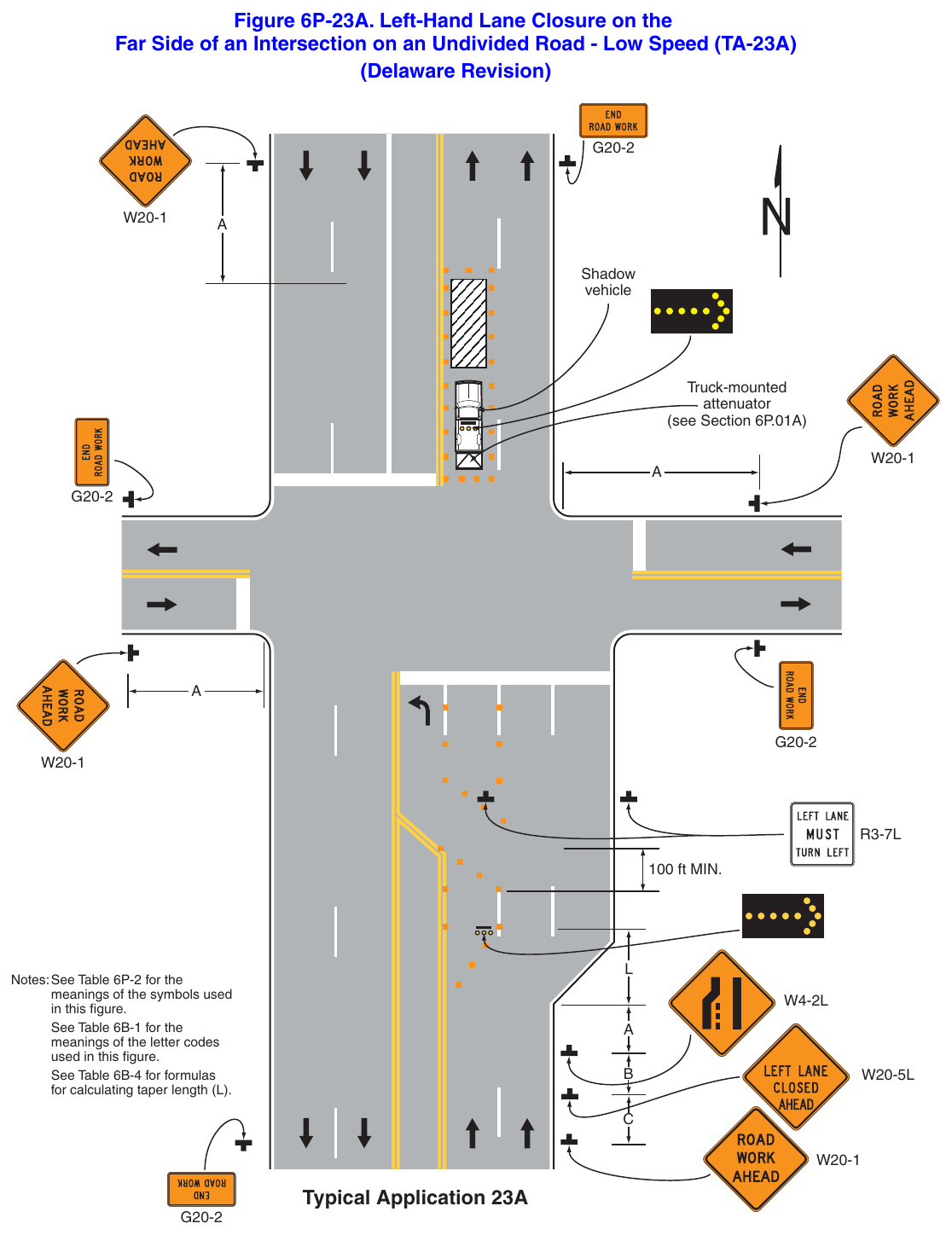
Far Side of an Intersection on an Undivided Road - Low Speed (TA-23A) (Delaware Revision) Shadow vehicle Truck-mounted attenuator (see Section 6P.01A) 100 ft MIN. Notes: See Table 6P-2 for the meanings of the symbols used in this figure. See Table 6B-1 for the meanings of the letter codes used in this figure. See Table 6B-4 for formulas for calculating taper length (L). Typical Application 23A Notes for Figure 6P-24—Typical Application 24 Half Road Closure on the Far Side of an Intersection (Delaware Revision)
Standard
- 1. The use of this Typical Application on state-maintained roads shall be approved by DelDOT Traffic.
Guidance
- 2. If the work space extends across a crosswalk, the crosswalk should be closed using the information and devices shown in Figure 6P-29.
- 3. When turn prohibitions are implemented, two turn prohibition signs should be used, one on the near side and, space permitting, one on the far side of the intersection.
Option
- 4. Positive protection devices may be used per Section 6M.02.
- 5. A buffer space may be used between opposing directions of vehicular traffic as shown in this application.
- 6. When the normal procedure of closing on the near side of the intersection any lane that is not carried through the intersection results in the closure of a right-hand lane having significant right-turn movements, then the right-hand lane may be restricted to right turns only, requiring through traffic to use the left lane.
- 7. Where the turning radius is large, a right-turn island using channelizing devices or pavement markings may be used.
- 8. If there is insufficient space to place the back-to-back Keep Right sign and No Left Turn symbol signs at the end of the row of channelizing devices separating opposing vehicular traffic flows, the No Left Turn symbol sign may be placed on the right and the Keep Right sign may be omitted.
- 9. For intersection approaches reduced to a single lane, left-turn movements may be prohibited to maintain capacity for through vehicular traffic.
- 10. Flashing warning lights and/or flags may be used to call attention to advance warning signs.
- 11. Temporary pavement markings may be used to delineate the travel path through the intersection.
- 12. If dimension “A” is not available to create a temporary right turn lane, continuous channelizers may be installed from the end of the taper to the intersection and, as a result, the RIGHT LANE MUST TURN RIGHT signs would not be installed.
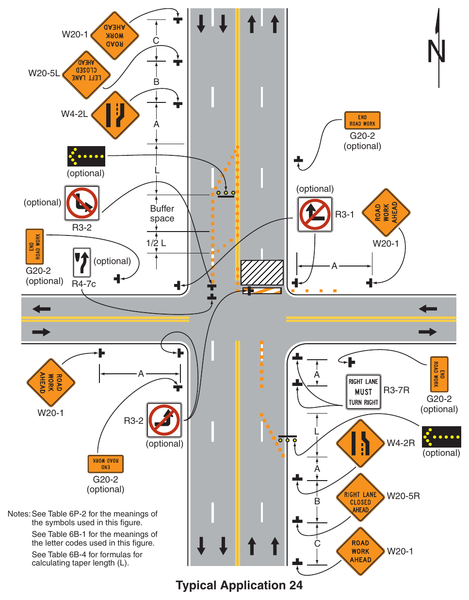
Signs shown: W20-1, W20-5L, W4-2L, G20-2, R3-1, R3-2, R4-7c, R3-7R, W4-2R, W20-5R
(optional) R4-7c (optional) (optional) (optional) (optional) Notes: See Table 6P-2 for the meanings of the symbols used in this figure. See Table 6B-1 for the meanings of the letter codes used in this figure. See Table 6B-4 for formulas for calculating taper length (L). Typical Application 24 Notes for Figure 6P-25—Typical Application 25 (Delaware Revision)
Standard
- 1. The use of this Typical Application on state-maintained roads shall be approved by DelDOT Traffic.
Guidance
- 2. If the work space extends across a crosswalk, the crosswalk should be closed using the information and devices shown in Figure 6P-29.
Support
- 3. The normal procedure is to close on the near side of the intersection any lane that is not carried through the intersection, as shown.
Option
- 4. Positive protection devices may be used per Section 6M.02.
- 5. If the left-turn movement that normally uses the closed turn bay is small and/or the gaps in opposing vehicular traffic are frequent, left turns may be permitted on that approach.
- 6. Flashing warning lights and/or flags may be used to call attention to the advance warning signs.
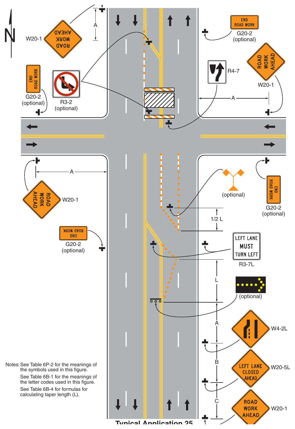
Notes: See Table 6P-2 for the meanings of the symbols used in this figure. See Table 6B-1 for the meanings of the letter codes used in this figure. See Table 6B-4 for formulas for calculating taper length (L). Notes for Figure 6P-26—Typical Application 26 Closure in the Center of an Intersection (Delaware Revision)
Standard
- 1. The use of this Typical Application on state-maintained roads shall be approved by DelDOT Traffic.
Guidance
- 2. All lanes should be a minimum of 10 feet in width as measured to the near face of the channelizing devices.
Option
- 3. A high-level warning device may be placed in the work space, if there is sufficient room.
- 4. For short-term use on low-volume, low-speed roadways with vehicular traffic that does not include longer and wider heavy commercial vehicles, a minimum lane width of 9 feet may be used.
- 5. Flashing warning lights and/or flags may be used to call attention to advance warning signs.
- 6. Left turns may be prohibited as required by geometric conditions, such as where the streets are so narrow that it might be physically impossible to turn left, especially for large vehicles.
- 7. For short-duration work operations, the channelizing devices may be eliminated if a vehicle displaying high-intensity rotating, flashing, oscillating, or strobe lights is positioned in the work space.
- 8. Vehicle hazard warning signals may be used to supplement high-intensity rotating, flashing, oscillating, or strobe lights.
Standard
- 9. Vehicle hazard warning signals shall not be used instead of the vehicle’s high-intensity rotating, flashing, oscillating, or strobe lights.
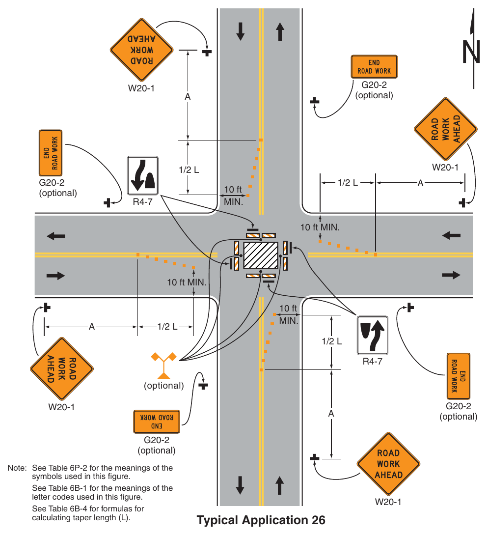
10 ft MIN. 10 ft MIN. 10 ft (optional) (optional) (optional) Note: See Table 6P-2 for the meanings of the symbols used in this figure. See Table 6B-1 for the meanings of the letter codes used in this figure. See Table 6B-4 for formulas for calculating taper length (L). Typical Application 26 Notes for Figure 6P-27—Typical Application 27 Closure at the Side or Center of an Intersection of a Two-Lane Roadway – Low-Speed (Delaware Revision)
Guidance
- 1. The situation depicted can be simplified by closing one or more of the intersection approaches. If this cannot be done, and/or when capacity is a problem, through vehicular traffic should be directed to other roads or streets.
- 2. Depending on road user conditions, flagger(s) or uniformed law enforcement officer(s) should be used to direct road users within the intersection.
Standard
- 3. At night, flagger and uniformed law enforcement officer stations shall be illuminated, except in emergencies.
Option
- 4. A BE PREPARED TO STOP sign may be added to the sign series.
Guidance
- 5. When used, the BE PREPARED TO STOP sign should be located before the Flagger symbol sign.
Support
- 6. Turns may be prohibited as required by vehicular traffic conditions, such as where the streets are so narrow that it might be physically impossible to make certain turns, especially for large vehicles.
Option
- 7. Positive protection devices may be used per Section 6M.02.
- 8. Vehicle hazard warning signals may be used to supplement high-intensity rotating, flashing, oscillating, or strobe lights.
Standard
- 9. Vehicle hazard warning signals shall not be used instead of the vehicle’s high-intensity rotating, flashing, oscillating, or strobe lights.
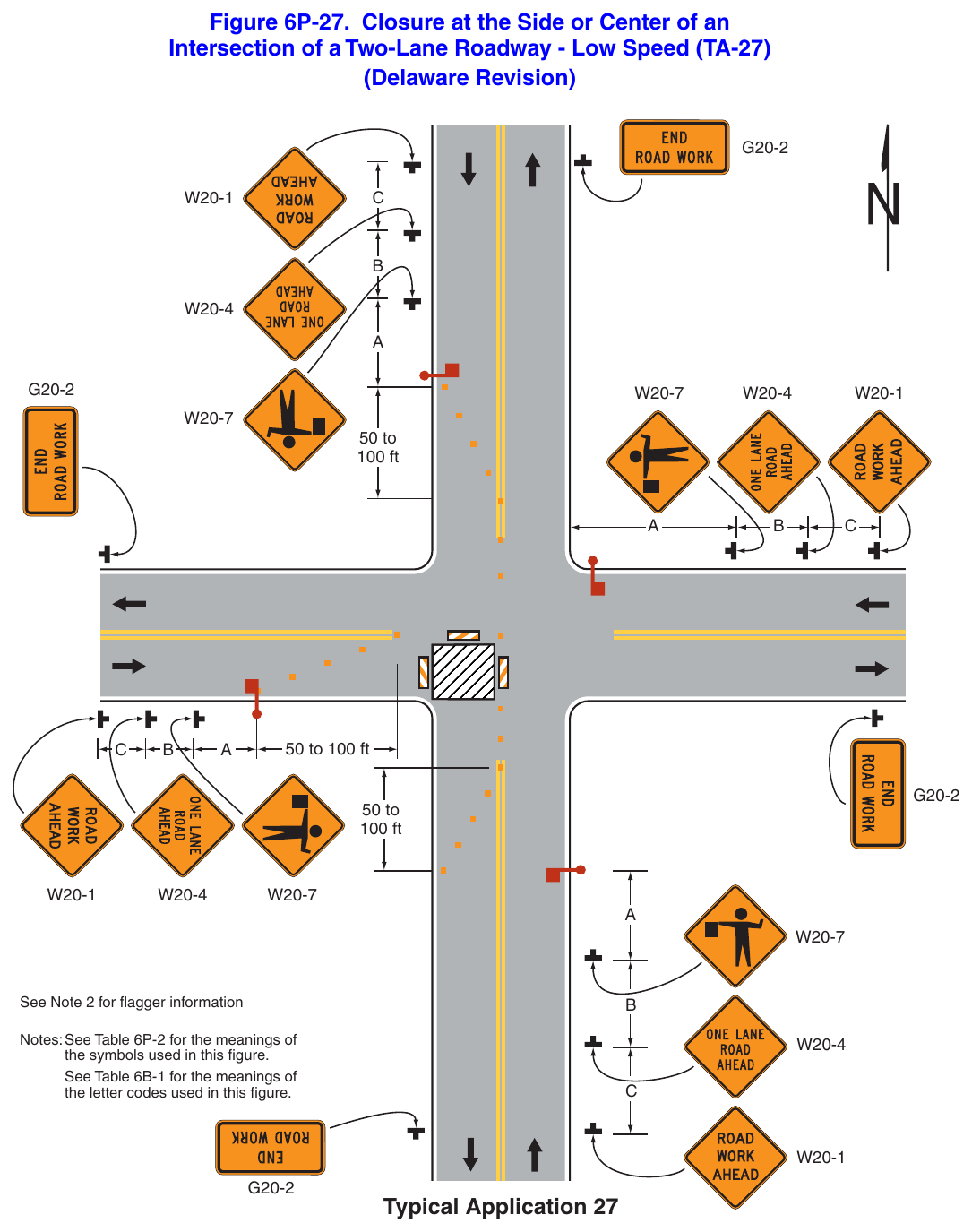
Intersection of a Two-Lane Roadway - Low Speed (TA-27) (Delaware Revision) 50 to 100 ft 50 to 100 ft 50 to 100 ft See Note 2 for flagger information Notes: See Table 6P-2 for the meanings of the symbols used in this figure. See Table 6B-1 for the meanings of the letter codes used in this figure. Typical Application 27 Notes for Figure 6P-28—Typical Application 28 (Delaware Revision)
Standard
- 1. Pedestrian detours along state-maintained roadways shall have a pedestrian detour plan approved by DelDOT Traffic.
- 2. When existing pedestrian facilities are disrupted, closed, or relocated in a TTC zone, the temporary facilities shall be detectable and include accessibility features consistent with the features present in the existing pedestrian facility. A pedestrian channelizing device (see Figure 6K-2) that is detectable by a person with a vision disability traveling with the aid of a long cane shall be placed across the full width of the closed sidewalk.
- 3. When used, temporary ramps shall provide a 12:1 (8.33%) or flatter slope, with a slip-resistant surface. The ramp landing area shall provide a 48-inch x 48-inch minimum area with a 2% or flatter cross-slope.
- 4. When used, Longitudinal Channelizing Devices used for temporary pedestrian routes shall comply with Section 6K.02.
- 5. Temporary traffic barriers, if used, shall comply with the provisions of Section 6M.02.
- 6. SIDEWALK CLOSED CROSS HERE signs shall include audible information devices to provide adequate communication to pedestrians with vision disabilities.
- 7. Audible information devices shall be provided where midblock sidewalk closings and changed crosswalk areas cause inadequate communication to be provided to pedestrians with vision disabilities.
Guidance
- 8. The surface of an alternate pathway should meet the requirements of the U.S. Department of Justice 2010 ADA Standards for Accessible Design, September 15, 2010, 28 CFR 35 and 36, Americans with Disabilities Act of 1990.
- 9. The protective requirements of a TTC situation have priority in determining the need for temporary traffic barriers and their use in this situation should be based on engineering judgment.
Option
- 10. Street lighting may be considered.
- 11. Only the TTC devices related to pedestrians are shown. Other devices, such as lane closure signing or ROAD NARROWS signs, may be used to control vehicular traffic.
- 12. Signs, such as KEEP RIGHT (LEFT), may be placed along a temporary sidewalk to guide or direct pedestrians.
- 13. The width of the alternate pedestrian route may be 48 inches with a passing area of 60 inches every 200 feet.
- 14. If an existing pedestrian route does not have audible pedestrian crossings, audible information devices may be omitted.
- 15. A flagger may be used in lieu of an audible information device during short duration operations.
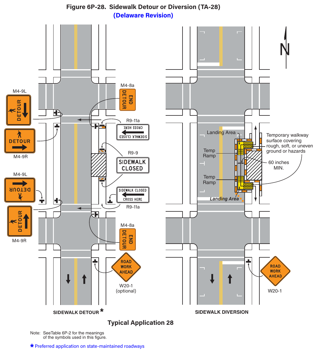
(Delaware Revision) M4-8a R9-11a Landing Area Temp Temporary walkway surface covering rough, soft, or uneven ground or hazards 60 inches Temp Landing Area R9-11a M4-8a (optional) Typical Application 28 Note: SeeTable 6P-2 for the meanings of the symbols used in this figure. Preferred application on state-maintained roadways Notes for Figure 6P-29—Typical Application 29 (Delaware Revision)
Standard
- 1. Pedestrian detours along state-maintained roadways shall have a pedestrian detour plan approved by DelDOT Traffic.
- 2. When crosswalks or other pedestrian facilities are closed or relocated, temporary facilities shall be detectable and shall include accessibility features consistent with the features present in the existing pedestrian facility.
- 3. Temporary midblock crosswalks across uncontrolled approaches are discouraged. If approved by DelDOT Traffic, temporary midblock crosswalks across uncontrolled approaches shall be installed based on the requirements and guidelines in Parts 2 and 3.
- 4. Curb parking shall be prohibited for at least 50 feet in advance of the midblock crosswalk.
- 5. SIDEWALK CLOSED CROSS HERE signs shall include audible information devices to provide adequate communication to pedestrians with vision disabilities.
- 6. Audible information devices shall be provided where midblock sidewalk closings and changed crosswalk areas cause inadequate communication to be provided to pedestrians with vision disabilities.
Guidance
- 7. Pedestrian traffic signal displays controlling closed crosswalks should be covered or deactivated.
Option
- 8. Street lighting may be considered.
- 9. Only the TTC devices related to pedestrians are shown. Other devices, such as lane closure signing or ROAD NARROWS signs, may be used to control vehicular traffic.
Type C Steady-Burn or Type D 360-degree Steady-Burn warning lights may be used on channelizing
- 10. In order to maintain the systematic use of the fluorescent yellow-green background for pedestrian, bicycle, and school warning signs in a jurisdiction, the fluorescent yellow-green background for pedestrian, bicycle, and school warning signs may be used in TTC zones.
- 11. Positive protection devices may be used per Section 6M.02.
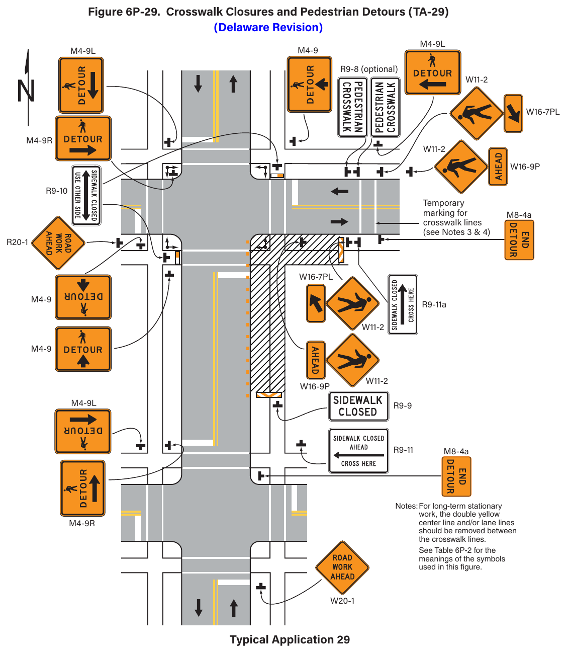
Signs shown: M4-9L, M4-9, R9-8, W11-2, M4-9R, W16-9P, R9-10, M8-4a, R20-1, R9-11a, R9-9, R9-11, W20-1
(Delaware Revision) R9-8 (optional) marking for crosswalk lines (see Notes 3 & 4) M8-4a R9-11a M8-4a Notes: For long-term stationary work, the double yellow center line and/or lane lines should be removed between the crosswalk lines. See Table 6P-2 for the meanings of the symbols used in this figure. Typical Application 29 Notes for Figure 6P-30—Typical Application 30 Interior Lane Closure on a Multi-Lane Street (Delaware Revision)
Guidance
- 1. This information applies to low-speed, low-volume urban streets. Where speed or volume is higher, additional signing such as LEFT LANE CLOSED XX FT should be used between the signs shown.
- 2. Where drivers emerging from an intersecting roadway will not encounter an advance warning sign prior to the work zone, additional signs should be placed on the intersecting road.
Standard
- 3. When only the left lane is closed on undivided roads, channelizing devices shall be placed along the center line as well as along the adjacent lane.
- 4. An arrow board shall be used when a lane is closed. When more than one lane is closed, a separate arrow board shall be used for each closed lane.
- 5. Vehicle hazard warning signals shall not be used instead of the vehicle’s high-intensity rotating, flashing, oscillating, or strobe lights.
Option
- 6. Positive protection devices may be used per Section 6M.02.
- 7. Vehicle hazard warning signals may be used to supplement high-intensity rotating, flashing, oscillating, or strobe lights.
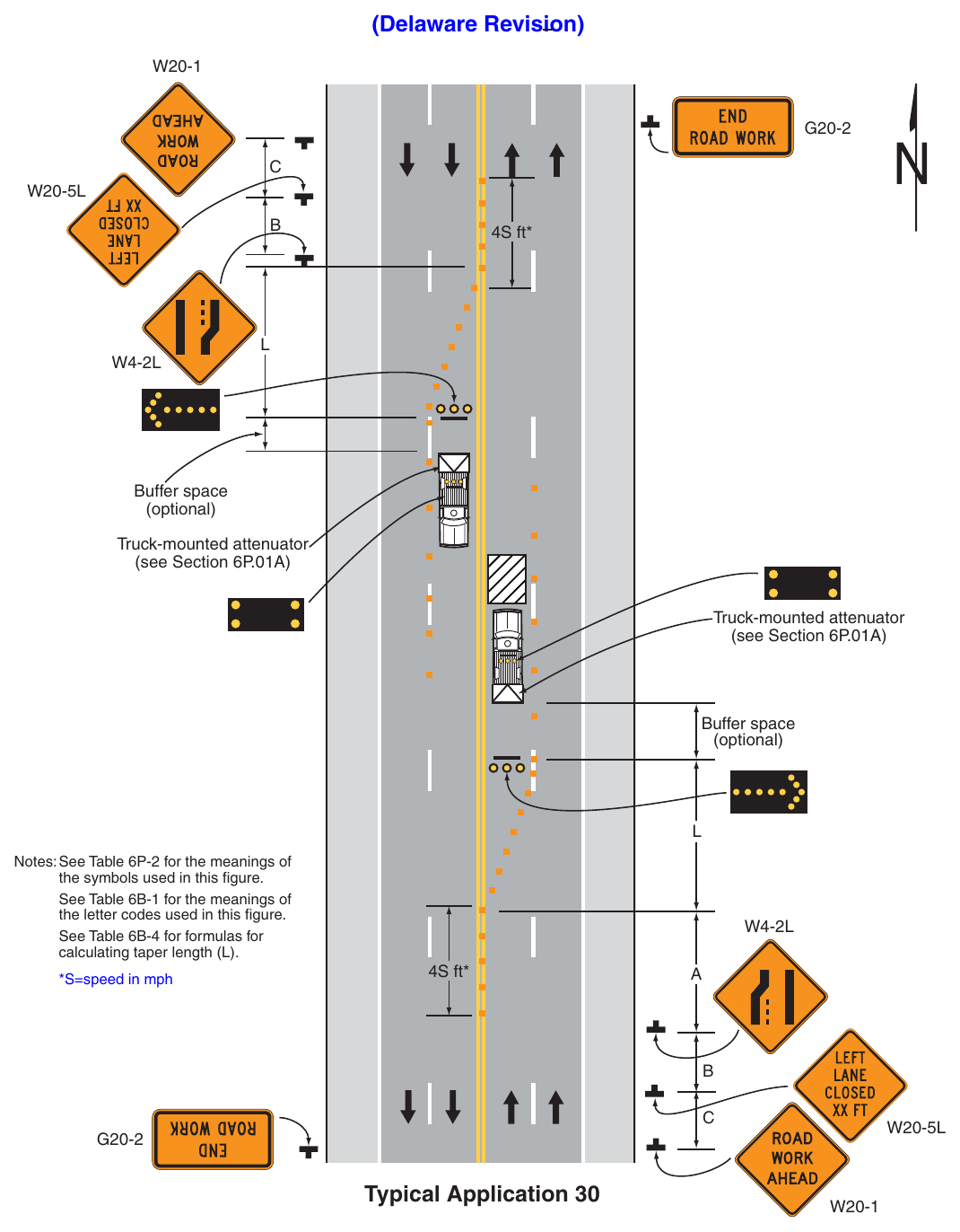
(Delaware Revision) 4S ft Buffer space (optional) Truck-mounted attenuator (see Section 6P.01A) Truck-mounted attenuator (see Section 6P.01A) Buffer space (optional) Notes: See Table 6P-2 for the meanings of the symbols used in this figure. See Table 6B-1 for the meanings of the letter codes used in this figure. See Table 6B-4 for formulas for calculating taper length (L). S=speed in mph 4S ft* Typical Application 30 Notes for Figure 6P-31—Typical Application 31 Lane Closure on a Street with Uneven Directional Volumes (Delaware Revision)
Standard
- 1. The illustrated information shall be used only when the vehicular traffic volume indicates that two lanes of vehicular traffic shall be maintained in the direction of travel for which one lane is closed.
Option
- 2. The procedure may be used during a peak period of vehicular traffic and then changed to provide two lanes in the other direction for the other peak.
Guidance
- 3. For high speeds, a LEFT LANE CLOSED XX FT sign should be added for vehicular traffic approaching the lane closure, as shown in Figure 6P-32.
- 4. Conflicting pavement markings should be removed for long-term projects. For short-term and intermediate-term projects where this is impracticable, the channelizing devices in the area where the pavement markings conflict should be placed at a maximum spacing of ½ S feet where S is the speed in mph. Temporary markings should be installed where needed.
- 5. If the lane shift has curves with recommended speeds of 30 mph or less, Reverse Turn signs should be used.
- 6. A shifting taper length of L is preferred on state-maintained roads (see Tables 6B-3 and 6B-4).
- 7. Where the shifted section is long, a Reverse Curve sign should be used to show the initial shift and a second sign should be used to show the return to the normal alignment.
- 8. If the tangent distance along the temporary diversion is less than 600 feet, the Double Reverse Curve sign should be used at the location of the first Two Lane Reverse Curve sign. The second Two Lane Reverse Curve sign should be omitted.
- 9. Where drivers emerging from an intersecting roadway will not encounter an advance warning sign prior to the work zone, additional signs should be placed on the intersecting road.
Standard
- 10. Except as provided in Note 16 below, the number of lanes illustrated on the Reverse Curve (Turn) or Double Reverse Curve (Turn) signs shall be the same as the number of through lanes available to road users, and the direction of the reverse curves shall be appropriately illustrated.
- 11. An arrow board shall be used when a lane is closed. When more than one lane is closed, a separate arrow board shall be used for each closed lane.
- 12. Vehicle hazard warning signals shall not be used instead of the vehicle’s high-intensity rotating, flashing, oscillating, or strobe lights.
Option
- 13. Positive protection devices may be used per Section 6M.02.
- 14. A longitudinal buffer space may be used in the activity area to separate opposing vehicular traffic.
- 15. Where two or more lanes are being shifted, a Reverse Curve (or Reverse Turn) sign with an ALL LANES plaque (see Figure 6H-1) may be used instead of a sign that illustrates the number of lanes.
- 16. Where more than three lanes are being shifted, the Reverse Curve (or Turn) sign may be rectangular.
- 17. A work vehicle or a shadow vehicle may be equipped with a truck-mounted attenuator.
- 18. Vehicle hazard warning signals may be used to supplement high-intensity rotating, flashing, oscillating, or strobe lights.
- 19. Shift areas may be illuminated at night, except in emergencies.
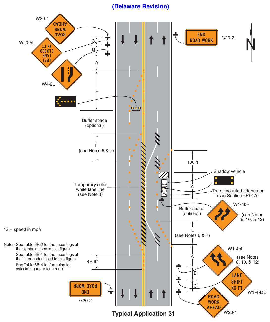
Standard
- 1. Pavement markings no longer applicable shall be removed or obliterated as soon as practical. Except for intermediate-term and short-term situations, temporary markings shall be provided to clearly delineate the temporary travel path. For short-term and intermediate-term situations where it is not feasible to remove and restore pavement markings, channelization shall be made dominant by using a very close device spacing.
- 2. An arrow board shall be used when a lane is closed. When more than one lane is closed, a separate arrow board shall be used for each closed lane.
Guidance
- 3. When paved shoulders are closed, channelizing devices should be used to close the shoulder in advance of the merging taper to direct vehicular traffic to remain within the
- 4. Where channelizing devices are used instead of pavement markings, the maximum spacing should be ½ S feet where S is the speed in mph.
- 5. If the tangent distance along the temporary diversion is less than 600 feet, a Double Reverse Curve sign should be used instead of the first Reverse Curve sign, and the second Reverse Curve sign should be omitted.
- 6. A shifting taper of length L is preferred on state-maintained roads (see Tables 6B-3 and 6B-4).
- 7. If the lane shift has curves with recommended speeds of 30 mph or less, Reverse Turn signs should be used.
- 8. If the tangent distance along the temporary diversion is less than 600 feet, a Double Reverse Curve (Turn) sign should be used instead of the upstream Reverse Curve (Turn) sign and the downstream Reverse Curve (Turn) sign should be omitted.
- 9. Advisory speed plaques should be used only when the advisory speed is less than the posted speed limit.
- 10. Where drivers emerging from an intersecting roadway will not encounter an advance warning sign prior to the work zone, additional signs should be placed on the intersecting road.
Option
- 11. Positive protection devices may be used per Section 6M.02.
- 12. Warning lights may be used to supplement channelizing devices at night.
A truck-mounted attenuator may be used on the work vehicle and/or the shadow vehicle.
- 13. A longitudinal buffer space may be used in the activity area.
- 14. Shift areas may be illuminated at night, except in emergencies.
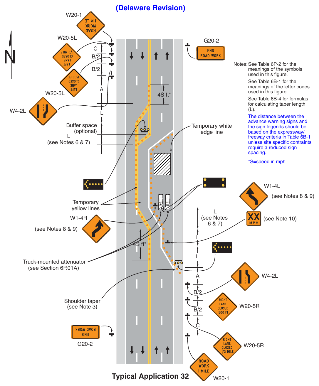
Standard
- 1. This TTC zone application also shall be used when work is being performed in the lane adjacent to the median on a divided highway. In this case, the LEFT LANE CLOSED signs and the corresponding Lane Ends signs shall be substituted.
- 2. When a side road intersects the highway within the TTC zone, additional TTC devices shall be placed as needed.
Guidance
- 3. When paved shoulders are closed, channelizing devices should be used to close the shoulder in advance of the merging taper to direct vehicular traffic to remain within the
- 4. On multi-lane undivided roads and multi-lane, divided highways with narrow medians, the advance warning signs on the left-hand side of the directional roadway should be eliminated
Option
- 5. Positive protection devices may be used per Section 6M.02.
Support
- 6. Where conditions permit, restricting all vehicles, equipment, workers, and their activities to one side of the roadway might be advantageous.
Standard
- 7. An arrow board shall be used when a lane is closed. When more than one lane is closed, a separate arrow board shall be used for each closed lane.
Guidance
- 8. When a grade crossing exists within or upstream of the transition or activity area, see Figure 6P-46.
- 9. When a lane shift is to immediately follow a lane closure, a tangent length of L (preferred) or 1/2L (minimum) should be provided between the end of the merging taper and the beginning of the lane shift taper. Advance warning signage for the lane shift should follow Figure 6P-11B.
- 10. Where drivers emerging from an intersecting roadway will not encounter an advance warning sign prior to the work zone, additional signs should be placed on the intersecting road.
- 11. For roadways with posted speed limits of 40 mph or less, the typical application shown in Figure 6P-37 should be modified as follows:
- a. Sign spacing should be based on Table 6B-1 for urban high-speed or low-speed conditions, dependent upon the posted speed limit,
- b. Taper lengths should be based on the posted speed limit,
- c. The tangent length between merging tapers should be reduced to L, and
- d. Instead of displaying distances on the advance warning signs, use the legend AHEAD
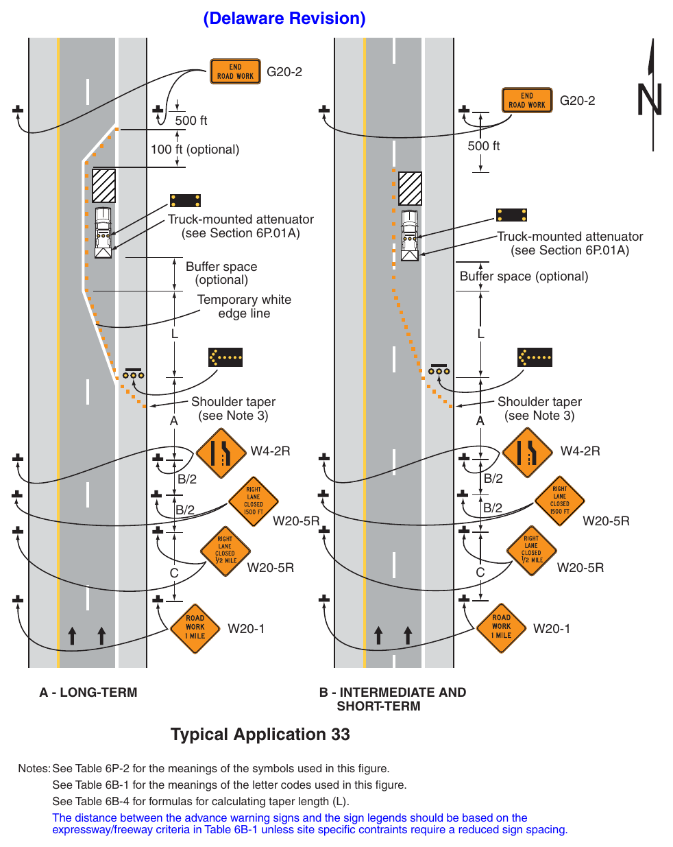
Standard
- 1. This TTC zone application also shall be used when work is being performed in the lane adjacent to the median on a divided highway. In this case, the LEFT LANE CLOSED signs and the corresponding Lane Ends signs shall be substituted.
Guidance
- 2. When paved shoulders are closed, channelizing devices should be used to close the shoulder in advance of the merging taper to direct vehicular traffic to remain within the traveled way.
- 3. On multi-lane, undivided roads and multi-lane, divided highways with narrow medians, the advance warning signs on the left-hand side of the directional roadway should be eliminated.
- 4. For long-term lane closures on facilities with permanent edge lines, a temporary edge line should be installed from the upstream end of the merging taper to the downstream end of the downstream taper, and conflicting pavement markings should be removed.
- 5. The use of a barrier should be based on engineering judgment.
Standard
- 6. Temporary traffic barriers, if used, shall comply with the provisions of Section 6M.02.
- 7. If used, the use of temporary traffic barrier affecting state-maintained roadways shall be based on a design approved by DelDOT Traffic. The design shall include length of need calculations, taper layouts, determination of deflection needs, typical sections, and provisions of runout areas.
- 8. The barrier shall not be placed along the merging taper. The lane shall first be closed using channelizing devices and pavement markings.
- 9. An arrow board shall be used when a lane is closed. When more than one lane is closed, a separate arrow board shall be used for each closed lane.
Option
- 10. The barrier shown in this typical application is an example of one method that may be used to close a lane for a long-term project. If the work activity permits, a movable barrier may be used and relocated to the shoulder during non-work periods or peak-period vehicular traffic conditions, as appropriate.
Standard
- 11. If a movable barrier is used, the temporary white edge line shown in the typical application shall not be used. During the period when the right-hand lane is opened, the sign legends and the channelization shall be changed to indicate that only the shoulder is closed, as illustrated in Figure 6P-5. The arrow board, if used, shall be placed at the downstream end of the shoulder taper and shall display the caution mode.
Guidance
- 12. If a movable barrier is used, the shift should be performed in the following manner. When closing the lane, the lane should be initially closed with channelizing devices placed along a merging taper using the same information employed for a stationary lane closure. The lane closure should then be extended with the movable-barrier transfer vehicle moving with vehicular traffic. When opening the lane, the movablebarrier transfer vehicle should travel against vehicular traffic from the termination area to the transition area. The merging taper should then be removed using the same information employed for a stationary
- 13. When a lane shift is to immediately follow a lane closure, a tangent length of L (preferred) or 1/2L (minimum) should be provided between the end of the merging taper and the beginning of the lane shift taper. Advance warning signage for the lane shift should follow Figure 6P-11B.
- 14. Where drivers emerging from an intersecting roadway will not encounter an advance warning sign prior to the work zone, additional signs should be placed on the intersecting road.
Option
- 15. If the median is greater than 30 feet wide or there is positive protection separating the two directions of travel, opposite side advance warning signs may be omitted.
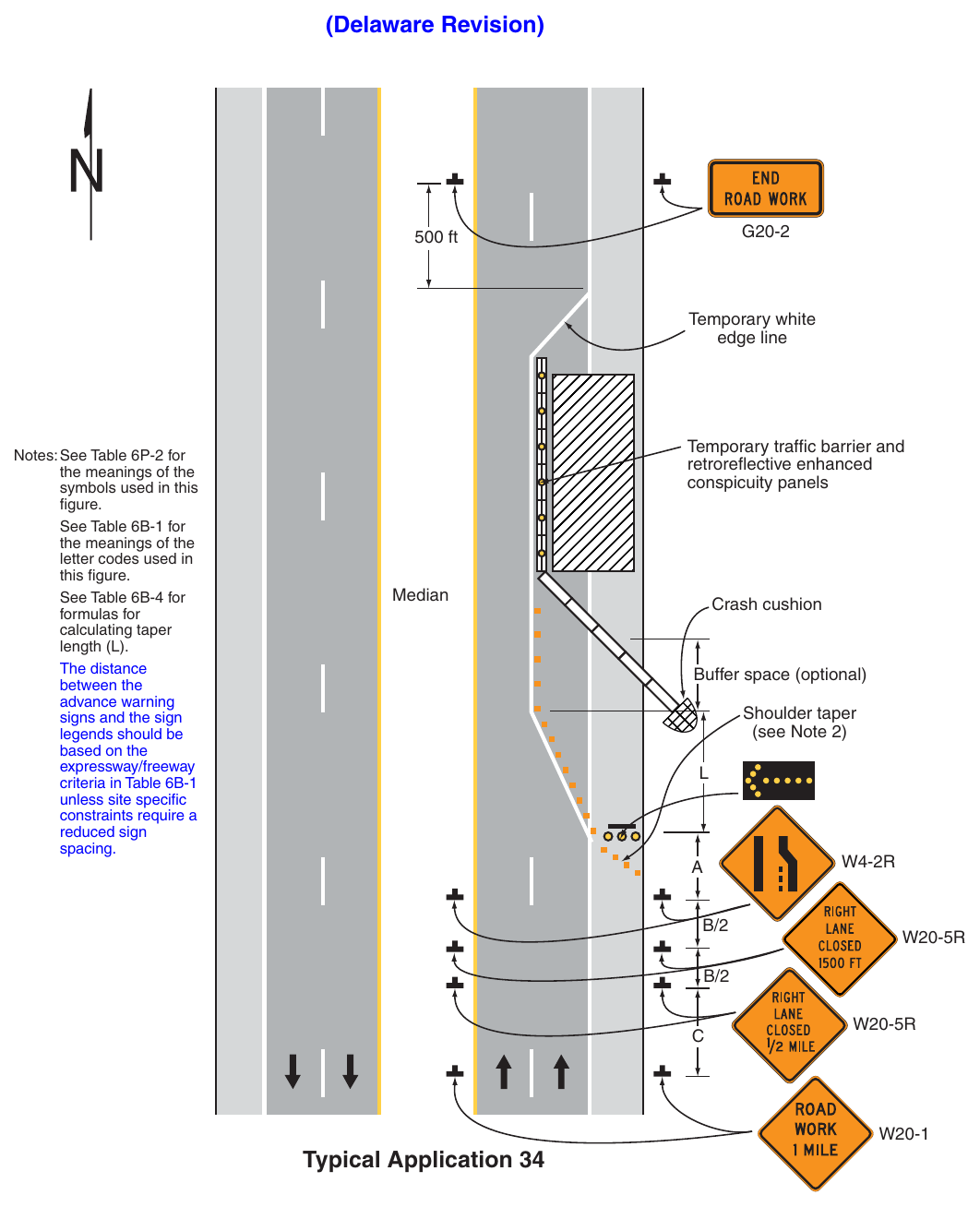
(Delaware Revision) 500 ft Temporary white edge line Notes: See Table 6P-2 for the meanings of the symbols used in this figure. See Table 6B-1 for the meanings of the letter codes used in this figure. See Table 6B-4 for formulas for calculating taper length (L). The distance between the advance warning signs and the sign legends should be based on the expressway/freeway criteria in Table 6B-1 unless site specific constraints require a reduced sign spacing. retroreflective enhanced conspicuity panels Crash cushion Buffer space (optional) Shoulder taper (see Note 2) Typical Application 34 Notes for Figure 6P-35—Typical Application 35 (Delaware Revision)
Standard
- 1. Arrow boards shall, as a minimum, be Type B, with a size of 60 x 30 inches.
- 2. Vehicle-mounted signs shall be mounted in a manner such that they are not obscured by equipment or supplies. Sign legends on vehicle-mounted signs shall be covered or turned from view when work is not in progress.
- 3. Shadow and work vehicles shall display high-intensity rotating, flashing, oscillating, or strobe lights.
- 4. An arrow board shall be used when a lane is closed. When more than one lane is closed, a separate arrow board shall be used for each closed lane.
Guidance
- 5. Vehicles used for these operations should be made highly visible with appropriate equipment, such as signs, or arrow boards.
- 6. Shadow Vehicle 1 should be equipped with an arrow board and truck-mounted attenuator.
- 7. Shadow Vehicle 2 should be equipped with an arrow board. An appropriate lane closure sign should be placed on Shadow Vehicle 2 so as not to obscure the arrow board.
- 8. Shadow Vehicle 2 should travel at a varying distance from the work operation so as to provide adequate sight distance for vehicular traffic approaching from the rear.
- 9. The spacing between the work vehicles and the shadow vehicles, and between each shadow vehicle, should be minimized to deter road users from driving in between.
- 10. Work should normally be accomplished during off-peak hours.
- 11. When the work vehicle occupies an interior lane (a lane other than the far right or far left) of a directional roadway having a right-hand shoulder 10 feet or more in width, Shadow Vehicle 2 should drive on the right-hand shoulder with a sign indicating that work is taking place in the interior lane.
Option
- 12. A truck-mounted attenuator may be used on Shadow Vehicle 2.
- 13. Positive protection devices may be used per Section 6M.02.
- 14. On high-speed roadways, a third shadow vehicle (not shown) may be used with Shadow Vehicle 1 in the closed lane, Shadow Vehicle 2 straddling the edge line, and Shadow Vehicle 3 on the shoulder.
- 15. Where adequate shoulder width is not available, Shadow Vehicle 3 may also straddle the edge line.
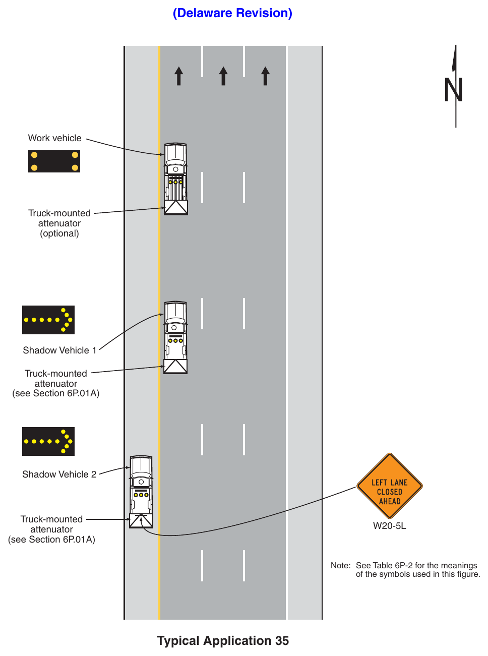
Signs shown: W20-5L
(Delaware Revision) Work vehicle Truck-mounted attenuator (optional) Shadow Vehicle 1 Truck-mounted attenuator (see Section 6P.01A) Shadow Vehicle 2 Truck-mounted attenuator (see Section 6P.01A) Note: See Table 6P-2 for the meanings of the symbols used in this figure. Typical Application 35 Notes for Figure 6P-35A—Typical Application 35A Short Duration and Mobile Operations on a Freeway with a Single Lane Closure (Delaware Revision)
Standard
- 1. This TTC zone application also shall be used when work is being performed in the lane adjacent to the median on a divided highway. In this case, the LEFT LANE CLOSED AHEAD sign shall be substituted.
- 2. Arrow boards on the shadow vehicles shall, at a minimum, be Type B, with a size of 60 x 30 inches.
- 3. If used, vehicle-mounted signs shall be mounted in a manner such that they are not obscured by equipment or supplies. Sign legends on vehicle-mounted signs shall be covered or turned from view when work is not in progress.
- 4. Shadow and work vehicles shall display high-intensity rotating, flashing, oscillating, or strobe lights.
- 5. An arrow board shall be used when a lane is closed.
Guidance
- 6. Vehicles used for these operations should be made highly visible with appropriate equipment, such as signs or arrow boards.
- 7. Work should normally be accomplished during off-peak hours.
- 8. Whenever adequate stopping sight distance exists to the rear, the shadow vehicles should maintain the minimum distance from the preceding vehicle and proceed at the same speed. The shadow vehicles should slow down in advance of vertical or horizontal curves that restrict sight distance.
- 9. If used, Shadow Vehicle 4 should be located upstream of queued traffic to advise motorists of the potential for stopped vehicles.
Option
- 10. Shadow vehicle 4 may be used where adequate shoulder width is available to display a portable changeable message sign.
- 11. Positive protection devices may be used per Section 6M.02.
- 12. A downstream vehicle may be used ahead of the work areas as depicted in Figure 6P-35. If used, the downstream vehicle may be equipped with a truck-mounted attenuator.
Support
- 13. The purpose of a downstream vehicle within the lane closure ahead of the work area is to provide a longitudinal buffer space ahead of the work area to prevent erratic lane changes by motor vehicle traffic downstream of the work area.
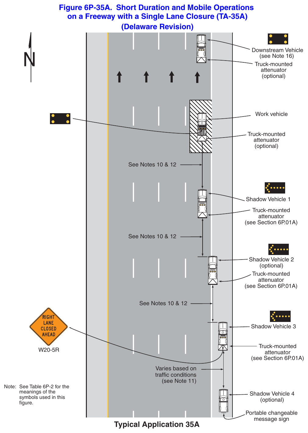
Standard
- 1. This TTC zone application also shall be used when work is being performed in the lanes adjacent to the median on a divided highway. In this case, the 2 LEFT LANES CLOSED AHEAD sign shall be substituted.
- 2. Arrow boards on the shadow vehicles shall, at a minimum, be Type B, with a size of 60 x 30 inches.
- 3. If used, vehicle-mounted signs shall be mounted in a manner such that they are not obscured by equipment or supplies. Sign legends on vehicle-mounted signs shall be covered or turned from view when work is not in progress.
- 4. Shadow and work vehicles shall display high-intensity rotating, flashing, oscillating, or strobe lights.
- 5. An arrow board shall be used when a lane is closed. When more than one lane is closed, a separate arrow board shall be used for each closed lane.
Guidance
- 6. Vehicles used for these operations should be made highly visible with appropriate equipment, such as signs, or arrow boards.
- 7. Work should normally be accomplished during off-peak hours.
- 8. Shadow vehicle 1A should be used for stationary short duration operations only.
- 9. Whenever adequate stopping sight distance exists to the rear, the shadow vehicles should maintain the minimum distance from the preceding vehicle and proceed at the same speed. The shadow vehicles should slow down in advance of vertical or horizontal curves that restrict sight distance.
- 10. If used, Shadow Vehicle 6 should be located upstream of queued traffic to advise motorists of the potential for stopped vehicles.
Option
- 11. The minimum distance between the shadow vehicles may vary according to terrain and other factors, such as the manufacturer’s recommendations for the truck-mounted attenuator.
- 12. Shadow vehicle 6 may be used where adequate shoulder width is available to display a portable changeable message sign.
- 13. Positive protection devices may be used per Section 6M.02.
- 14. A downstream vehicle may be used ahead of the work areas as depicted in Figure 6P-35B. If used, the downstream vehicle may be equipped with a truck-mounted attenuator.
Support
- 15. Shadow vehicles are used to warn motor vehicle traffic of the operation ahead. References to truckmounted attenuators are also applicable to tow-behind or trailer attenuators.
- 16. The purpose of a downstream vehicle within the lane closure ahead of the work area is to provide a longitudinal buffer space ahead of the work area to prevent erratic lane changes by motor vehicle traffic downstream of the work area.
Standard
- 17. When the operation requires the closure of more than two travel lanes, two additional shadow vehicles and Truck-mounted attenuators per Section 6P.01A shall be added to the operation per lane. One vehicle shall be placed between the closed lane and the lane to be closed. The second vehicle shall be placed in the additional closed lane. The advance warning sign on Shadow Vehicle 5 shall be modified to indicate the number of closed lanes.
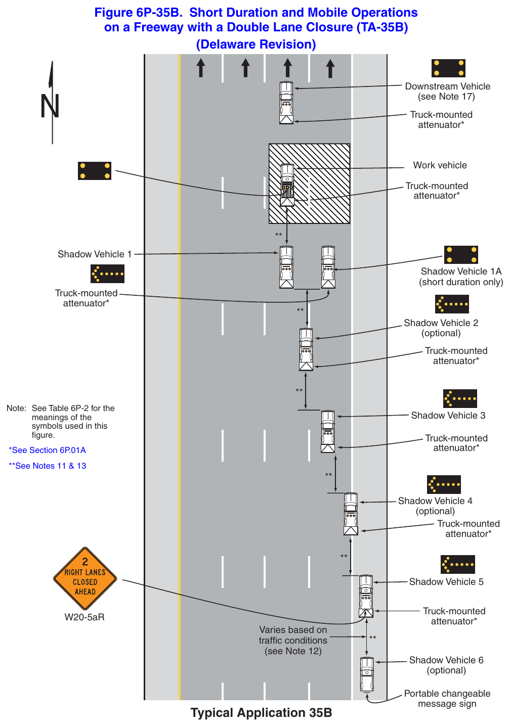
Standard
- 1. If used, the use of temporary traffic barrier affecting state-maintained roadways shall be based on a design approved by DelDOT Traffic. The design shall include length of need calculations, taper layouts, determination of deflection needs, typical sections, and provisions of runout areas.
Guidance
- 2. The lane shift should be used when the work space extends into either the right-hand or left-hand lane of a divided highway and it is impracticable, for capacity reasons, to reduce the number of available lanes.
Option
- 3. The barrier shown in this typical application is an example of one method that may be used to close a shoulder for a long-term project requiring a lane shift.
Standard
- 4. Temporary traffic barriers, if used, shall comply with the provisions of Section 6M.02.
- 5. The barrier shall not be placed along the shifting taper. The lane shall first be shifted using channelizing devices and pavement markings.
Guidance
- 6. Where drivers emerging from an intersecting roadway will not encounter an advance warning sign prior to the work zone, additional signs should be placed on the intersecting road.
- 7. A warning sign should be used to show the changed alignment.
- 8. Advisory Speed plaques should be used only when the advisory speed is less than the posted speed limit.
Standard
- 9. Except as provided in Note 10 below, the number of lanes illustrated on the Reverse Curve signs shall be the same as the number of through lanes available to road users, and the direction of the reverse curves shall be appropriately illustrated.
Option
- 10. Where two or more lanes are being shifted, a W1-4 (or W1-3) sign with an ALL LANES (W24-1cP) plaque (see Figure 6H-1) may be used instead of a sign that illustrates the number of lanes.
- 11. Where more than three lanes are being shifted, the Reverse Curve (or Turn) sign may be rectangular.
Guidance
- 12. If the tangent distance along the temporary diversion is less than 600 feet, a Double Reverse Curve sign should be used instead of the upstream Reverse Curve sign, and the downside Reverse Curve sign should be omitted.
- 13. If a STAY IN LANE sign is used, then solid white lane lines should be used.
Standard
- 14. The minimum width of the shoulder lane shall be 10 feet.
- 15. For long-term stationary work, existing conflicting pavement markings shall be removed and temporary markings shall be installed before traffic patterns are changed.
Option
- 16. For short-term stationary work, lanes may be delineated by channelizing devices or removable pavement markings instead of temporary markings.
Guidance
- 17. If the shoulder cannot adequately accommodate trucks, trucks should be directed to use the travel lanes.
- 18. The use of a barrier should be based on engineering judgment.
- 19. A shifting taper length of L is preferred on state-maintained roads (see Tables 6B-3 and 6B-4).
Option
- 20. Shift areas may be illuminated at night, except in emergencies.
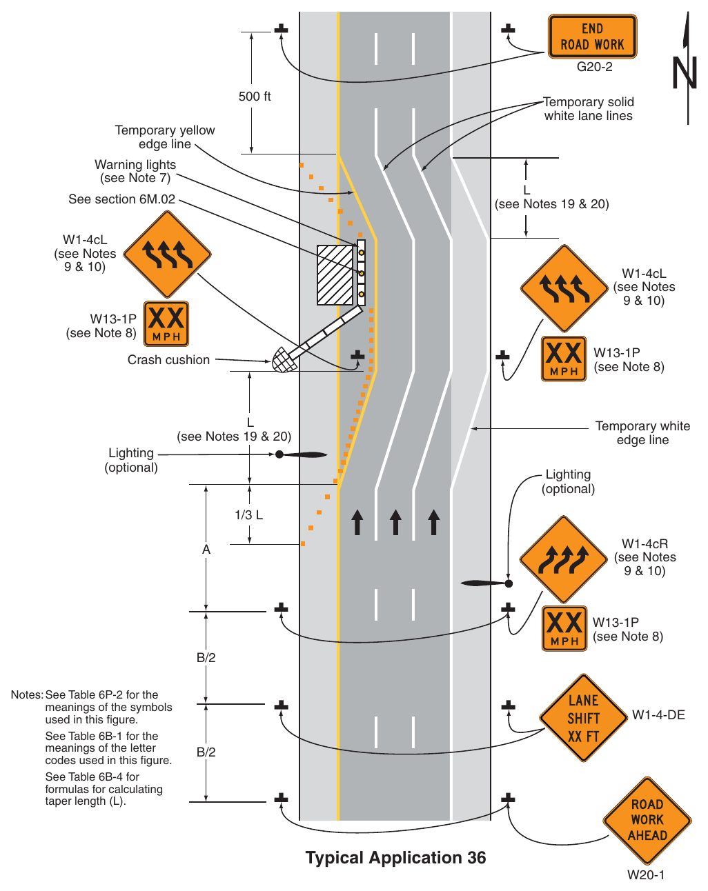
Standard
- 1. This TTC zone application also shall be used when work is being performed in the lanes adjacent to the median on a multi-lane, divided highway. In this case, the 2 LEFT LANES CLOSED signs and the corresponding Lane Ends signs shall be substituted.
- 2. An arrow board shall be used when a lane is closed. When more than one lane is closed, a separate arrow board shall be used for each closed lane.
Guidance
- 3. Where drivers emerging from an intersecting roadway will not encounter an advance warning sign prior to the work zone, additional signs should be placed on the intersecting road.
- 4. The second arrow board should be placed in the closed exterior lane at the upstream end of the second merging taper.
- 5. When paved shoulders are closed, channelizing devices should be used to close the shoulder in advance of the merging taper to direct vehicular traffic to remain within the traveled way.
Option
- 6. Positive protection devices may be used per Section 6M.02.
Standard
- 7. When the work operation requires more than 2 lanes be closed, each additional lane to be closed shall be closed by providing a tangent distance of 2L starting at the end of the previous merging taper to the beginning of the next merging taper, placement of the MERGE warning sign within the 2L tangent space and placement of an arrow board in each additional closed lane. The advance lane closure warning signs shall be modified to indicate the number of lanes closed.
Guidance
- 8. For roadways with posted speed limits of 40 mph or less, the typical application shown in Figure 6P-37 should be modified as follows:
- a. Sign spacing should be based on Table 6B-1 for urban high-speed or low-speed conditions, dependent upon the posted speed limit,
- b. Taper lengths should be based on the posted speed limit,
- c. The tangent length between merging tapers should be reduced to L, and
- d. Instead of displaying distances on the advance warning signs, use the legend AHEAD.
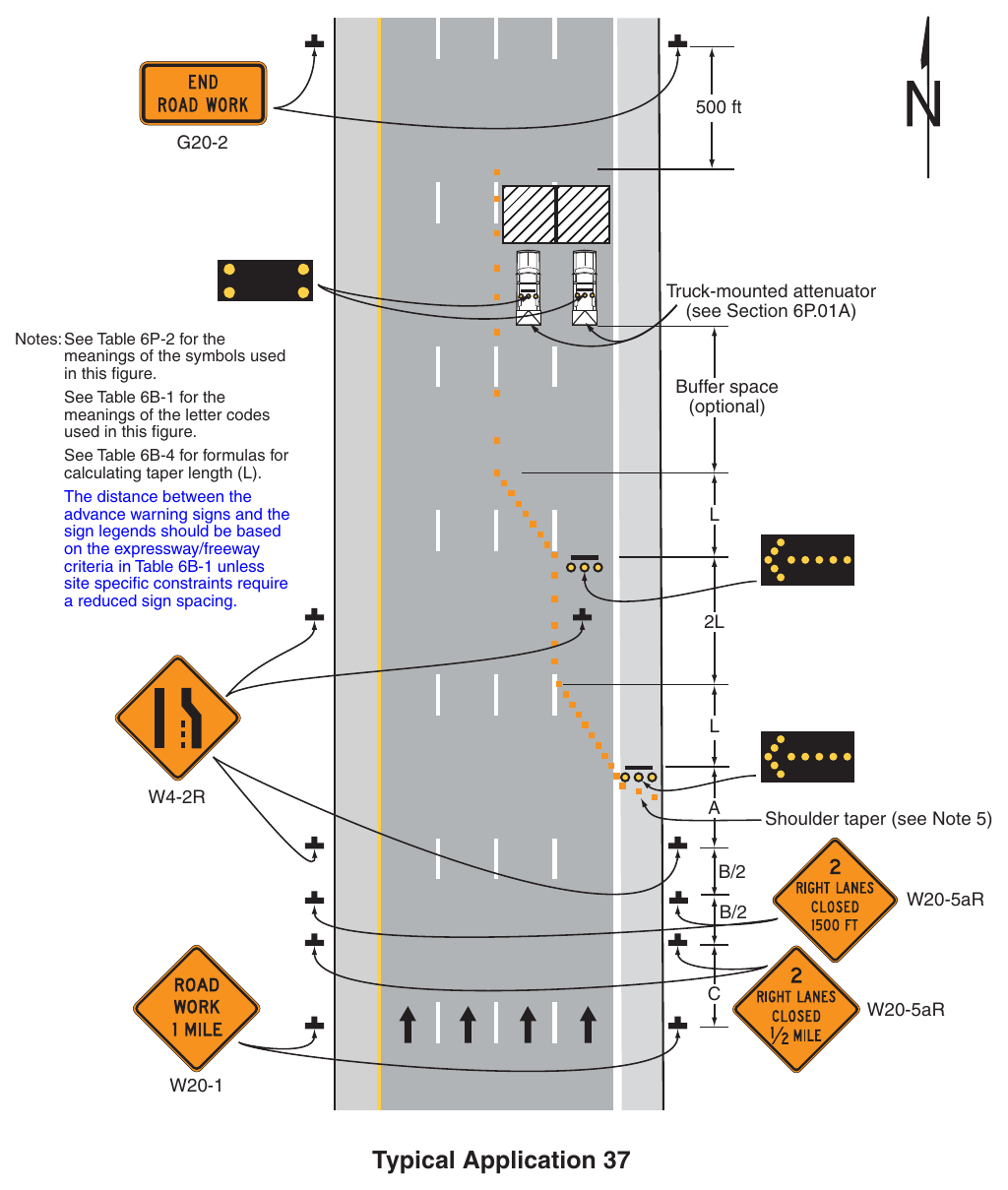
(Delaware Revision) 500 ft Truck-mounted attenuator (see Section 6P.01A) Notes: See Table 6P-2 for the meanings of the symbols used in this figure. See Table 6B-1 for the meanings of the letter codes used in this figure. See Table 6B-4 for formulas for calculating taper length (L). The distance between the advance warning signs and the sign legends should be based on the expressway/freeway criteria in Table 6B-1 unless site specific constraints require a reduced sign spacing. Buffer space (optional)
2L. L Shoulder taper (see Note 5) W20-5aR W20-5aR Typical Application 37 Notes for Figure 6P-38—Typical Application 38 Interior Lane Closure on a Multi-Lane, Divided Highway and Freeway (Delaware Revision)
Standard
- 1. The use of this Typical Application on state-maintained roads shall be approved by DelDOT Traffic.
Guidance
- 2. Use of this TTC zone application is strongly discouraged because of worker safety and driver expectancy concerns associated with permitting high-speed traffic on both sides of the work space. When an interior lane is closed, an adjacent lane should also be considered for closure to provide additional space for vehicles and materials and to facilitate the movement of equipment within the work space. The method for closing an interior lane when the open lanes have the capacity to carry vehicular traffic should be as shown in Figure 6P-37, instead of as shown in this TTC zone application.
Standard
- 3. An arrow board shall be used when a lane is closed. When more than one lane is closed, a separate arrow board shall be used for each closed lane.
- 4. If temporary traffic barriers are installed, they shall comply with the provisions and requirements in Section 6M.02.
- 5. If used, Tthe barrier shall not be placed along the shifting taper. The lane shall first be shifted using channelizing devices and pavement markings.
- 6. For long-term stationary work, existing conflicting pavement markings shall be removed and temporary markings shall be installed before traffic patterns are changed.
Guidance
- 7. Where drivers emerging from an intersecting roadway or ramp will not encounter an advance warning sign prior to the work zone, additional signs should be placed on the intersecting road.
- 8. For a long-term closure, a barrier should be used to provide additional safety to the operation in the closed interior lane. A buffer space should be used at the upstream end of the closed interior lane.
- 9. An arrow board displaying an arrow pointing to the right should be placed on the left-hand shoulder at the beginning of the taper.
- 10. If the two arrow boards create confusion, the 2L distance between the end of the merging taper and beginning of the shifting taper should be extended so that road users can focus on one arrow board
- 11. The placement of signs should not obstruct or obscure arrow boards.
- 12. For long-term use, the broken lane lines should be made solid white in the two-lane section.
- 13. A short, single row of channelizing devices in advance of the vehicular traffic split to restrict vehicular traffic to their respective lanes should be added. When channelizing devices have the potential of leading vehicular traffic out of the intended traffic space, the channelizing devices should be extended a distance in feet of 2 times the speed limit in mph beyond the downstream end of the transition area as depicted in Figure 6P-38.
- 14. When paved shoulders are closed, channelizing devices should be used to close the shoulder in advance of the merging taper to direct vehicular traffic to remain within the traveled way.
Option
- 15. As an alternative to initially closing the left-hand lane, as shown in the typical TTC zone application, the right-hand lane may be closed in advance of the interior lane closure with appropriate channelization and signs. The Interior Lane Shift Ahead symbol sign may be mirrored to indicate a right lane shift.
A short, single row of channelizing devices in advance of the vehicular traffic split to restrict vehicular
- 16. DO NOT PASS signs may be used.
- 17. If a paved shoulder having a minimum width of 10 feet and sufficient strength is available, the left-hand and center lanes may be closed and motor vehicle traffic carried around the work space on the right-hand
- 18. Positive protection devices may be used per Section 6M.02.
- 19. Shift areas may be illuminated at night, except in emergencies.
Guidance
- 20. When a shoulder lane is used that cannot adequately accommodate trucks, trucks should be directed to use the normal travel lanes.
- 21. A shifting taper length of L is preferred on state-maintained roads (see Tables 6B-3 and 6B-4).
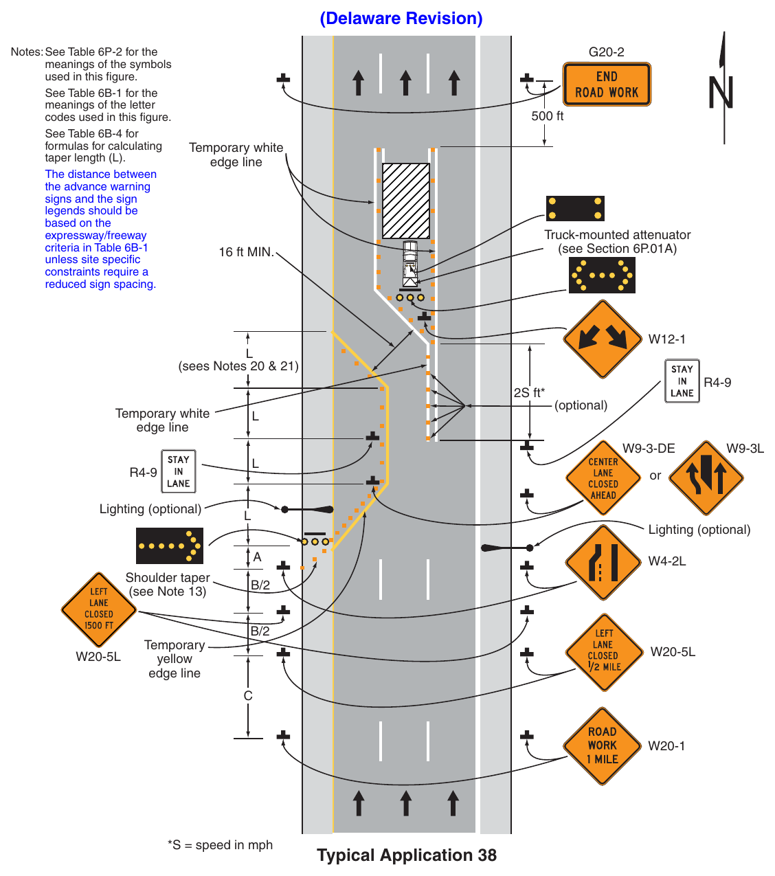
(Delaware Revision) Notes: See Table 6P-2 for the meanings of the symbols used in this figure. See Table 6B-1 for the meanings of the letter codes used in this figure. See Table 6B-4 for formulas for calculating taper length (L). The distance between the advance warning signs and the sign legends should be based on the expressway/freeway criteria in Table 6B-1 unless site specific constraints require a reduced sign spacing. 500 ft Temporary white edge line Truck-mounted attenuator (see Section 6P.01A) 16 ft MIN. (sees Notes 20 & 21) 2S ft Temporary white edge line Lighting (optional) yellow edge line Lighting (optional) Shoulder taper (see Note 13) (optional) S = speed in mph Typical Application 38 Notes for Figure 6P-39—Typical Application 39 Median Crossover on a Multi-Lane, Divided Highway and Freeway (Delaware Revision)
Standard
- 1. The use of this Typical Application on state-maintained roads shall be approved by DelDOT Traffic.
- 2. Channelizing devices or temporary traffic barriers shall be used to separate opposing vehicular traffic.
- 3. An arrow board shall be used when a lane is closed. When more than one lane is closed, a separate arrow board shall be used for each closed lane.
Guidance
- 4. For long-term work on high-speed, high-volume highways, consideration should be given to using a temporary traffic barrier to separate opposing vehicular traffic.
Option
- 5. When a temporary traffic barrier is used to separate opposing vehicular traffic, the Two-Way Traffic, Do Not Pass, KEEP RIGHT, and DO NOT ENTER signs may be eliminated.
- 6. The alignment of the crossover may be designed as a reverse curve.
Guidance
- 7. When the crossover follows a curved alignment, the design criteria contained in the “AASHTO Green Book – A Policy On Geometric Design Of Highways And Streets,” 7th Edition, 2018, AASHTO should be used.
- 8. When channelizing devices have the potential of leading vehicular traffic out of the intended traffic space, the channelizing devices should be extended a distance in feet of 2 times the speed limit in mph beyond the downstream end of the transition area as depicted.
- 9. Where channelizing devices are used, the Two-Way Traffic signs should be repeated every 1 mile.
Option
- 10. NEXT XX MILES Supplemental Distance plaques may be used with the Two-Way Traffic signs, where XX is the distance to the downstream end of the two-way section.
Support
- 11. When the distance is sufficiently short that road users entering the section can see the downstream end of the section, they are less likely to forget that there is opposing vehicular traffic.
- 12. The sign legends for the four pairs of signs approaching the lane closure for the non-crossover direction of travel are not shown. They are similar to the series shown for the crossover direction, except that the left-hand lane is closed.
Option
- 13. Positive protection devices may be used per Section 6M.02.
- 14. Shift areas may be illuminated at night, except in emergencies.
Guidance
- 15. A shifting taper length of L is preferred on state-maintained roads (see Tables 6B-3 and 6B-4).
- 16. Advisory Speed plaques should be used only when the advisory speed is less than the posted speed limit.
- 17. Where drivers emerging from an intersecting roadway will not encounter an advance warning sign prior to the work zone, additional signs should be placed on the intersecting road.
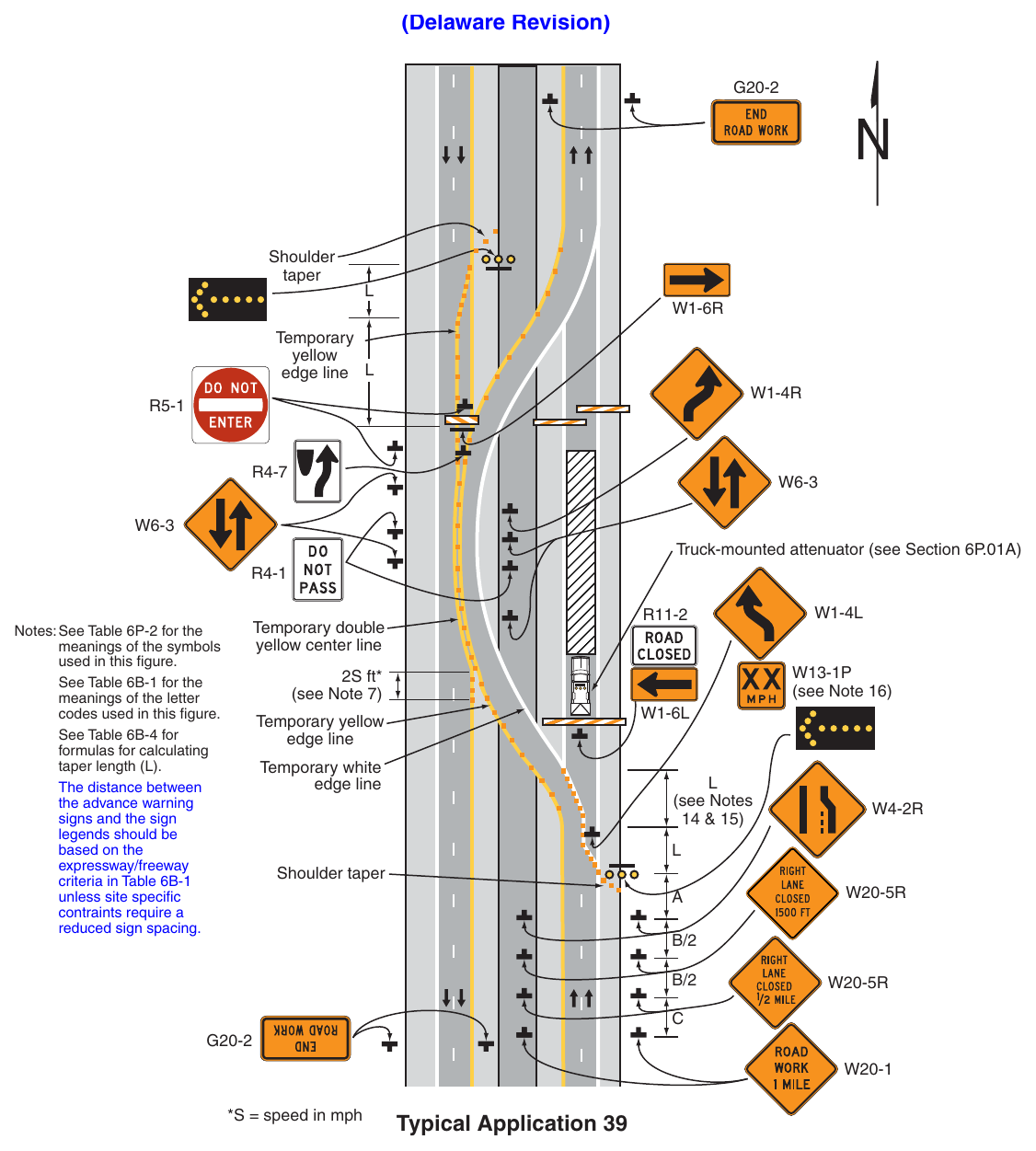
Signs shown: G20-2, W1-6R, W1-4R, R5-1, R4-7, W6-3, R4-1, R11-2, W1-4L, W13-1P, W1-6L, W4-2R, W20-5R
Standard
- 1. The use of this Typical Application on state-maintained roads shall be approved by DelDOT Traffic.
Guidance
- 2. The typical TTC zone application illustrated should be used for carrying an entrance ramp across a closed directional roadway of a divided highway.
- 3. A temporary acceleration lane should be used to facilitate merging. The design criteria contained in the latest edition of the AASHTO “Policy on the Geometric Design of Highways and Streets” (see Section 1A.11) should be used for determining the acceleration lane length.
- 4. When used, the YIELD or STOP sign should be located far enough forward to provide adequate sight distance of oncoming mainline vehicular traffic to select an acceptable gap, but should not be located so far forward that motorists will be encouraged to stop in the path of the mainline traffic. If needed, yield or stop lines should be installed across the ramp to indicate the point at which road users should yield or stop. Also, a longer acceleration lane should be provided beyond the sign to reduce the gap size needed.
- 5. Where STOP signs are used, a temporary stop line should be placed across the ramp at the desired stop location.
Option
- 6. Positive protection devices may be used per Section 6M.02.
- 7. If vehicular traffic conditions allow, the ramp may be closed.
Standard
- 8. Except as provided in Note 9, entrance ramp closures along state-maintained roadways shall have a detour plan approved by DelDOT Traffic.
Option
- 9. A detour plan may not be needed for entrance ramp closures during off-peak, short-duration, or mobile
- 10. A broken edge line may be carried across the temporary entrance ramp to assist in defining the through vehicular traffic lane.
- 11. When a temporary traffic barrier is used to separate opposing vehicular traffic, the Two-Way Traffic signs and the DO NOT ENTER signs may be eliminated.
- 12. A Stop Beacon (see Section 4S.05) may be placed above the STOP sign.
- 13. Where the acceleration distance is significantly reduced, a NO MERGE AREA supplemental plaque may be placed below the Yield Ahead sign.
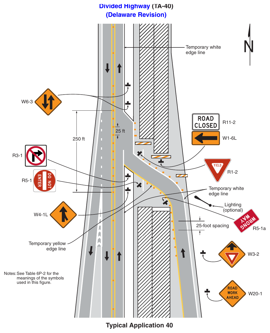
Signs shown: W6-3, R11-2, W1-6L, R3-1, R1-2, R5-1, W4-1L, R5-1a, W3-2, W20-1
(Delaware Revision) Temporary white edge line 25 ft 250 ft Temporary white edge line Lighting (optional) 25-foot spacing Temporary yellow edge line R5-1a Notes: See Table 6P-2 for the meanings of the symbols used in this figure. Notes for Figure 6P-41—Typical Application 41 Median Crossover for an Exit Ramp on a Multi-Lane, Divided Highway and Freeway (Delaware Revision)
Standard
- 1. The use of this Typical Application on state-maintained roads shall be approved by DelDOT Traffic.
Guidance
- 2. This typical TTC zone application should be used for carrying an exit ramp across a closed directional roadway of a divided highway. The design criteria contained in the “AASHTO Green Book – A Policy On Geometric Design Of Highways And Streets,” 7th Edition, 2018, AASHTO should be used for determining the curved alignment.
- 3. The guide signs should indicate that the ramp is open, and where the temporary ramp is located. Conversely, if the ramp is closed, guide signs should indicate that the ramp is closed.
- 4. When the exit is closed, a black-on-orange EXIT CLOSED sign panel should be placed diagonally across the interchange/intersection guide signs and channelizing devices should be placed to physically close the ramp.
- 5. In the situation (not shown) where channelizing devices are placed along the mainline roadway, the devices’ spacing should be reduced in the vicinity of the off ramp to emphasize the opening at the ramp itself. Channelizing devices and/or temporary pavement markings should be placed on both sides of the temporary ramp where it crosses the median and the closed roadway.
- 6. Advance guide signs providing information related to the temporary exit should be relocated or duplicated adjacent to the temporary roadway.
Standard
- 7. A temporary EXIT sign shall be located in the temporary gore. For better visibility, it shall be mounted a minimum of 7 feet from the pavement surface to the bottom of the sign.
Option
- 8. Positive protection devices may be used per Section 6M.02.
- 9. Guide signs referring to the exit may need to be relocated to the median.
- 10. The temporary EXIT sign placed in the temporary gore may be either black on orange or white on green.
- 11. In some instances, a temporary deceleration lane may be useful in facilitating the exiting maneuver.
- 12. When a temporary traffic barrier is used to separate opposing vehicular traffic, the Two-Way Traffic signs may be omitted.
- 13. If vehicular traffic conditions allow, the ramp may be closed.
Standard
- 14. Except as provided in Note 15, exit ramp closures along state-maintained roadways shall have a detour plan approved by DelDOT Traffic.
Option
- 15. A detour plan may not be needed for exit ramp closures during off-peak, short-duration, or mobile
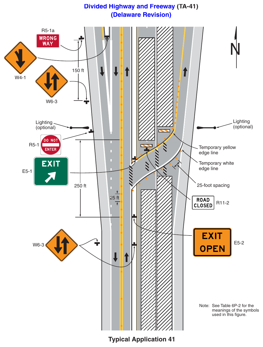
(Delaware Revision) R5-1a 150 ft Lighting (optional) Lighting (optional) Temporary yellow edge line Temporary white edge line 25-foot spacing 250 ft 25 ft Note: See Table 6P-2 for the meanings of the symbols used in this figure. Typical Application 41 Notes for Figure 6P-42—Typical Application 42 Work in the Vicinity of an Exit Ramp (Delaware Revision)
Standard
- 1. The use of this Typical Application on state-maintained roads shall be approved by DelDOT Traffic.
Guidance
- 2. The guide signs should indicate that the ramp is open, and where the temporary ramp is located. However, if the ramp is closed, guide signs should indicate that the ramp is closed.
- 3. When the exit ramp is closed, a black-on-orange EXIT CLOSED sign panel should be placed diagonally across the interchange/intersection guide signs.
- 4. The design criteria contained in the “AASHTO Green Book – A Policy On Geometric Design Of Highways and Streets,” 7th Edition, 2018, AASHTO should be used for determining the alignment.
Standard
- 5. A temporary EXIT sign shall be located in the temporary gore. For better visibility, it shall be mounted a minimum of 7 feet from the pavement surface to the bottom of the sign.
Option
- 6. Positive protection devices may be used per Section 6M.02.
- 7. The temporary EXIT sign placed in the temporary gore may be either black on orange or white on green.
An alternative procedure that may be used is to channelize exiting vehicular traffic onto the right-hand
Standard
- 8. An arrow board shall be used when a lane is closed. When more than one lane is closed, a separate arrow board shall be used for each closed lane.
Guidance
- 9. Where drivers emerging from an intersecting roadway or entrance ramp will not encounter an advance warning sign prior to the work zone, additional signs should be placed on the intersecting road or
- 10. Truck off-tracking should be considered when determining whether the minimum lane width of 12 feet is adequate (see Section 6N.07).
Option
- 11. If vehicular traffic conditions allow, the ramp may be closed, as determined by DelDOT Traffic.
Standard
- 12. Except as provided in Note 13, exit ramp closures along state-maintained roadways shall have a detour plan approved by DelDOT Traffic.
Option
- 13. A detour plan may not be needed for exit ramp closures during off-peak, short-duration, or mobile
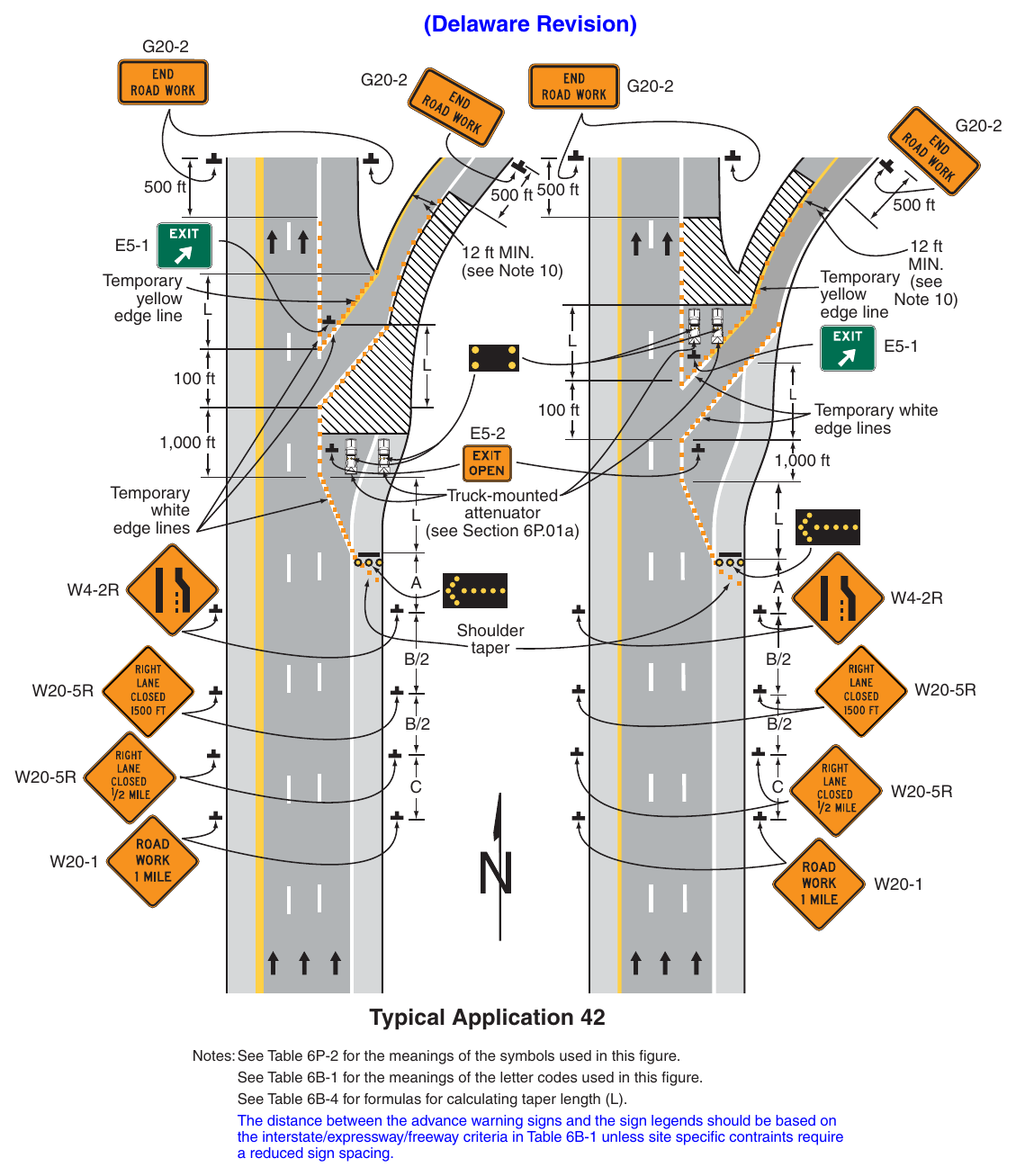
(Delaware Revision) 500 ft 500 ft 500 ft yellow edge line 500 ft 12 ft yellow Note 10) edge line 12 ft MIN. (see Note 10) 100 ft Temporary white edge lines 100 ft 1,000 ft white edge lines 1,000 ft Truck-mounted attenuator (see Section 6P.01a) taper Typical Application 42 Notes: See Table 6P-2 for the meanings of the symbols used in this figure. See Table 6B-1 for the meanings of the letter codes used in this figure. See Table 6B-4 for formulas for calculating taper length (L). The distance between the advance warning signs and the sign legends should be based on the interstate/expressway/freeway criteria in Table 6B-1 unless site specific contraints require a reduced sign spacing. Notes for Figure 6P-43—Typical Application 43 (Delaware Revision)
Guidance
- 1. Truck off-tracking should be considered when determining whether the minimum lane width of 10 feet is adequate (see Section 6N.07).
Option
- 2. Positive protection devices may be used per Section 6M.02.
- 3. If vehicular traffic conditions allow, the ramp may be closed, as determined by DelDOT Traffic.
Standard
- 4. Except as provided in Note 5, exit ramp closures along state-maintained roadways shall have a detour plan approved by DelDOT Traffic.
Option
- 5. A detour plan may not be needed for exit ramp closures during off-peak, short-duration, or mobile
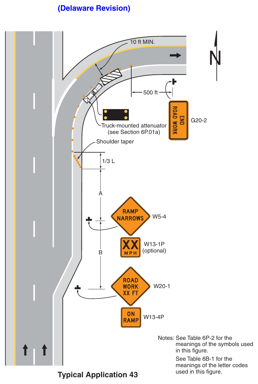
(Delaware Revision) 10 ft MIN. 500 ft Truck-mounted attenuator (see Section 6P.01a) Shoulder taper (optional) Typical Application 43 Notes: See Table 6P-2 for the meanings of the symbols used in this figure. See Table 6B-1 for the meanings of the letter codes used in this figure. Notes for Figure 6P-44—Typical Application 44 Work in the Vicinity of an Entrance Ramp (Delaware Revision)
Standard
- 1. The use of this Typical Application on state-maintained roads shall be approved by DelDOT Traffic.
Guidance
An acceleration lane of sufficient length should be provided whenever possible as shown on the diagram
- 2. On the right diagram, a temporary acceleration lane should be used to facilitate ramp merging. The design criteria contained in the latest edition of the AASHTO “Policy on the Geometric Design of Highways and Streets” (see Section 1A.11) should be used for determining the acceleration lane length.
Standard
- 3. For the information shown on the diagram on the right-hand side of the typical application, where inadequate acceleration distance exists for the temporary entrance, the YIELD sign shall be replaced with STOP signs (one on each side of the approach).
Guidance
- 4. When used, the YIELD or STOP sign should be located so that ramp vehicular traffic has adequate sight distance of oncoming mainline vehicular traffic to select an acceptable gap in the mainline vehicular traffic flow, but should not be located so far forward that motorists will be encouraged to stop in the path of the mainline traffic. Also, a longer acceleration lane should be provided beyond the sign to reduce the gap size needed. If sufficient gaps are not available, consideration should be given to closing the ramp.
- 5. Where a STOP sign is used, a temporary stop line should be placed across the ramp at the desired stop location.
- 6. The mainline merging taper with the arrow board at its starting point should be located sufficiently in advance so that the arrow board is not confusing to drivers on the entrance ramp, and so that the mainline merging vehicular traffic from the lane closure has the opportunity to stabilize before encountering the vehicular traffic merging from the ramp.
- 7. If the ramp curves sharply to the right, warning signs with advisory speeds located in advance of the entrance terminal should be placed in pairs (one on each side of the ramp).
Option
- 8. Positive protection devices may be used per Section 6M.02.
- 9. A Stop Beacon (see Section 4S.05) may be placed above the STOP sign.
- 10. Where the acceleration distance is significantly reduced, a supplemental plaque may be placed below the Yield Ahead sign reading NO MERGE AREA.
Standard
- 11. An arrow board shall be used when a lane is closed. When more than one lane is closed, a separate arrow board shall be used for each closed lane.
Guidance
- 12. Where drivers emerging from an intersecting road or entrance ramp will not encounter an advance warning sign prior to the work zone, additional signs should be placed on the intersecting road or
- 13. Truck off-tracking should be considered when determining whether the minimum lane width of 12 feet is adequate (see Section 6N.07).
Option
- 14. If vehicular traffic conditions allow, the ramp may be closed, as determined by DelDOT Traffic.
Standard
- 15. Except as provided in Note 16, exit ramp closures along state-maintained roadways shall have a detour plan approved by DelDOT Traffic.
Option
- 16. A detour plan may not be needed for exit ramp closures during off-peak, short-duration, or mobile
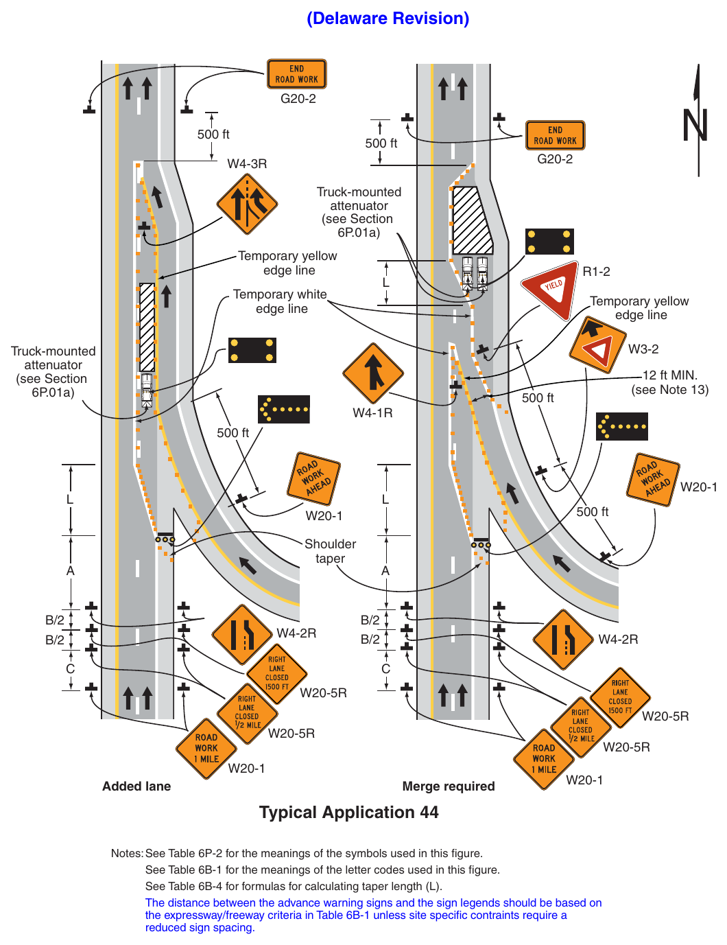
Signs shown: G20-2, W4-3R, R1-2, W3-2, W4-1R, W20-1, W4-2R, W20-5R
(Delaware Revision) 500 ft 500 ft Truck-mounted attenuator 6P.01a) Temporary yellow edge line Temporary white edge line Temporary yellow edge line Truck-mounted attenuator 6P.01a) 12 ft MIN. (see Note 13) 500 ft 500 ft 500 ft taper Added lane Merge required Typical Application 44 Notes: See Table 6P-2 for the meanings of the symbols used in this figure. See Table 6B-1 for the meanings of the letter codes used in this figure. See Table 6B-4 for formulas for calculating taper length (L). The distance between the advance warning signs and the sign legends should be based on the expressway/freeway criteria in Table 6B-1 unless site specific contraints require a reduced sign spacing. Notes for Figure 6P-45—Typical Application 45 (Delaware Revision)
Standard
- 1. The use of this Typical Application on state-maintained roads shall be approved by DelDOT Traffic.
Support
- 2. This application addresses one of several uses for movable barriers (see Section 6M.02) in highway TTC zones. In this example, one side of a 6-lane divided highway is closed to perform the work operation, and vehicular traffic is carried in both directions on the remaining 3-lane roadway by means of a median To accommodate unbalanced peak-period vehicular traffic volumes, the direction of travel in the center lane is switched to the direction having the greater volume, with the transfer typically being made twice daily. Thus, there are four vehicular traffic phases described as follows:
- a. Phase A—two travel lanes northbound and one lane southbound;
- b. Transition A to B—one travel lane in each direction;
- c. Phase B—one travel lane northbound and two lanes southbound; and
- d. Transition B to A—one travel lane in each direction. The typical application on the left illustrates the placement of devices during Phase A. The typical application on the right shows conditions during the transition (Transition A to B) from Phase A to Phase B.
Guidance
- 3. For the reversible lane situation depicted, the ends of the movable barrier should terminate in a protected area or a crash cushion should be provided. During Phase A, the transfer vehicle should be parked behind the downstream end of the movable barrier for southbound traffic as shown in the typical application on the left. During Phase B, the transfer vehicle should be parked between the downstream ends of the movable barriers at the north end of the TTC zone as shown in the typical application on the right. The transition shift from Phase A to B should be as follows:
- a. Change the signs in the northbound advance warning area and transition area from a LEFT LANE CLOSED AHEAD to a 2 LEFT LANES CLOSED AHEAD. Change the mode of the second northbound arrow board from Caution to Right Arrow.
- b. Place channelizing devices to close the northbound center lane.
- c. Move the transfer vehicle from south to north to shift the movable barrier from the west side to the east side of the reversible lane.
- d. Remove the channelizing devices closing the southbound center lane.
- e. Change the signs in the southbound transition area and advance warning area from a 2 LEFT LANES CLOSED AHEAD to a LEFT LANE CLOSED AHEAD. Change the mode of the second southbound arrow board from Right Arrow to Caution.
- 4. Where the lane to be opened and closed is an exterior lane (adjacent to the edge of the traveled way or the work space), the lane closure should begin by closing the lane with channelizing devices placed along a merging taper using the same information employed for a stationary lane closure. The lane closure should then be extended with the movable-barrier transfer vehicle moving with vehicular traffic. When opening the lane, the transfer vehicle should travel against vehicular traffic. The merging taper should be removed in a method similar to a stationary lane closure.
Option
- 5. The procedure may be used during a peak period of vehicular traffic and then changed to provide two lanes in the other direction for the other peak.
- 6. A longitudinal buffer space may be used in the activity area to separate opposing vehicular traffic.
- 7. A work vehicle or a shadow vehicle may be equipped with a truck-mounted attenuator.
Standard
- 8. An arrow board shall be used when a freeway lane is closed. When more than one freeway lane is closed, a separate arrow board shall be used for each closed lane.
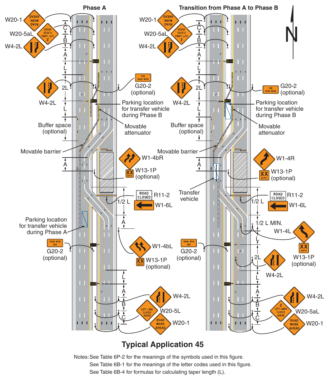
Signs shown: W20-1, W4-2L, G20-2, W1-4R, W13-1P, R11-2, W1-6L, W1-4L, W20-5L
Notes: See Table 6P-2 for the meanings of the symbols used in this figure. See Table 6B-1 for the meanings of the letter codes used in this figure. See Table 6B-4 for formulas for calculating taper length (L). Notes for Figure 6P-46—Typical Application 46 Work in the Vicinity of a Grade Crossing (Delaware Revision)
Guidance
- 1. When grade crossings exist either within or in the vicinity of roadway work activities, extra care should be taken to minimize the probability of conditions being created, by lane restrictions, flagging, or other operations, where vehicles might be stopped within the grade crossing, considered as being 15 feet on either side of the closest and farthest rail.
- 2. When a grade crossing exists within or upstream of the transition area and it is anticipated that queues resulting from the lane closure might extend through the grade crossing, the TTC zone should be extended so that the transition area precedes the grade crossing.
- 3. When a grade crossing exists within the activity area, drivers operating on the left-hand side of the normal center line should be provided with comparable warning devices as for drivers operating on the right-hand side of the normal center line.
Standard
- 4. If the queuing of vehicles across active rail tracks cannot be avoided, a uniformed law enforcement officer or flagger shall be provided at the grade crossing to prevent vehicles from stopping within the grade crossing (as described in Note 1 above), even if automatic warning devices are in place.
Guidance
- 5. When a grade crossing equipped with active warning devices exists within the activity area, provisions should be made for keeping flaggers informed as to the activation status of these warning devices.
- 6. Early coordination with the railroad company or transit agency should occur before work starts.
- 7. In the example depicted, the buffer space of the activity area should be extended upstream of the grade crossing (as shown) so that a queue created by the flagging operation will not extend across the
- 8. The DO NOT STOP ON TRACKS sign should be used on all approaches to a grade crossing within the limits of a TTC zone.
- 9. Where drivers emerging from an intersecting roadway will not encounter an advance warning sign prior to the work zone, additional signs should be placed on the intersecting road.
Option
- 10. Positive protection devices may be used per Section 6M.02.
- 11. A BE PREPARED TO STOP sign may be added to the sign series.
- 12. Automated Flagger Assistance Devices (see Section 6L.02) may be used in situations where there is only one lane of approaching traffic in the direction to be controlled.
Guidance
- 13. When used, the BE PREPARED TO STOP sign should be located before the Flagger symbol sign.
Standard
- 14. At night, flagger stations shall be illuminated, except in emergencies.
- 15. If the operation requires using a truck-mounted attenuator upstream of the grade crossing, the truck-mounted attenuator’s roll-ahead buffer space shall not extend across the grade crossing.
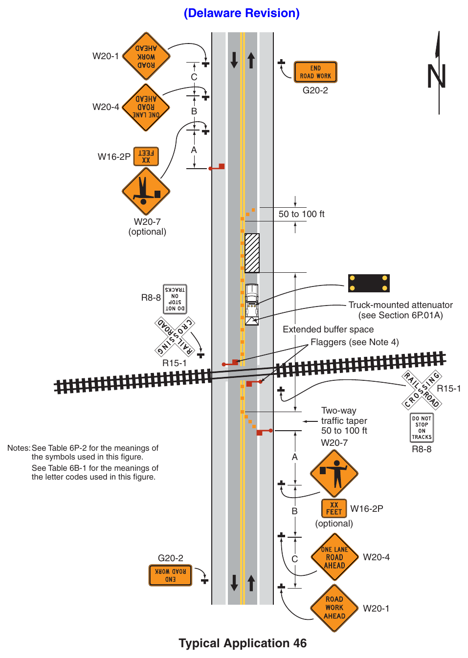
Signs shown: W20-1, G20-2, W20-4, W16-2P, W20-7, R8-8, R15-1
(Delaware Revision) 50 to 100 ft (optional) Truck-mounted attenuator (see Section 6P.01A) Extended buffer space Flaggers (see Note 4) Two-way traffic taper 50 to 100 ft Notes: See Table 6P-2 for the meanings of the symbols used in this figure. See Table 6B-1 for the meanings of the letter codes used in this figure. (optional) Typical Application 46 Notes for Figure 6P-47—Typical Application 47
Guidance
- 1. If a bicycle lane on a roadway having a speed limit of 35 mph or higher is closed and conditions are not appropriate to direct bicyclists into a shared lane, a separate bicycle facility or detour route should be considered (see Figures 6P-48 and 6P-51).
Option
- 2. If a bicycle lane on a roadway having a speed limit of 30 mph or less is closed, and the adjacent travel lane is less than 14 feet wide, then BICYCLES ALLOWED USE OF FULL LANE signs may be used.
- 3. If a bicycle lane on a roadway having a speed limit of 30 mph or less is closed, and the adjacent travel lane is at least 14 feet wide throughout the TTC zone, then Bicycle Warning signs in association with IN STREET or IN ROADWAY plaques may be used.
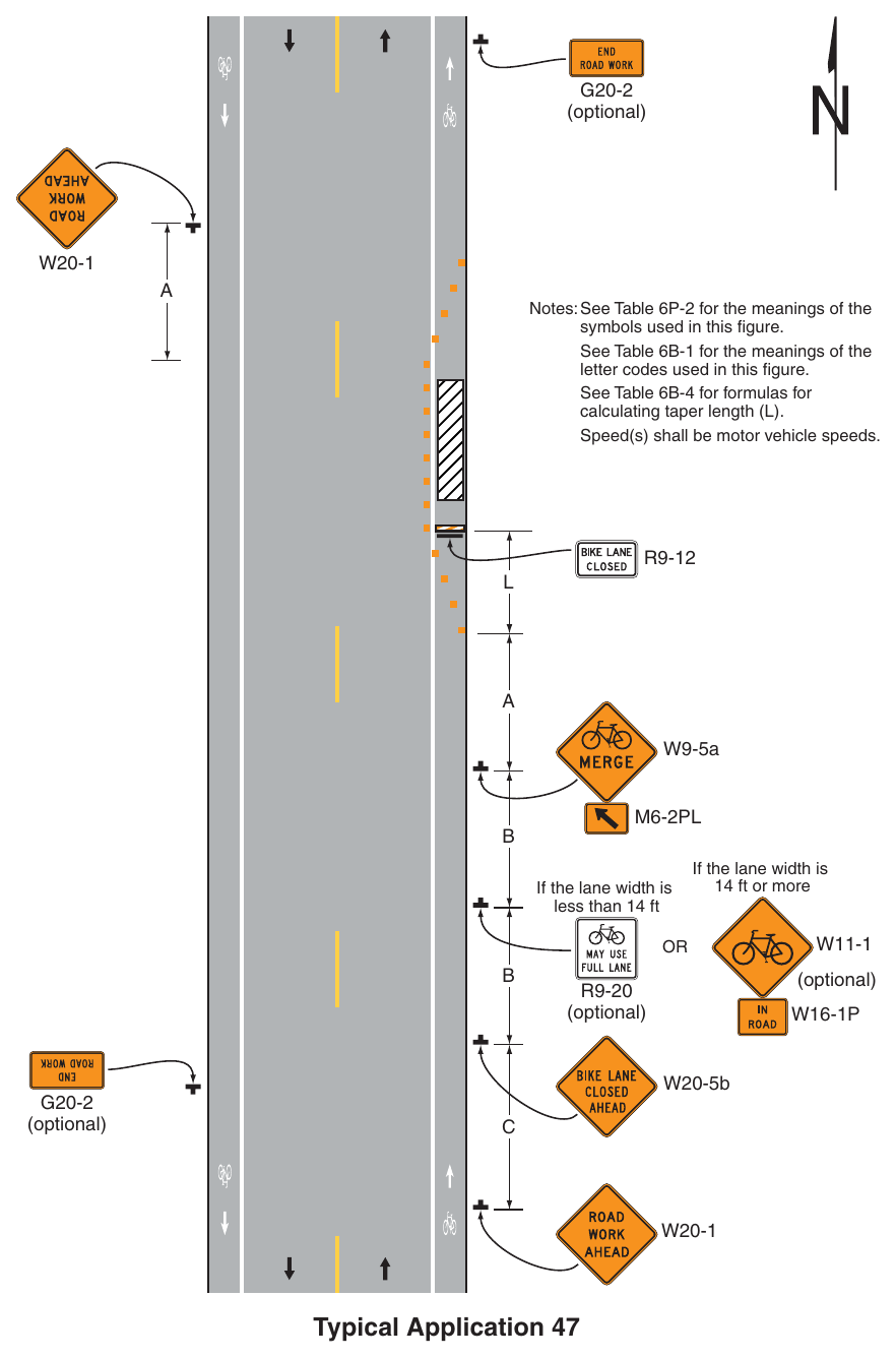
Signs shown: G20-2, W20-1, R9-12, W9-5a, W11-1, R9-20, W16-1P, W20-5b
Notes: See Table 6P-2 for the meanings of the symbols used in this figure. See Table 6B-1 for the meanings of the letter codes used in this figure. See Table 6B-4 for formulas for calculating taper length (L). Speed(s) shall be motor vehicle speeds. W9-5a If the lane width is less than 14 ft If the lane width is 14 ft or more (optional) (optional) W20-5b (optional) Typical Application 47 Notes for Figure 6P-48—Typical Application 48 Bicycle Lane Closure with an On-Road Detour (Delaware Revision)
Guidance
- 1. A detour route for bicyclists where a section of bicycle lane is closed should use the most direct route practical on roadways or shoulders where conditions are appropriate for bicycling.
- 2. Bicycle related regulatory and/or warning signs should be considered along the bicycle detour based on engineering judgment and traffic conditions.
- 3. A Street Name sign or Bike Route Name sign should be mounted with the Bike Detour sign.
Option
- 4. The Street Name sign or Bike Route Name sign may be either white on green or black on orange.
Standard
- 5. Where used, the Street Name sign or Bike Route Name sign shall be placed above the Bike Detour sign.
Option
- 6. If a bicycle lane on a roadway having a speed limit of 30 mph or less is closed, and the adjacent travel lane is less than 14 feet wide, then BICYCLES ALLOWED USE OF FULL LANE signs may be used along the entire route unless a dedicated bicycle lane is present.
- 7. If a bicycle lane on a roadway having a speed limit of 30 mph or less is closed, and the adjacent travel lane is at least 14 feet wide throughout the TTC zone, then Bicycle Warning signs in association with IN STREET or IN ROADWAY plaques may be used.
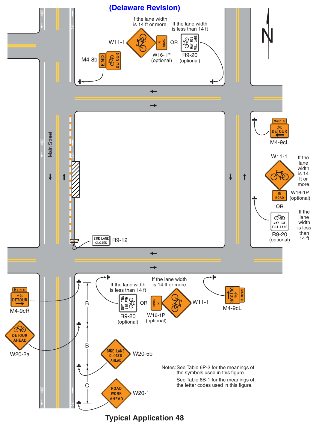
Signs shown: M4-8b, R9-12, W20-2a, W20-5b, W20-1, W11-1, W16-1P, R9-20
(Delaware Revision) If the lane width is 14 ft or more If the lane width is less than 14 ft (optional) (optional) Main Street M4-8b M4-9cL If the width is 14 ft or (optional) (optional) If the lane width is less than 14 ft If the lane width is 14 ft or more M4-9cR (optional) If the width is less 14 ft M4-9cL (optional) W20-5b W20-2a Notes: See Table 6P-2 for the meanings of the symbols used in this figure. See Table 6B-1 for the meanings of the letter codes used in this figure. Typical Application 48 Notes for Figure 6P-49—Typical Application 49 (Delaware Revision)
Guidance
- 1. The temporary paved shared-use path should be at least as wide as the shared-use path that was temporarily closed.
- 2. The temporary paved shared-use path should be designed in accordance with Section 6C.02 and 6C.03.
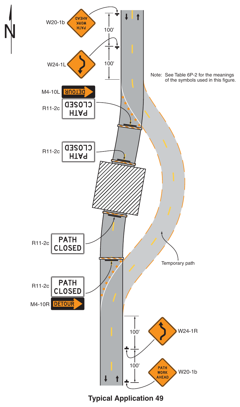
Note: See Table 6P-2 for the meanings of the symbols used in this figure. R11-2c R11-2c R11-2c R11-2c W20-1b Typical Application 49 Notes for Figure 6P-50—Typical Application 50 (Delaware Revision)
Standard
- 1. All detours along state-maintained roadways or shared-use paths shall have a detour plan approved by DelDOT Traffic.
Guidance
- 2. Temporary traffic control for pedestrian movements should be in accordance with Figures 6P28 or 6P-29.
- 3. The on-road detour route for bicyclists should use the most direct route practical on roadways or shoulders where conditions are appropriate for bicycling.
- 4. Bicycle related regulatory and/or warning signs should be considered along the bicycle detour based on engineering judgment and traffic conditions.
- 5. A Street Name sign or Bike Route Name sign should be mounted with the Bike Detour sign.
- 6. The Bike Route Name sign should be mounted with the Bike Detour sign when there are overlapping vehicular or shared-use path detour routes, or when additional guidance is needed to avoid road user confusion.
Option
- 7. The Street Name sign or Bike Route Name sign may be either white on green or black on orange.
Standard
- 8. Where used, the Street Name sign or Bike Route Name sign shall be placed above the Bike Detour sign.
Option
- 9. If a bicycle lane on a roadway having a speed limit of 30 mph or less is closed, and the adjacent travel lane is less than 14 feet wide, then BICYCLES ALLOWED USE OF FULL LANE signs may be used.
- 10. If a bicycle lane on a roadway having a speed limit of 30 mph or less is closed, and the adjacent travel lane is at least 14 feet wide throughout the TTC zone, then Bicycle Warning signs in association with IN STREET or IN ROADWAY plaques may be used.
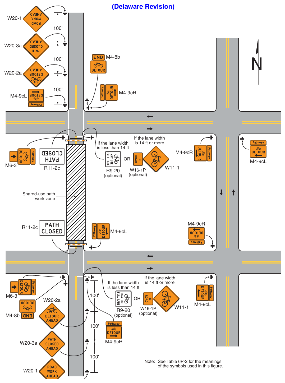
Signs shown: W20-1, W20-3a, M4-8b, W20-2a, M6-3, R11-2c, W11-1, R9-20, W16-1P
(Delaware Revision) W20-3a M4-8b W20-2a M4-9cR M4-9cL If the lane width is less than 14 ft If the lane width is 14 ft or more M4-9cR R11-2c (optional) M4-9cL (optional) M4-9cR R11-2c M4-9cL If the lane width is less than 14 ft W20-2a (optional) M4-8b If the lane width is 14 ft or more (optional) M4-9cL M4-9cR W20-3a Note: See Table 6P-2 for the meanings of the symbols used in this figure.
50. Notes for Figure 6P-51—Typical Application 51 Paved Shoulder Closure with a Bicycle Diversion onto a Temporary Path (Delaware Revision)
Option
- 1. This plan may be used where a paved shoulder is closed and a temporary paved path is provided for bicyclists.
Guidance
- 2. This plan should be used where a paved shoulder is closed on a roadway having a speed limit of 45 mph or greater that is part of a bikeway system (local, county or state) and a temporary paved path is provided for bicyclists.
- 3. The A, B, and C dimensions should be based on anticipated bicycle speeds.
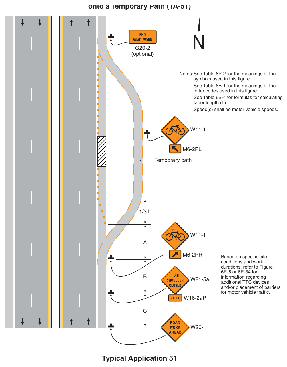
G20-2 (optional) Notes: See Table 6P-2 for the meanings of the symbols used in this figure. See Table 6B-1 for the meanings of the letter codes used in this figure. See Table 6B-4 for formulas for calculating taper length (L). Speed(s) shall be motor vehicle speeds. W21-5a W16-2aP Based on specific site conditions and work durations, refer to Figure 6P-5 or 6P-34 for information regarding additional TTC devices and/or placement of barriers for motor vehicle traffic. Typical Application 51 Notes for Figure 6P-52—Typical Application 52 Short-Term or Short-Duration Work in a Circular Intersection (Delaware Revision)
Option
- 1. Flashing warning lights and/or flags may be used to call attention to the advance warning signs. A BE PREPARED TO STOP sign may be added to the sign series.
- 2. If closure continues overnight, warning lights may be used on the channelizing devices.
Standard
- 3. Where a quadrant of the circular intersection is closed, only one direction of approach traffic shall be released at a time.
- 4. At night, flagger stations shall be illuminated, except in emergencies.
- 5. WRONG WAY signs shall be covered.
Guidance
- 6. When used, the BE PREPARED TO STOP sign should be located between the Flagger sign and the ONE LANE ROAD sign.
- 7. YIELD, ONE WAY, and Directional arrow signs should be covered or removed.
- 8. Confusing or misleading guide or lane-use control signs should be covered.
Option
- 9. Crosswalks may be closed.
- 10. As an alternative to closing crosswalks, warning signs may be added informing pedestrians that there is traffic coming from the left.
Guidance
- 11. Since the geometrics of the circular intersection will be temporarily altered, consideration should be given to establishing a truck detour for the duration of the project.
- 12. For intermediate or long-term work, the circular intersection should be closed and traffic detoured, with appropriate detour signing (see Figure 6P-8) provided.
- 13. When crosswalks within a circular intersection are closed, accommodations for pedestrian should be implemented following Sections 6C.02 and 6C.03.
Option
- 14. A portable changeable message sign may be used as part of the TTC plan to provide clear guidance to motorists on all approaches to the circular intersection.
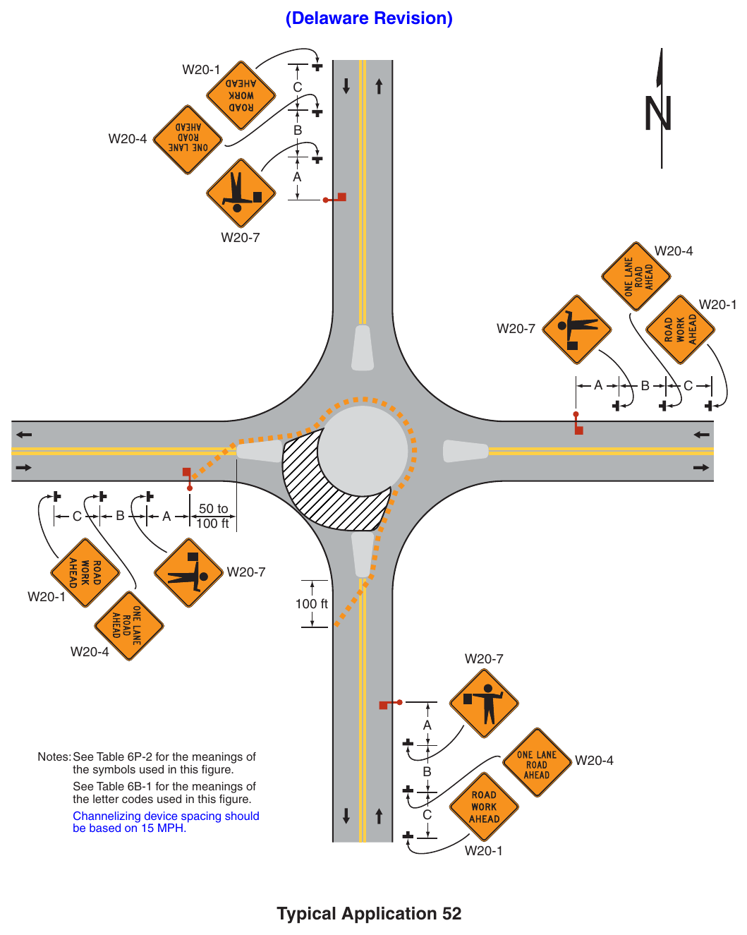
(Delaware Revision) 50 to 100 ft 100 ft Notes: See Table 6P-2 for the meanings of the symbols used in this figure. See Table 6B-1 for the meanings of the letter codes used in this figure. Channelizing device spacing should be based on 15 MPH. Typical Application 52 Notes for Figure 6P-53—Typical Application 53 Flagging Operation on a Single-Lane Circular Intersection (Delaware Revision)
Support
- 1. Each roundabout is unique, and the temporary traffic control must be developed to meet the specific conditions of the location and the work operation. A detour could possibly better serve traffic movement and be considered as an alternative to the flagging operation depicted in Figure 6P-53 with the approval of DelDOT Traffic.
Standard
- 2. Flaggers shall control traffic flow on all approaches of the single-lane roundabout and shall follow the procedures provided in Sections 6D.05 and 6D.06.
- 3. A lead flagger shall be designated, and approved communication devices shall be used by all flaggers.
- 4. When crosswalks or other pedestrian facilities are closed or relocated, temporary facilities (see Figure 6P-29) shall be detectable and shall include accessibility features consistent with the features present in the existing pedestrian facility.
- 5. At night, flagger stations shall be illuminated, except in emergencies.
- 6. Portable Changeable Message Signs (PCMS) shall be used on any approach where traffic is required to move to the left or right of a splitter island. PCMS messages affecting state-maintained roadways shall be approved by DelDOT Traffic.
Option
- 7. A supplemental flagger may be used in the central island of the roundabout to help direct traffic.
- 8. A BE PREPARED TO STOP sign may be added to the sign series.
Guidance
- 9. When used, the BE PREPARED TO STOP sign should be located between the Flagger symbol sign and the ONE LANE ROAD sign.
- 10. Flaggers on each approach to the intersection should coordinate with each other so that traffic proceeds through the circular intersection from only one entry point at any one time.
- 11. When designing the TTC and installing the channelizing devices for work activities at circular intersections, accommodations for the turning radius of wider heavy commercial vehicles should be considered.
- 12. Since the geometrics of the circular intersection will temporarily be altered, consideration should be given to establishing a truck detour for the duration of the project.
- 13. For intermediate or long-term work, the circular intersection should be closed if traffic cannot be accommodated, and traffic detoured with appropriate detour signing (see Figure 6P-8) provided.
- 14. Conflicting pavement markings should be removed for long-term projects. For short-term and intermediate-term projects where this is impracticable, the channelizing devices in the area where the pavement markings conflict should be placed at a maximum spacing of ½ S feet where S is the advisory speed in mph of the circulatory roadway. Temporary markings should be installed where needed.
- 15. The buffer space should be extended so that the two-way traffic taper is placed before a horizontal (or crest vertical) curve to provide adequate sight distance for the flagger and a queue of stopped vehicles.
- 16. Care should be exercised when establishing the limits of the TTC zone to ensure adequate sight distance in advance of the transition.
- 17. Since the geometrics of the circular intersection will be temporarily altered, consideration should be given to establishing a truck detour for the duration of the project.
- 18. When working within two or more quadrants of the circulatory roadway, the intersection should be closed and traffic detoured around the closure, the following the principles of Figure 6P-20.
- 19. Where drivers emerging from an intersecting roadway will not encounter an advance warning sign prior to the work zone, additional signs should be placed on the intersecting road.
Standard
- 20. If used, a detour affecting state-maintained roadways shall be approved by DelDOT Traffic.
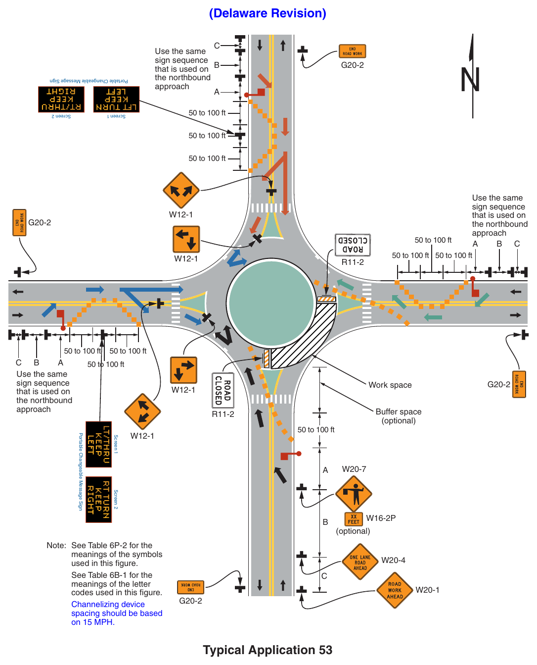
Signs shown: G20-2, W12-1, R11-2, W20-7, W16-2P, W20-4, W20-1
(Delaware Revision) Use the same sign sequence that is used on B the northbound approach Portable Changeable Message Sign 50 to 100 ft Screen 1 Screen 2 50 to 100 ft 50 to 100 ft 50 to 100 ft 50 to 100 ft Use the same sign sequence that is used on the northbound approach Use the same sign sequence that is used on the northbound approach 50 to 100 ft 50 to 100 ft 50 to 100 ft 50 to 100 ft Work space Buffer space (optional) Screen 1 Screen 2 Portable Changeable Message Sign 50 to 100 ft Note: See Table 6P-2 for the meanings of the symbols used in this figure. See Table 6B-1 for the meanings of the letter codes used in this figure. Channelizing device spacing should be based on 15 MPH. (optional) Typical Application 53 Notes for Figure 6P-54—Typical Application 54 Inside Lane Closure on a Multi-Lane Circular Intersection (Delaware Revision)
Standard
- 1. When crosswalks or other pedestrian facilities are closed or relocated, temporary facilities (see Figure 6P-29) shall be detectable and shall include accessibility features consistent with the features present in the existing pedestrian facility.
Guidance
- 2. Care should be exercised when establishing the limits of the TTC zone to ensure adequate sight distance in advance of the transition.
- 3. When designing the TTC and installing the channelizing devices for work activities at circular intersections, accommodations for the turning radius of wider heavy commercial vehicles should be considered.
- 4. Since the geometrics of the circular intersection will temporarily be altered, consideration should be given to establishing a truck detour for the duration of the project.
- 5. For intermediate or long-term work, the circular intersection should be closed if traffic cannot be accommodated, and traffic detoured with appropriate detour signing provided (see Figure 6P-8).
- 6. Conflicting pavement markings should be removed for long-term projects. For short-term and intermediate-term projects where this is impracticable, the channelizing devices in the area where the pavement markings conflict should be placed at a maximum spacing of ½ S feet where S is the advisory speed of the circulatory roadway in mph. Temporary markings should be installed where needed.
Option
- 7. A portable changeable message sign may be used as part of the TTC plan to provide clear guidance to motorists on all approaches to the circular intersection.
- 8. On a multi-lane approach, a lane (or lanes) on either the left-hand side or the right-hand side may be closed.
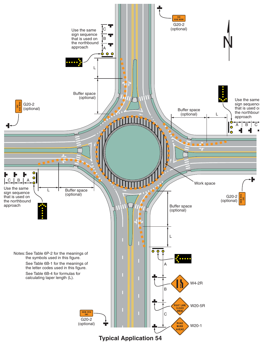
Notes: See Table 6P-2 for the meanings of the symbols used in this figure. See Table 6B-1 for the meanings of the letter codes used in this figure. See Table 6B-4 for formulas for calculating taper length (L). (optional) Typical Application 54