2H–2N. Miscellaneous Signs¶
Chapter 2H. GENERAL INFORMATION SIGNS¶
§2H.01 Scope¶
Support
01. General Information signs provide road users with navigational or orientation, geographic, or other information useful for traffic operational purposes. They include such items as State lines, city limits, other political boundaries, time zones, river names, elevations, landmarks, and similar geographic features. Chapter 2M contains recreational and cultural interest area symbol signs that are sometimes used in combination with General Information Signs. Section 1D.09 contains information on unnecessary traffic control devices. Section 2A.20 contains information on the excessive use of signs and sign clutter.
Option
02. A General Information (I3-5 through I4-2) symbol sign (see Figure 2H-1) may be used to provide direction to a transportation (I3 series signs) or other (I4 series signs) facility. The symbol sign may be supplemented by an educational plaque where necessary. The name of the facility may be used, if needed, to distinguish between similar facilities in the same area.
03. The Advance Turn (M5 series) or Directional Arrow (M6 series) auxiliary plaques (see Figure 2H-1) with white arrows on green backgrounds may be used with General Information symbol signs to create a General Information Directional Assembly.
04. The Recycling Center (I4-2) symbol sign may be used to direct road users to recycling centers.
Guidance
05. The Recycling Center symbol sign should not be used on freeways and expressways.
Option
06. The Passengers Only Ferry Terminal (I3-10) symbol sign may be used with the FERRY (I3-10P) plaque (see Figure 2H-1) mounted below it in a directional assembly to direct road users to passenger-only ferry terminals.
Guidance
07. General Information signs should not be installed within a series of guide signs, or at other equally critical locations, unless there are specific reasons for orienting the road user or identifying control points for activities that are clearly in the public interest. On all such signs, the designs should be simple and dignified, devoid of any tendency toward advertising, such as complex graphics or unnecessary messages, and in general compliance with other guide signing.
Standard
08. Promotional descriptive messages that are not relevant to navigation and orientation, such as “Scenic” or “Historic,” shall not be included in the legends of General Information signs, except as otherwise provided in this Chapter or in cases in which these terms are part of an official name, such as for a Scenic Byway or Historic District.
09. Except for State Welcome signs (see Section 2H.07), Acknowledgment signs (see Section 2H.13), and Alternative Fuels Corridor signs (see Section 2H.14), General Information signs shall have white legends and borders on green rectangular-shaped backgrounds.
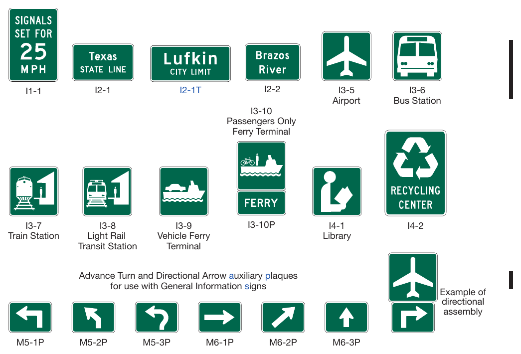
Signs shown: I1-1, I2-1, I2-1T, I2-2, I3-5, I3-6, I3-10, I3-7, I3-8, I3-9, I3-10P, I4-1, I4-2, M5-1P, M5-2P, M5-3P, M6-1P, M6-2P, M6-3P
§2H.02 Sizes of General Information Signs¶
Standard
01. Except as provided in Section 2A.07, the sizes of General Information signs that have a standardized design shall be as shown in Table 2H-1.
Support
02. Section 2A.07 contains information regarding the applicability of the various columns in Table 2H-1.
Option
03. Signs larger than those shown in Table 2H-1 may be used (see Section 2A.07), except where a maximum allowable size is specified.
Table 2H-1. General Information Sign and Plaque Sizes
| Sign | Sign Designation | Section | Conventional Road | Freeway or Expressway |
|---|---|---|---|---|
| Next EV Charging | D9-17a | 2H.14, 2J.06 | — | 126 x 60 |
| Alternative Fuels Corridor | D9-19 | 2H.14 | 24 x 24 | 36 x 36 |
| Alternative Fuels Corridor (1 line) (plaque) | D9-19aP | 2H.14 | 30 x 9 | 42 x 12 |
| Alternative Fuels Corridor (2 lines) (plaque) | D9-19bP | 2H.14 | 30 x 12 | 42 x 18 |
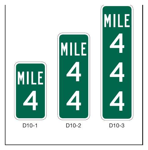
| Reference Location (1 digit) | D10-1 | 2H.11 | 10 x 18 | 12 x 24 |
| Intermediate Reference Location (2 digits) | D10-1a | 2H.11 | 10 x 27 | 12 x 36 |
| Reference Location (2 digits) | D10-2 | 2H.11 | 10 x 27 | 12 x 36 |
| Intermediate Reference Location (3 digits) | D10-2a | 2H.11 | 10 x 36 | 12 x 48 |
| Reference Location (3 digits) | D10-3 | 2H.11 | 10 x 36 | 12 x 48 |
| Intermediate Reference Location (4 digits) | D10-3a | 2H.11 | 10 x 48 | 12 x 60 |
| Enhanced Reference Location | D10-4 | 2H.12 | 12 x 30 18 x 54 (O) | 18 x 54 |
| Intermediate Enhanced Reference Location | D10-5 | 2H.12 | 12 x 36 18 x 60 (O) | 18 x 60 |
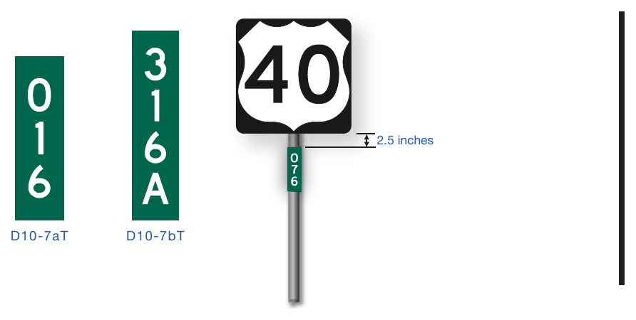
| Texas Reference Marker | D10-7aT | 2H.11A | 3 x 10 | 3 x 10 |
| Texas Reference Marker | D10-7bT | 2H.11A | 3 x 12 | 3 x 12 |
| Traffic Signal Speed | I1-1 | 2H.04 | 24 x 36 | — |
| Jurisdictional Boundary | I2-1 | 2H.05 | Varies x 18** Varies x 24 (O) | Varies x 36** Varies x 42 (O) |
| City Limit | I2-1T | 2H.05 | Varies x 24 | Varies x 24 |
| Geographical Feature | I2-2 | 2H.06 | Varies x 18** Varies x 24 (O) | Varies x 36** |
| Grade Separation Identification | I2-3 | 2H.10 | — | Varies x 18 |
| Grade Separation Identification (2 lines) | I2-3a | 2H.10 | — | Varies x 24 |
| Future Interstate Corridor | I2-4 | 2H.08 | 54 x 36 | 72 x 48 |
| Future I-XX Corridor | I2-4a | 2H.08 | 48 x 36 | 66 x 48 |
| Project Information | I2-5 | 2H.09 | 96 x 48 | 156 x 72 |
| Airport | I3-5 | 2H.01 | 24 x 24 | 30 x 30 |
| Bus Station | I3-6 | 2H.01 | 24 x 24 | 30 x 30 |
| Train Station | I3-7 | 2H.01 | 24 x 24 | 30 x 30 |
| Light Rail Transit Station | I3-8 | 2H.01 | 24 x 24 | — |
| Vehicle Ferry Terminal | I3-9 | 2H.01 | 24 x 24 | 30 x 30 |
| Passenger Only Ferry Terminal | I3-10 | 2H.01 | 24 x 24 | 30 x 30 |
| Ferry (plaque) | I3-10P | 2H.01 | 24 x 12 | 30 x 18 |
| Library | I4-1 | 2H.01 | 24 x 24 | — |
| Recycling Center | I4-2 | 2H.01 | 30 x 36 | — |
| Acknowledgment | I20-1 | 2H.13 | 36 x 30* | 72 x 48* |
* The size shown is the maximum size for the corresponding roadway classification. The size of the sign and acknowledgment logo should be appropriately reduced where shorter legends are used.
** The size shown is for the typical sign illustrated in the figure. The size should be determined based on the number of lines of legend on the sign.
*** Limitations on the size of Acknowledgment plaques are provided in Section 2H.13.
Notes: 1. Larger signs may be used when appropriate, except for the I20 series signs and plaque 2. (O) denotes Oversized 3. Dimensions are in inches shown as width x height
Table 2H-1. General Information Sign and Plaque Sizes
| Sign | Sign Designation | Section | Conventional Road | Freeway or Expressway |
|---|---|---|---|---|
| Acknowledgment | I20-2 | 2H.13 | 36 x 30* | 72 x 48* |
| Acknowledgment - Rest Area | I20-4 | 2H.13 | 56 x 36* | 72 x 48* |
| Acknowledgment - Welcome Center | I20-4a | 2H.13 | 56 x 36* | 72 x 48* |
| Acknowledgment (plaque) | I20-5P | 2H.13 | Varies x Varies*** | Varies x Varies*** |
| Adopt A Highway | I20-6T | 2H.13 | 48 x 48 | 48 x 48 |
| Last In Corridor (plaque) | W16-19P | 2H.14 | 24 x 18 | 24 x 18 |
* The size shown is the maximum size for the corresponding roadway classification. The size of the sign and acknowledgment logo should be appropriately reduced where shorter legends are used.
** The size shown is for the typical sign illustrated in the figure. The size should be determined based on the number of lines of legend on the sign.
*** Limitations on the size of Acknowledgment plaques are provided in Section 2H.13.
Notes: 1. Larger signs may be used when appropriate, except for the I20 series signs and plaque 2. (O) denotes Oversized 3. Dimensions are in inches shown as width x height
§2H.03 Airport Signs¶
Option
01. Guide signs for commercial service airports and general aviation airports may be provided from the nearest Interstate, other freeway, or conventional highway intersection directly to the airport, normally not to exceed 10 miles. The Airport (I3-5) symbol sign (see Figure 2H-1) along with a supplemental plaque may be used to indicate the specific name of the airport. An Airport symbol sign, with or without a supplemental name plaque or the word AIRPORT, and an arrow may be used as a trailblazer. (See FHWA Known Errors 01/24/2025)
Standard
02. Airport pictographs or other graphical representation of the specific airport shall not be used with or in place of the specific airport name on guide signs.
Support
03. Additional criteria for airport signing is contained in the Traffic Generator Table (see Table 2M-1A).
Guidance
04. If airport guide signs are used for international airports, adequate trailblazer signs should be used to provide motorist direction to the airport.
Support
05. Location and placement of all airport guide signs depends upon the availability of longitudinal spacing on highways.
06. Figure 2D-39 shows an example of the guide signing that is typically used for a large commercial airport.
§2H.04 Traffic Signal Speed Sign (I1-1)¶
Option
01. The Traffic Signal Speed (I1-1) sign (see Figure 2H-1) displaying the legend SIGNALS SET FOR XX MPH may be used to indicate a section of street or highway on which the traffic control signals are coordinated into a progressive system timed for a specified speed at all hours during which they are operated in a coordinated mode.
02. If different system progression speeds are set for different times of the day, a changeable message element may be used for the numerals of the Traffic Signal Speed sign. If the system is operated in coordinated mode only during certain times, a blank-out version of the Traffic Signal Speed sign may be used to display the entire message only during those times.
Standard
03. An electronic-display changeable section of the Traffic Signal Speed sign shall be a white legend on a black opaque or green background.
Guidance
04. If used, the Traffic Signal Speed sign should be mounted as near as practical to each intersection where the timed speed changes, and at intervals of several blocks throughout any section where the timed speed remains constant.
§2H.05 Jurisdictional Boundary Signs and City Limit Signs (I2-1 and I2-1T)¶
Option
01. The Jurisdictional Boundary (I2-1) sign may be used to mark the location of the jurisdictional boundary of a State, county, or municipality or the limits of an unincorporated municipal-level community, Tribal Nation, or governmental district where legal jurisdiction, road maintenance responsibility, or emergency response obligation changes.
Guidance
02. If used, the Jurisdictional Boundary sign should be located at or as near as practicable to the jurisdictional boundary without interfering with higher-priority traffic control devices. Notices of statutes or local ordinances should be located separately using regulatory signs (see Chapter 2B).
03. If used for an unincorporated community, the community should be one that is readily identifiable on official maps and be consistent with postal mailing addresses.
Standard
04. In accordance with Section 2H.01, the Jurisdictional Boundary sign shall be rectangular in shape and shall have a white legend on a green background. The sign shall display only the name of the State, county, municipality, Tribal Nation, or other identifiable community, and an appropriate legend such as ENTERING, STATE LINE, County, or the municipal classification.
05. Names of elected officials or promotional messages, such as notable accomplishments or claims, shall not be displayed on a Jurisdictional Boundary sign or added as a supplemental sign or plaque.
Option
06. A pictograph representing the jurisdiction may be displayed on the Jurisdictional Boundary sign.
Guidance
07. If the City Limit sign (see Figure 2H-1) is used on freeways and expressways, it should not include the population.
Option
08. If the City Limit sign is used on conventional roads, it may include the population.
Standard
If a pictograph is displayed on the Jurisdictional Boundary sign, it shall be the official seal of the jurisdiction and shall comply with the provisions of Section 2A.04. The pictograph shall be placed to the left of the legend. The height of the pictograph shall not exceed 2 times the height of the initial upper-case letter of the principal legend.
Guidance
11. Except where required by law, signs should not be used to identify the boundaries of special-purpose governmental districts, such as school districts, as such signs are generally promotional in nature and do not provide navigational or orientation assistance in conjunction with official maps that are available to the general public.
Support
Section 2H.07 contains information on State Welcome signs.
§2H.06 Geographical Feature Signs (I2-2)¶
Option
01. The Geographical Feature (I2-2) sign may be used to mark the locations of land features such as river or stream crossings, and summits, that are identifiable on maps or serve as landmarks in providing navigational orientation or reference to the road user.
Guidance
02. If used, the Geographical Feature sign should display only the name of the geographical feature. Additional information that is unnecessary for navigational or orientation purposes, such as watershed or tributary names, should not be displayed on the sign.
§2H.07 State Welcome Signs¶
Support
01. The design, placement, and function of State Welcome signs that are used to identify State lines differ from Jurisdictional Boundary (I2-1) signs (see Section 2H.05). Because of these differences, it is necessary to distinguish State Welcome signs from State line Jurisdictional Boundary signs.
Option
02. A State Welcome sign may be located at or in the vicinity of the State boundary except as prohibited in Paragraph 4 of this Section.
03. State Welcome signs may display the State seal or the State flag, the officially-adopted State motto or slogan, and the name of the Governor, in addition to the State name. State Welcome signs may use legend and background colors that provide adequate visual contrast rather than the standard sign colors.
Standard
04. State Welcome signs shall be located separate from other signs where they will not interfere with or detract from other traffic control devices.
05. State Welcome signs shall not display changeable or other electronic-display messages (see Chapter 2L). State Welcome signs shall not display messages that emulate promotional advertising of any type. State Welcome signs shall not incorporate Acknowledgment signs or messages (see Section 2H.13), or business identification sign panels or logos (see Section 2J.03) into their legends or assemblies. In accordance with Section 2A.04 of this Manual, telephone numbers, Internet addresses, and e-mail addresses, including domain names and uniform resource locators (URLs), and scanning graphics for the purpose of obtaining information shall not be displayed in the legends of State Welcome signs or on their supports.
Guidance
06. State Welcome signs should be located farther from the edge of the roadway than other traffic control devices.
07. The maximum size of a State Welcome sign should be consistent with the prevailing size of other guide signs based on the roadway type.
§2H.08 Future Interstate Corridor Signs (I2-4 and I2-4a)¶
Option
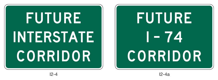
01. The Future Interstate Corridor (I2-4 and I2-4a) signs (see Figure 2H-2) may be used sparingly along an existing route that will be reconstructed as an Interstate route or along an existing route adjacent to a corridor through which an Interstate route will be constructed, in accordance with the Policy and Conditions stated in 23 CFR 470, Appendix C.
02. Where the route number has been approved by the FHWA, either the I2-4 or I2-4a sign may be used.
Standard
03. The I2-4a sign shall not be used where the route number has not been approved by the FHWA.
04. Future Interstate Corridor signs shall not be located where they could interfere with or detract from other traffic control devices. If used, Future Interstate Corridor signs shall be installed as independent, post-mounted sign assemblies.
05. Future Interstate Corridor signs shall not imply that an existing route has already been designated and marked as an Interstate route. Signs indicating that an existing route is designated as a future Interstate route or corridor shall not provide directional or distance information. Route Sign assemblies (see Section 2D.29) of any type shall not be used to sign a route as a future Interstate or other route. The Interstate route marker, or likeness thereof, shall not be displayed on the Future Interstate Corridor signs. (Due to a publication error in some versions of the CFR, please see the final rule at 88 Fed, Reg.87672 (Dec.19.2023) for revisions to 23 C.F.R. Part 470 Subpart A, Appendix C regarding signage for Future Interstate Corridors.)
Guidance
06. Future Interstate Corridor signs should be limited to strategic locations, such as at the beginning of the designated route or corridor, or beyond interchanges connecting from existing Interstate highways.
§2H.09 Project Information Sign (I2-5)¶
Support
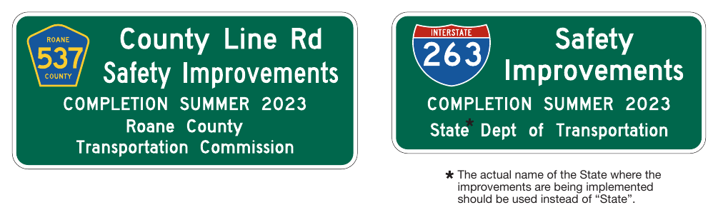
01. The Project Information (I2-5) sign (see Figure 2H-3) provides limited information to road users about a highway construction project on which work is imminently forthcoming or ongoing.
Standard
02. The Project Information sign legend shall be limited to the following project information:
- A. The roadway name or route number,
- B. A brief description or title of the project,
- C. The completion date expressed in either a month or season (Spring, Summer, Fall, or Winter), and
- D. The agency name.
Option
03. Project Information signs installed more than one week prior to commencement of work may include a start date.
Standard
04. Project Information signs shall not be installed more than one month prior to the commencement of work. When installing Project Information signs prior to the commencement of work, the jurisdiction shall have a policy on when the Project Information signs are to be installed. Project Information signs shall be removed at the conclusion of work on the project, even if the final inspection or project closeout has not yet occurred.
05. The number of Project Information signs shall be limited to one per direction of travel on the roadway on which the project is based. The location of the Project Information sign shall not interfere with the temporary traffic control zone devices.
06. The Project Information sign shall have a white legend on a green background and shall not display Internet addresses, e-mail addresses, or telephone numbers (see Section 2A.04).
§2H.10 Grade-Separated Roadway Identification Signs (I2-3 and I2-3a)¶
Option
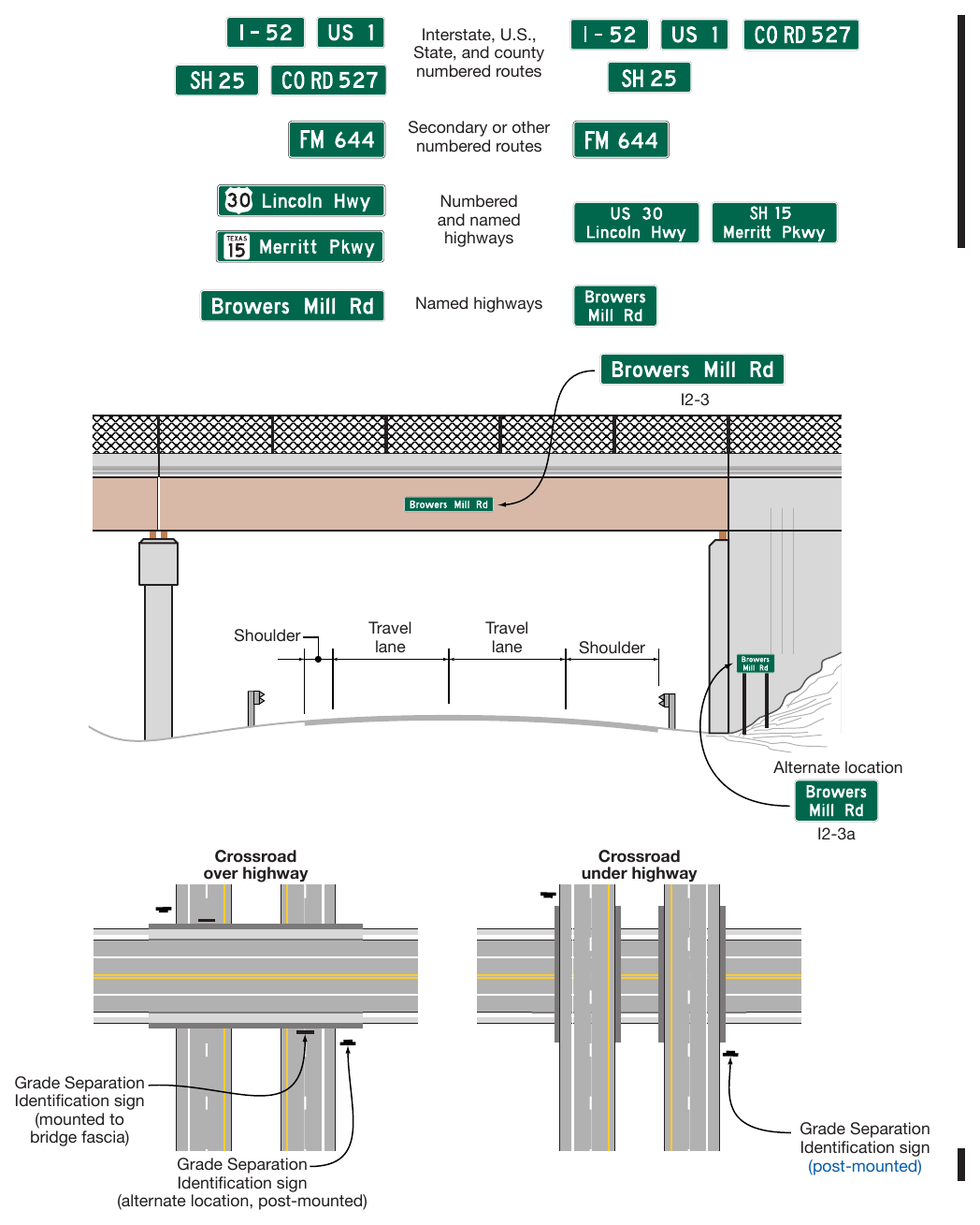
01. The Grade-Separated Roadway Identification (I2-3 and I2-3a) signs (see Figure 2H-4) may be used to identify a grade separation of another highway or other transportation facility such as a railway, bikeway, or pathway.
Guidance
02. Except as provided in Paragraph 4 of this Section, when used to identify an overcrossing structure, the I2-3 sign should be mounted above the travel lanes or shoulder of the highway below.
03. When used to identify an undercrossing structure, the I2-3 or I2-3a sign should be post-mounted in advance of the structure as near to it as practicable.
Option
04. When used to identify an overcrossing structure, the I2-3 or I2-3a sign may be post-mounted in front of an overcrossing or may be mounted to the abutment of the overcrossing facing approaching traffic.
§2H.11 Reference Location Signs (D10-1 through D10-3) and Intermediate Reference Location Signs (D10-1a through D10-3a)¶
Support
01. There are two types of reference location signs:
- A. Reference Location (D10-1 through D10-3) signs (see Figure 2H-5) show an integer distance point along a highway, and
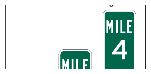
- B. Intermediate Reference Location (D10-1a through D10-3a) signs (see Figure 2H-6) show the same information as Reference Location signs, but they also show a tenth-of-a-mile decimal so that they can be installed between integer distance points along a highway.
Standard
02. Except when Enhanced Reference Location signs (see Section 2H.12) are used instead, Reference Location (D10-1 through D10-3) signs shall be placed on all expressway facilities that are located on a route where there is reference location sign continuity and on all freeway facilities to assist road users in estimating their progress, to provide a means for identifying the location of emergency incidents and traffic crashes, and to aid in highway maintenance and servicing.
Option
03. Reference Location (D10-1 through D10-3) signs may be installed along any section of a highway route or ramp to assist road users in estimating their progress, to provide a means for identifying the location of emergency incidents and traffic crashes, and to aid in highway maintenance and servicing.
04. To augment the Reference Location sign system, Intermediate Reference Location (D10-1a through D10-3a) signs, which show the tenth of a mile with a decimal point, may be installed at one tenth of a mile, two tenths of a mile, or one-half mile intervals.
Standard
05. When Intermediate Reference Location (D10-1a through D10-3a) signs are used to augment the reference location sign system, the reference location sign at the integer mile point shall display a decimal point and a zero numeral.
06. Reference Location and Intermediate Reference Location signs shall have a minimum mounting height of 4 feet, measured vertically from the bottom of the sign to the elevation of the near edge of the roadway, and shall not be governed by the mounting height requirements prescribed in Section 2A.15.
07. The distance numbering shall be continuous for each route within a State, except where overlaps occur (see Section 2E.22). Where routes overlap, reference location sign continuity shall be established for only one of the routes. If one of the overlapping routes is an Interstate route, that route shall be selected for continuity of distance numbering.
08. The route selected for continuity of distance numbering shall also have continuity in interchange exit numbering (see Section 2E.22).
Guidance
09. On a route without continuity of distance numbering, the first reference location sign beyond the overlap should indicate the total distance traveled on the route (including on the portion that did not have continuity of distance numbering) so that road users will have a means of correlating their travel distance between reference location signs with that shown on their odometer.
Standard
10. For divided highways, the distance measurement shall be made on the northbound and eastbound roadways. The reference location signs for southbound or westbound roadways shall be set at locations directly opposite the reference location signs for the northbound or eastbound roadways.
11. Zero distance shall begin at the south and west State lines, or at the south and west terminus points where routes begin within a State.
12. Except as provided in Paragraph 13 of this Section, reference location signs shall be installed on the right-hand side of the roadway.
Option
13. Where conditions limit or restrict the use of reference location signs on the right-hand side of the roadway, they may be installed in the median. On two-lane conventional roadways, reference location signs may be installed on one side of the roadway only and may be installed back-to-back. Reference location signs may be placed up to 30 feet from the edge of the pavement.
14. If a reference location sign cannot be installed in the correct location, it may be moved in either direction as much as 50 feet.
Guidance
15. If a reference location sign cannot be placed within 50 feet of the correct location, it should be omitted.
§2H.11A Texas Reference Marker System¶
Support
01. The Texas Reference Marker assembly (see Figure 2H-6A) provides the tie in the field to the Texas Reference Marker System. These sign installations are provided primarily for TxDOT’s use in referencing locations on a highway. The assemblies consist of a route sign and a reference marker.
Option
02. A cardinal direction auxiliary sign may be omitted on the Texas Reference Marker assembly.
Guidance
03. The reference marker assemblies should be placed every 2 miles on alternating sides of undivided conventional roadways and both sides of divided highways. The reference marker assemblies should not serve as confirmation or reassurance assemblies although they may if their location allows it to be used as such. The reference marker assemblies should not be moved or relocated after installation.
§2H.12 Enhanced Reference Location Signs (D10-4) and Intermediate Enhanced Reference Location Signs (D10-5)¶
Support
01. There are two types of enhanced reference location signs:
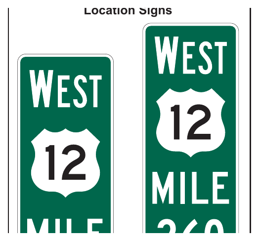
- A. Enhanced Reference Location (D10-4) signs (see Figure 2H-7), and
- B. Intermediate Enhanced Reference Location (D10-5) signs (see Figure 2H-7).
Option
02. An Enhanced Reference Location (D10-4) sign, which enhances the reference location sign system by identifying the route, may be placed on freeways or expressways (instead of reference location signs) or on conventional roads.
03. To augment an enhanced reference location sign system, an Intermediate Enhanced Reference Location (D10-5) sign, which shows the tenth of a mile with a decimal point, may be installed along any section of a highway route or ramp at one tenth of a mile, two tenths of a mile, or one-half mile intervals.
Standard
04. When an Intermediate Enhanced Reference Location (D10-5) sign is used to augment the reference location sign system, the Enhanced Reference Location sign at the integer mile point shall display a decimal point and a zero numeral.
05. Except as provided in Paragraph 6 of this Section, if enhanced reference location signs are used, they shall be vertical signs having a green background with a white legend and border, except for the route shield, which shall be the standard color and shape. The top line shall display the cardinal direction for the roadway. The second line shall display the applicable route shield for the roadway. The third line shall identify the mile reference for the location and the bottom line of the Intermediate Enhanced Reference Location sign shall give the tenth of a mile reference for the location preceded by a decimal point. (See FHWA Known Errors 01/24/2025)
Support
06. The provisions in Section 2H.11 regarding mounting height, distance numbering and measurements, sign continuity, and placement with respect to the right-hand shoulder and/or median for reference location signs also apply to enhanced reference location signs.
§2H.13 Acknowledgment Signs and Plaques (I20 Series)¶
Support
01. Acknowledgment signs and plaques (see Figure 2H-8) are a way of recognizing a company, business, or volunteer group that provides a highway-related service. Acknowledgment signs include sponsorship signs for adopt-a-highway litter removal programs, maintenance of a parkway or interchange, and other highway maintenance or beautification sponsorship programs.
Guidance
02. A State or local highway agency that elects to have an acknowledgment program should develop a policy on Acknowledgment signs and plaques. The policy should require that eligible sponsoring organizations comply with State laws prohibiting discrimination based on race, religion, color, age, sex, national origin, and other applicable laws.
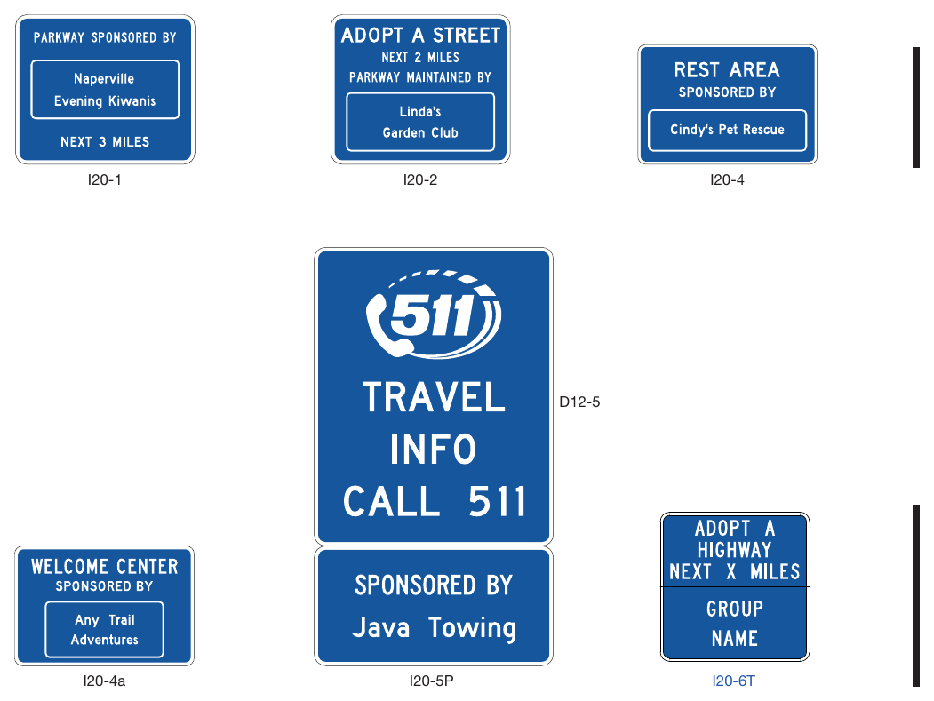
Signs shown: I20-1, I20-2, I20-4, D12-5, I20-4a, I20-5P, I20-6T
Standard
03. The State or local acknowledgment sign policy shall include all of the provisions regarding placement and design of Acknowledgment signs and plaques that are contained in this Section.
04. Because regulatory, warning, and guide signs have a higher priority, Acknowledgment signs shall only be installed where adequate spacing is available between the Acknowledgment sign and other higher priority signs. Acknowledgment signs shall not be installed in a position where they would obscure the road users’ view of other traffic control devices.
05. Acknowledgment signs shall not be installed at any of the following locations:
- A. On the front or back of, adjacent to, or around any other traffic control device, including traffic signs, highway traffic signals, and changeable message signs;
- B. On the front or back of, adjacent to, or around the supports or structures of other traffic control devices, or bridge piers; or
- C. At key decision points where a road user’s attention is more appropriately focused on other traffic control devices, roadway geometry, or traffic conditions, including exit and entrance ramps, merging or weaving areas, lane terminations, intersections, grade crossings, toll plazas, temporary traffic control zones, and areas of limited sight distance.
06. Acknowledgment signs and plaques shall have a white legend and border on a blue background. Acknowledgment signs shall be independent post-mounted roadside installations only and shall not be mounted overhead.
Option
07. An Acknowledgment sign may be used to acknowledge the sponsor of a rest area or welcome center.
Standard
08. Acknowledgment signs for a rest area, when located on the highway mainline, shall be limited to one sign per direction of travel from which the rest area is accessible, shall be located at least 500 feet from other traffic control devices, and shall not display names or representations of specific products or services provided by the sponsor within the rest area. Acknowledgment signs for rest areas shall display the legend REST AREA as the program activity, such as REST AREA SPONSORED BY. In accordance with Paragraph 5 of this Section, the Rest Area and Welcome Center Acknowledgment (I20-4 and I20-4a) signs shall not be combined in the same sign assembly with or substitute for the Rest Area General Service guide signs (see Section 2I.05).
Option
09. An additional Acknowledgment sign may be used within the rest area provided that it is not visible from the highway mainline or ramps to and from the rest area.
10. If a State has officially adopted and is actively promoting a program to encourage the use of safety rest areas through the use of a program name, then that program name may be displayed in smaller lettering below the legend REST AREA on the Rest Area Acknowledgment sign.
Standard
11. Program names or slogans, as described in Paragraph 14 of this Section, shall not be displayed on the Rest Area General Service guide signs or other types of traffic signs.
Guidance
12. The minimum spacing between Acknowledgment signs and any other traffic control signs, except parking regulation signs, should be:
- A. 150 feet on roadways with speed limits of less than 30 mph,
- B. 200 feet on roadways with speed limits of 30 to 45 mph, and
- C. 500 feet on roadways with speed limits greater than 45 mph.
13. If the placement of a newly-installed higher-priority traffic control device, such as a higher-priority sign, a highway traffic signal, or a temporary traffic control device, conflicts with an existing Acknowledgment sign, the Acknowledgment sign should be relocated, covered, or removed.
Option
14. State or local highway agencies may use their own pictograph (see definition in Section 1C.02) and/or a brief jurisdiction-wide program name, such as “Adopt-A-Highway” or “Litter Removal,” as part of any portion of the Acknowledgment sign, provided that the signs comply with the provisions for shape, sign and legend size, color, and lettering style in this Chapter and in Chapter 2A.
Guidance
15. Acknowledgment signs should clearly indicate the type of highway services provided by the sponsor.
Standard
16. In addition to the general provisions for signs described in Chapter 2A and the sign design principles covered in the “Standard Highway Sign Designs for Texas” publication (see Section 1A.05), Acknowledgment sign and plaque designs developed by State or local highway agencies shall comply with the following provisions:
- A. Neither the sign or plaque design nor the sponsor acknowledgment name or logo shall contain any contact information, directions, slogans (other than a brief jurisdiction-wide program name, if used), telephone numbers, e-mail or Internet addresses, including domain names and uniform resource locators (URLs), metadata tags (“hash-tags”), or quick-response (QR) codes, bar codes, or similar scanning graphics (see Section 2A.04);
- B. Except for the sponsor acknowledgment logo or program name, all of the lettering shall be in upper-case letters of the Standard Alphabets as provided in the “Standard Highway Sign Designs for Texas” publication (see Section 1A.05);
- C. If a logo, instead of a word legend, is used to represent the sponsor, the logo shall be the primary logo that identifies the sponsoring entity. Secondary or alternate logos, slogans, products, mascots, spokespersons, or other items associated with the sponsoring entity’s commercial advertising or marketing shall not be displayed on Acknowledgment signs or plaques;
- D. In order to keep the main focus on the highway-related service and not on the sponsor acknowledgment name or logo, the area reserved for the sponsor acknowledgment name or logo shall not be located at the top of the sign or plaque, shall be a maximum of 8 square feet in area, and shall not exceed ⅓ of the total area of the sign;
- E. The entire sign display area of an Acknowledgment sign assembly shall not exceed 24 square feet;
- F. The sign or plaque shall not contain any messages, lights, symbols, or logos that resemble any official traffic control devices;
- G. The sign or plaque shall not contain any external or internal illumination, light-emitting diodes, luminous tubing, fiber optics, luminescent panels, or other flashing, moving, or animated features;
- H. The sign or plaque shall not distract from official traffic control messages such as regulatory, warning, or guidance messages;
- I. The area of the plaque shall not exceed the lesser of ⅓ the area of the General Service sign below which it is mounted or 24 square feet;
- J. The plaque size shall be based on the standard sizes as specified in Table 2H-1. If the size of the General Service sign is oversized for its application (greater than the size specified for the corresponding roadway application in Table 2H-1), or if the size of the General Service sign increases due to modification of the sign legend, a corresponding increase in the size of the plaque shall not be allowed; and
- K. The sign or plaque shall not display promotional or contact information about the agency’s sponsorship program, including if the sign or plaque does not currently display a sponsor.
Option
17. If a specific outlet of a business with multiple locations in the same area is the sponsoring entity, such as a franchisee, the area reserved for the sponsor acknowledgment name or logo may include the name of the municipality or neighborhood in which the sponsoring entity is located.
18. An Acknowledgment plaque may be mounted below the following General Service signs to acknowledge the sponsor of a corridor-based or region-based highway-related service:
- A. Radio-Weather Information (D12-1) sign (see Section 2I.09);
- B. Radio-Traffic Information (D12-1a) sign (see Section 2I.09);
- C. TRAVEL INFO CALL 511 (D12-5 and D12-5a) signs (see Section 2I.12); and
- D. Roadside Assistance (D12-6) sign (see Section 2I.13).
Standard
19. An Acknowledgment plaque shall not be mounted in conjunction with any other sign or traffic control device. An Acknowledgment plaque shall not be used alone or without one of the General Service signs specified in Paragraph 18 of this Section.
20. The general restrictions on the type of content allowed for display on Acknowledgment signs (see Paragraph 16 of this Section) shall apply to the legends of Acknowledgment plaques.
§2H.14 Alternative Fuels Corridor Sign (D9-19)¶
Option
01. The Alternative Fuels Corridor (D9-19) sign (see Figure 2H-9) may be used to inform motorists of an alternative fuels corridor highway segment that has been designated by the Secretary of Transportation as “Corridor Ready.”
Standard
02. Alternative Fuels Corridor signs shall only be used to designate alternative fuels corridor highway segments that have been designated by the Federal Highway Administration as “Corridor Ready.” The appropriate General Service signs or plaques identifying the alternative fuels available in the corridor shall be included with the Alternative Fuels Corridor sign in a sign assembly. The alternative fuel services for an alternative fuels corridor shall be limited to electric vehicle charging, compressed natural gas, liquid natural gas, liquified petroleum, and hydrogen.
Support
03. The General Service (D9-11a, D9-11b, D9-11d, D9-11e, and D9-11f) symbol signs for use with an Alternative Fuels Corridor sign are shown in Figure 2I-1.
Standard
04. Alternative Fuels Corridor signs shall only be post-mounted on the side of the road and shall not be mounted overhead.
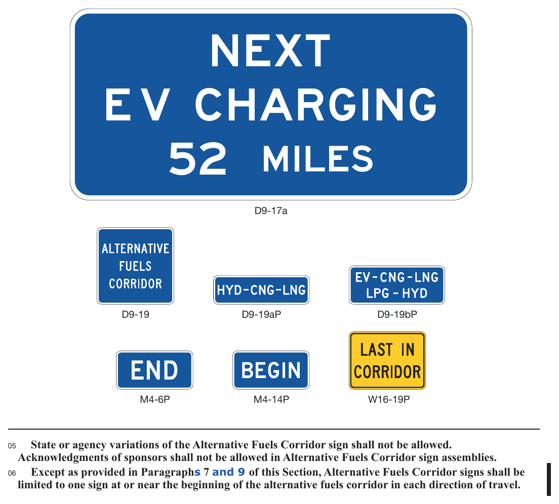
Signs shown: D9-17a, D9-19, D9-19aP, D9-19bP, M4-6P, M4-14P, W16-19P
05. State or agency variations of the Alternative Fuels Corridor sign shall not be allowed. Acknowledgments of sponsors shall not be allowed in Alternative Fuels Corridor sign assemblies.
06. Except as provided in Paragraphs 7 and 9 of this Section, Alternative Fuels Corridor signs shall be limited to one sign at or near the beginning of the alternative fuels corridor in each direction of travel.
Option
07. For long corridors, such as segments connecting control cities or major urban areas, additional signs may be located beyond major intersections or major interchanges following the typical post-interchange sign sequence.
08. The beginning of an alternative fuels corridor may be indicated with a BEGIN (M4-14P) plaque (see Figure 2H-9) with a white legend and border on a blue background mounted above the Alternative Fuels Corridor sign in the sign assembly. (See FHWA Known Errors 01/24/2025)
09. The end of an alternative fuels corridor may be indicated with an END (M4-6P) plaque (see Figure 2H-9) with a white legend and border on a blue background mounted above the Alternative Fuels Corridor sign in the sign assembly.
Standard
10. The General Service signs shall not be used in the sign assembly indicating the end of a corridor.
11. When the availability of one or more of the alternative fuel facilities discontinues in an alternative fuels corridor, the LAST IN CORRIDOR (W16-19P) plaque (see Figure 2H-9) shall be included on the last General Service directional assembly on the approach to the interchange or intersection.
Option
12. When the availability of one or more of the alternative fuel facilities discontinues in an alternative fuels corridor, an Alternative Fuels Corridor sign with accompanying General Service signs indicating the types of fuels still available in the corridor may be provided beyond the intersection or interchange where the last discontinued fuel facilities were available.
13. When the distance between electric vehicle (EV) charging services in an alternative fuels corridor is greater than 50 miles, the Next EV Charging (D9-17a) sign (see Figure 2H-9) may be located after the EV charging directional assembly, but before the EV charging service exit or turn, to inform road users of the extended distance to the next EV charging service.
Standard
14. The Alternative Fuels Corridor (D9-19) sign shall not be used as a directional sign in a directional assembly, or be combined with other signs, except as provided in this Section.
Option
15. Up to three General Service symbol signs arranged horizontally displaying the alternative fuels available in the designated corridor may be installed below the Alternative Fuels Corridor sign (see Figure 2H-10).
Standard
16. The size of the General Service symbol signs for the alternative fuels available shall not exceed 18 x 18 inches when mounted with the 24 x 24-inch Alternative Fuels Corridor sign and 24 x 24 inches when mounted with the 36 x 36-inch Alternative Fuels Corridor sign.
Guidance
17. When the number of eligible alternative fuels available in the corridor exceeds three, a separate plaque with the two-letter or three-letter designations (D9-19aP or D9-19bP) of each of the fuels available (see Figure 2H-9) should be used in place of the General Service symbol signs.
Standard
18. When the Alternative Fuels Corridor sign is used in a designated corridor on a freeway or expressway, the applicable General Service signs shall be installed on the approach to an interchange in the corridor from which the designated fuel services are available. If the services are not visible from the ramp of a single-exit interchange, the service signing shall be repeated at the intersection of the exit ramp and the crossroad (see Figure 2H-10). Where the alternative fuel facility is not located along the crossroad, additional General Service directional assemblies shall be installed in advance of each subsequent turn to reach the facility (see Figure 2H-11).
Support
19. Because regulatory, warning, and guide signs are necessary for safe and efficient movement of traffic, they have a higher priority in placement location over Alternative Fuels Corridor signs.
Standard
20. Alternative Fuels Corridor sign assemblies shall be limited to those locations where adequate spacing is available between the Alternative Fuels Corridor sign and other signs. Alternative Fuels Corridor signs shall not be installed in a location where they might distract driver’s attention from other traffic control devices or the roadway in a complex roadway environment. If the placement of a newly-installed, higherpriority traffic control device conflicts with an existing Alternative Fuels Corridor sign, the Alternative Fuels Corridor sign shall be relocated, covered, or removed.
21. Alternative Fuels Corridor signs shall not be installed on routes other than those officially designated as alternative fuels corridors, even if to provide directional information to such corridors.
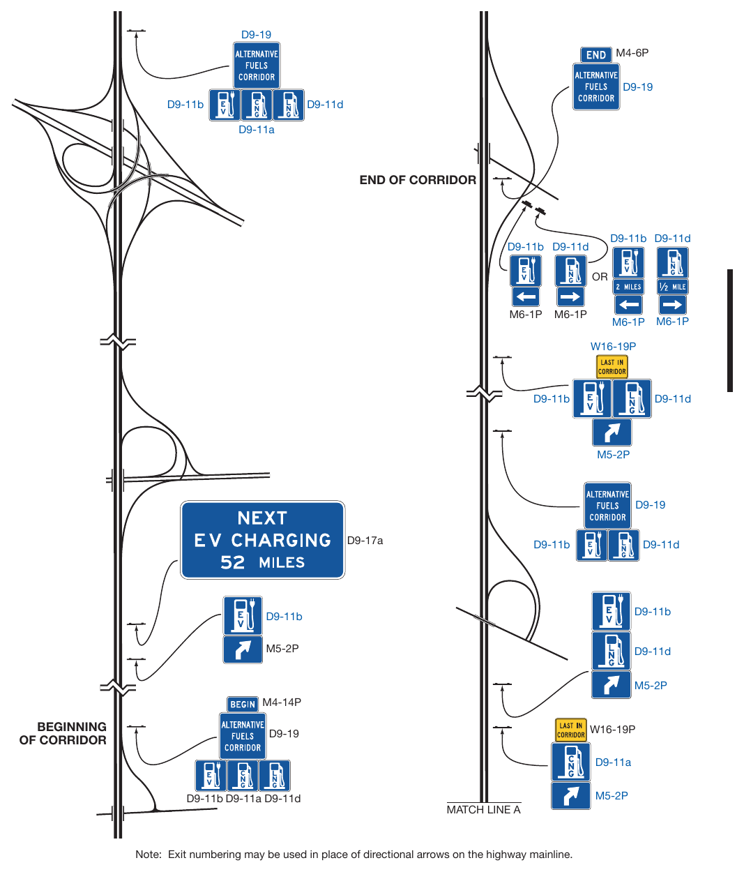
Signs shown: D9-19, M4-6P, D9-11b, D9-11d, D9-11a, M6-1P, W16-19P, M5-2P, D9-17a, M4-14P
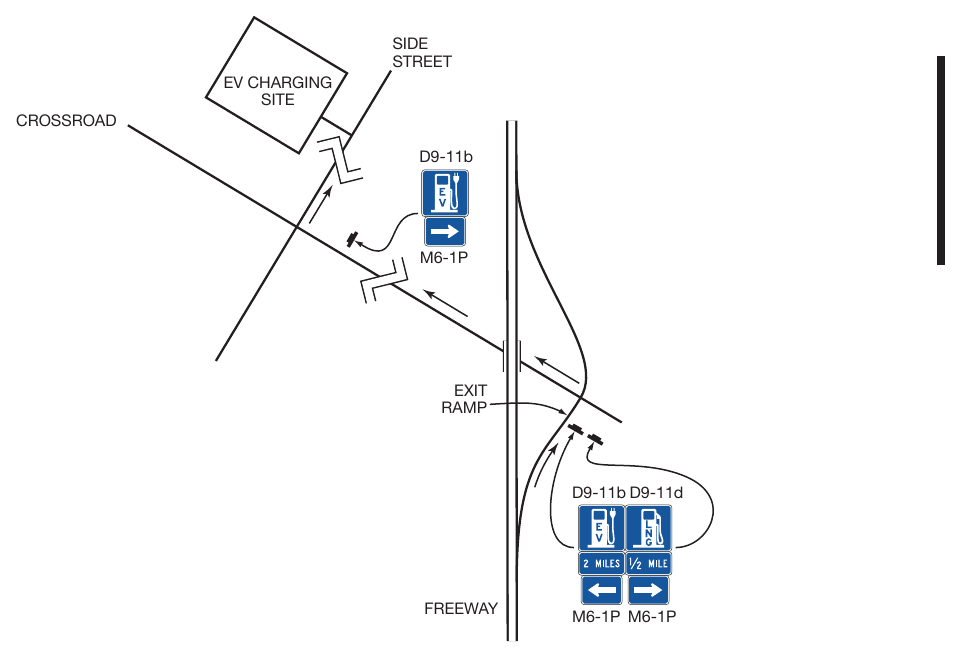
Chapter 2I. GENERAL SERVICE SIGNS¶
§2I.01 Sizes of General Service Signs¶
Standard
01. Except as provided in Section 2A.07, the sizes of General Service signs that have a standardized design shall be as shown in Table 2I-1.
Support
02. Section 2A.07 contains information regarding the applicability of the various columns in Table 2I-1.
Option
03. Signs larger than those shown in Table 2I-1 may be used (see Section 2A.07).
Table 2I-1. General Service Sign and Plaque Sizes (Sheet 1 of 2)
| Sign or Plaque | Sign Designation | Section | Conventional Road | Freeway or Expressway |
|---|---|---|---|---|
| Rest Area Advance | D5-1 | 2I.05 | — | 132 x 60 |
| Rest Area 1 Mile Accessible | D5-1T | 2I.05 | 36 x 36 | — |
| Rest Area Advance Direction | D5-1a | 2I.05 | — | 132 x 60 |
| Rest Area Entrance Direction | D5-2 | 2I.05 | — | 132 x 66 |
| Rest Area Gore | D5-2a | 2I.05 | 42 x 48* | 78 x 78 |
| Rest Area Directional Accessible | D5-5T | 2I.05 | 36 x 36 | — |
| Next Rest Area | D5-6 | 2I.05 | 78 x 54* | 132 x 78 |
| Next Rest Area (plaque) | D5-6PT | 2I.05 | — | 132 x 30* |
| Rest Area Tourist Info Center Advance | D5-7 | 2I.08 | 90 x 72* | 156 x 108* |
| Rest Area Texas Travel Info Center Advance | D5-7T | 2I.08 | 96 x 72 | 168 x 108 |
| Rest Area Tourist Info Center Advance Direction | D5-7a | 2I.08 | 90 x 72* | 156 x 108* |
| Rest Area Texas Travel Info Center Advance Direction | D5-7aT | 2I.08 | 96 x 72 | 168 x 108 |
| Rest Area Tourist Info Center Entrance Direction | D5-8 | 2I.08 | 84 x 72* | 138 x 108* |
| Rest Area Texas Travel Info Center Entrance Direction | D5-8T | 2I.08 | 96 x 72 | 168 x 108 |
| Parking Area Advance | D5-9 | 2I.05 | — | 162 x 60* |
| Parking Area 1 Mile | D5-9T | 2I.05 | 36 x 36 | — |
| Parking Area Entrance Direction | D5-9a | 2I.05 | — | 162 x 60* |
| Parking Area Gore | D5-9b | 2I.05 | — | 108 x 78* |
| Parking Area Directional | D5-9cT | 2I.05 | 36 x 36 | — |
| Picnic Area (Roadside Table, Roadside Park) Advance | D5-10 | 2I.05 | — | 144 x 60* |
| Picnic Area 1 Mile | D5-10T | 21.05 | 36 x 36 | — |
* The size shown is for a sign with a REST AREA, PARKING AREA, PICNIC AREA, SCENIC AREA, and/or TOURIST INFO CENTER legend. The size should be appropriately adjusted if an alternate legend is used.
** The size shown is for a sign with four lines of services. The size should be appropriately adjusted depending on the amount of legend displayed.
*** The "Standard Highway Sign Designs for Texas" publication contains layouts for the 18 x 18-inch and 24 x 24-inch alternative fuels symbol signs mounted with the Alternative Fuels Corridor sign, in accordance with Section 2H.14.
Notes: 1. Larger signs may be used when appropriate. 2. Dimensions in inches are shown as width x height 3. Where two sizes are shown, the larger size is for freeways (F) and the smaller size is for expressways (E)
Table 2I-1. General Service Sign and Plaque Sizes (Sheet 2 of 2)
| Sign or Plaque | Sign Designation | Section | Conventional Road | Freeway or Expressway |
|---|---|---|---|---|
| Picnic Area (Roadside Table, Roadside Park) Entrance Direction | D5-10a | 2I.05 | — | 144 x 60* |
| Picnic Area (Roadside Table, Roadside Park) Gore | D5-10b | 2I.05 | — | 84 x 78* |
| Picnic Area Directional | D5-10cT | 2I.05 | 36 x 36 | — |
| Scenic Area (Scenic View, Scenic Overlook) Advance | D5-11 | 2I.05 | — | 144 x 60* |
| Scenic Area 1 Mile | D5-11T | 2I.05 | 36 x 36 | — |
| Scenic Area (Scenic View, Scenic Overlook) Entrance Direction | D5-11a | 2I.05 | — | 144 x 60* |
| Scenic Area (Scenic View, Scenic Overlook) Gore | D5-11b | 2I.05 | — | 90 x 78* |
| Scenic Area Directional | D5-11cT | 2I.05 | 36 x 36 | — |
| Telephone | D9-1 | 2I.02 | 24 x 24 | 30 x 30 |
| Hospital | D9-2 | 2I.02 | 24 x 24 | 30 x 30 |
| Camping | D9-3 | 2I.02 | 24 x 24 | 30 x 30 |
| Litter Container | D9-4 | 2I.02 | 24 x 30 | 36 x 48 |
| International Symbol of Accessibility | D9-6 | 2I.02 | 24 x 24 | 30 x 30 |
| Van Accessible (plaque) | D9-6P | 2I.02 | 18 x 9 | — |
| Gas | D9-7 | 2I.02 | 24 x 24 | 30 x 30 |
| Food | D9-8 | 2I.02 | 24 x 24 | 30 x 30 |
| Lodging | D9-9 | 2I.02 | 24 x 24 | 30 x 30 |
| Tourist Information | D9-10 | 2I.02 | 24 x 24 | 30 x 30 |
| Diesel Fuel | D9-11 | 2I.02 | 24 x 24 | 30 x 30 |
| Alternative Fuel - Compressed Natural Gas | D9-11a | 2I.02 | 24 x 24*** | 30 x 30*** |
| Electric Vehicle Charging | D9-11b | 2I.02 | 24 x 24*** | 30 x 30*** |
| Electric Vehicle Charging (plaque) | D9-11bP | 2I.02 | 24 x 18 | 30 x 24 |
| Alternative Fuel - Ethanol | D9-11c | 2I.02 | 24 x 24 | 30 x 30 |
| Alternative Fuel - Liquefied Natural Gas | D9-11d | 2I.02 | 24 x 24*** | 30 x 30*** |
| Alternative Fuel - Liquefied Petroleum Gas | D9-11e | 2I.02 | 24 x 24*** | 30 x 30*** |
| Alternative Fuel - Hydrogen | D9-11f | 2I.02 | 24 x 24*** | 30 x 30*** |
| Alternative Fuel - Biofuel | D9-11g | 2I.02 | 24 x 24 | 30 x 30 |
| RV Sanitary Station | D9-12 | 2I.02 | 24 x 24 | 30 x 30 |
| Emergency Medical Services | D9-13 | 2I.02 | 24 x 24 | 30 x 30 |
| Hospital (plaque) | D9-13aP | 2I.02 | 24 x 12 | 30 x 12 |
| Emergency Medical Care (plaque) | D9-13cP | 2I.02 | 24 x 18 | 30 x 24 |
| Trauma Center (plaque) | D9-13dP | 2I.02 | 24 x 12 | 30 x 15 |
| Police | D9-14 | 2I.02 | 24 x 24 | 30 x 30 |
| Truck Parking | D9-16 | 2I.03 | 24 x 24 | 30 x 30 |
| Truck External Power (plaque) | D9-16aP | 2I.03 | 24 x 24 | 30 x 30 |
* The size shown is for a sign with a REST AREA, PARKING AREA, PICNIC AREA, SCENIC AREA, and/or TOURIST INFO CENTER legend. The size should be appropriately adjusted if an alternate legend is used.
** The size shown is for a sign with four lines of services. The size should be appropriately adjusted depending on the amount of legend displayed.
*** The "Standard Highway Sign Designs for Texas" publication contains layouts for the 18 x 18-inch and 24 x 24-inch alternative fuels symbol signs mounted with the Alternative Fuels Corridor sign, in accordance with Section 2H.14.
Notes: 1. Larger signs may be used when appropriate. 2. Dimensions in inches are shown as width x height 3. Where two sizes are shown, the larger size is for freeways (F) and the smaller size is for expressways (E)
Table 2I-1. General Service Sign and Plaque Sizes (Sheet 3 of 3)
| Sign or Plaque | Sign Designation | Section | Conventional Road | Freeway or Expressway |
|---|---|---|---|---|
| Truck Parking Availability - Exit Number | D9-16b | 2I.15 | Varies x 144 | Varies x 144 |
| Truck Parking Availability - Distance | D9-16c | 2I.15 | Varies x 144 | Varies x 144 |
| Truck Parking Availability - Rest Area | D9-16d | 2I.15 | Varies x Varies | Varies x Varies |
| Truck Parking Availability - Combined | D9-16e | 2I.15 | Varies x Varies | Varies x Varies |
| Next Services Advance (plaque) | D9-17P | 2I.02 | 72 x 24 | 114 x 30 |
| General Services with Exit Number | D9-18a | 2I.03 | 72 x 60 | 132 x 108** (F) 102 x 84** (E) |
| General Services (up to 6 symbols) with Action Message | D9-18b | 2I.03 | 108 x 84 | 132 x 114 (F) 132 x 108 (E) |
| General Services with Action Message | D9-18c | 2I.03 | 72 x 60** | 132 x 108** (F) 102 x 84** (E) |
| Rural Interchange General Services (up to 3 symbols) (plaque) | D9-18dP | 2I.03 | — | 120 x 36 |
| Rural Interchange General Services (1 line) (plaque) | D9-18eP | 2I.03 | — | Varies x 24 |
| Rural Interchange General Services (2 line) (plaque) | D9-18fP | 2I.03 | — | Varies x 42 |
| Pharmacy | D9-20 | 2I.02 | 24 x 24 | 30 x 30 |
| 24-Hour (plaque) | D9-20aP | 2I.02 | 24 x 12 | 30 x 12 |
| Telecommunications Device for the Deaf | D9-21 | 2I.02 | 24 x 24 | 30 x 30 |
| Wireless Internet | D9-22 | 2I.02 | 24 x 24 | 30 x 30 |
| Radio - Weather Information | D12-1 | 2I.09 | 84 x 48 | 132 x 84 |
| Radio - Traffic Information | D12-1a | 2I.09 | 96 x 48 | 120 x 60 |
| Urgent Message When Flashing (plaque) | D12-1bP | 2I.09 | 84 x 30 | 108 x 36 |
| Carpool Information | D12-2 | 2I.14 | 60 x 42 | 96 x 66 |
| Channel 9 Monitored | D12-3 | 2I.10 | 84 x 48 | 132 x 84 |
| Emergency Call 911 | D12-4 | 2I.11 | 66 x 30 | 96 x 48 |
| Travel Info Call 511 (pictograph) | D12-5 | 2I.12 | 48 x 60 | 66 x 72 |
| Travel Info Call 511 | D12-5a | 2I.12 | 48 x 36 | 66 x 48 |
| Roadside Assistance | D12-6 | 2I.13 | 60 x 42 | 78 x 54 |
* The size shown is for a sign with a REST AREA, PARKING AREA, PICNIC AREA, SCENIC AREA, and/or TOURIST INFO CENTER legend. The size should be appropriately adjusted if an alternate legend is used.
** The size shown is for a sign with four lines of services. The size should be appropriately adjusted depending on the amount of legend displayed.
*** The "Standard Highway Sign Designs for Texas" publication contains layouts for the 18 x 18-inch and 24 x 24-inch alternative fuels symbol signs mounted with the Alternative Fuels Corridor sign, in accordance with Section 2H.14.
Notes: 1. Larger signs may be used when appropriate. 2. Dimensions in inches are shown as width x height 3. Where two sizes are shown, the larger size is for freeways (F) and the smaller size is for expressways (E)
§2I.02 General Service Signs for Conventional Roads¶
Support
01. On conventional roads, commercial services such as gas, food, and lodging generally are within sight and are available to the road user at reasonably frequent intervals along the route. Consequently, on this class of road there usually is no need for special signs calling attention to these services. Moreover, General Service signing is usually not needed in urban areas except for hospitals, law enforcement assistance, tourist information centers, and camping.
Option
02. General Service signs (see Figure 2I-1) may be used on conventional roads where such services are infrequent and are found only on an intersecting highway or crossroad.
Standard
03. All General Service signs and supplemental sign panels shall have a white legend and border on a blue background.
Guidance
04. General Service signs should be installed at a suitable distance in advance of the turn-off point or intersecting highway.
Standard
05. To be eligible for an EV Charging General Service sign on a conventional road, the EV chargers provided shall meet the criteria for Direct Current Fast Chargers provided in 23 CFR 680.106 and be in continuous operation at least 16 hours per day, 7 days per week.
06. General Service signs, if used at intersections, shall be accompanied by a directional message.
Option
07. The Advance Turn (M5 series) or Directional Arrow (M6 series) auxiliary plaques (see Figure 2I-1) with white arrows on blue backgrounds may be used with General Service symbol signs to create a General Service directional assembly.
08. The General Service sign legends may be either symbols or word messages.
Standard
09. Symbols and word message General Service legends shall not be intermixed on the same sign.
10. The Pharmacy (D9-20) sign shall only be used to indicate the availability of a pharmacy that is open, with a State-licensed pharmacist present and on duty, 24 hours per day, 7 days per week, and that is located within 3 miles of an interchange on the Federal-aid system. The D9-20 sign shall have a 24 HR (D9-20aP) plaque mounted below it.
11. Use of the Hospital (D9-2) sign or the HOSPITAL (D9-13aP) plaque (see Figure 2I-1) shall be limited to general hospitals licensed under Chapter 241 of the Texas Health and Safety Code that operate 24 hours per day, 7 days per week.
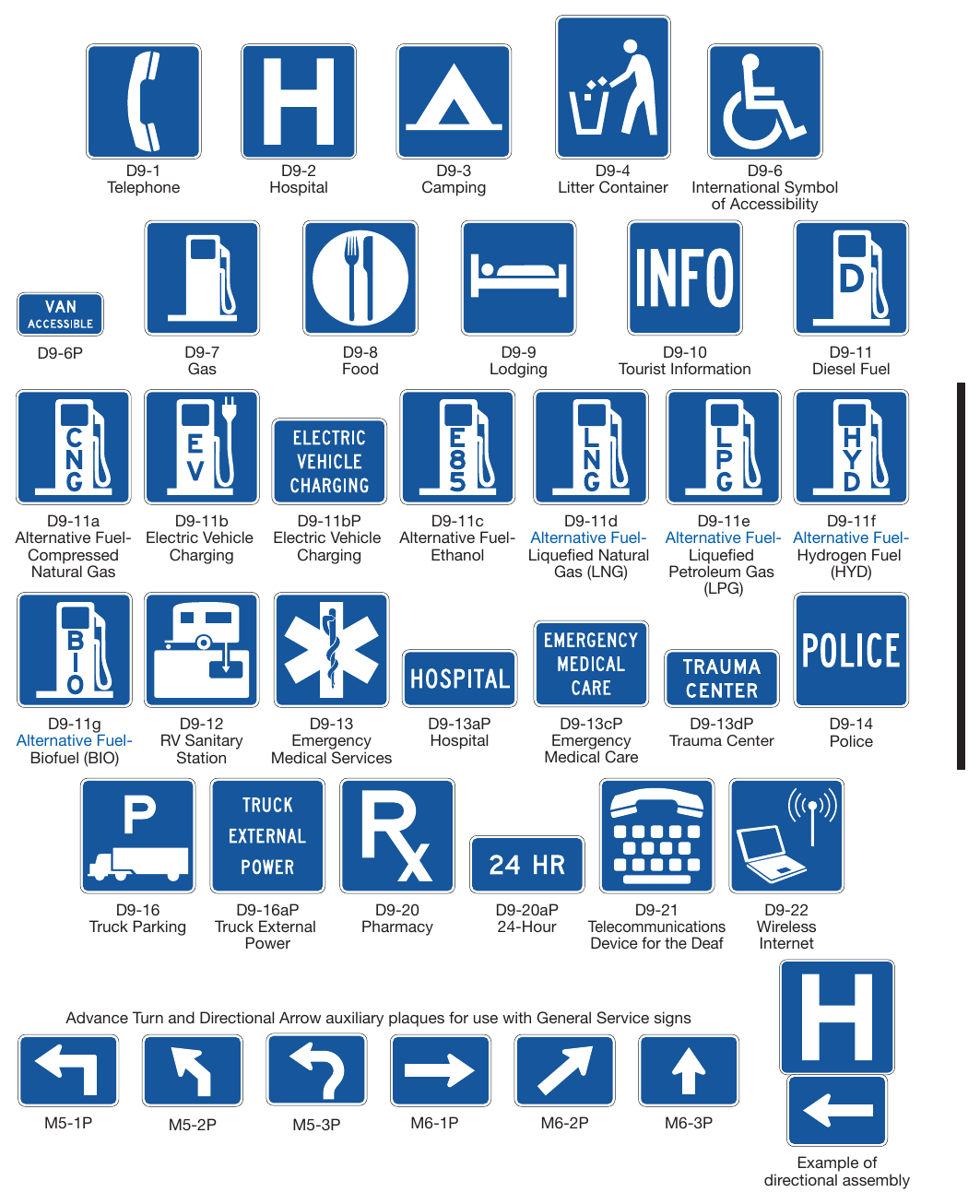
Signs shown: D9-1, D9-2, D9-3, D9-4, D9-6, D9-6P, D9-7, D9-8, D9-9, D9-10, D9-11, D9-11a, D9-11b, D9-11bP, D9-11c, D9-11d, D9-11e, D9-11f, D9-11g, D9-12, D9-13, D9-13aP, D9-13cP, D9-13dP, D9-14, D9-16, D9-16aP, D9-20, D9-20aP, D9-21, D9-22
Support
12. Formats for displaying different combinations of these services are described in Section 2I.03.
Option
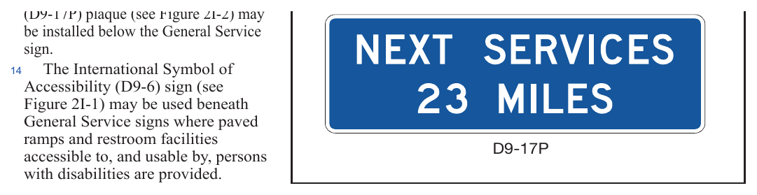
13. If the distance to the next point at which services are available is 10 miles or more, a Next Services Advance (D9-17P) plaque (see Figure 2I-2) may be installed below the General Service sign. Accessibility (D9-6) sign (see Figure 2I-1) may be used beneath General Service signs where paved ramps and restroom facilities accessible to, and usable by, persons with disabilities are provided.
Guidance
When the D9-6 sign is used in accordance with Paragraph 13 of this Section, and van-accessible parking is available at the facility, a VAN ACCESSIBLE (D9-6P) plaque (see Figure 2I-1) should be mounted below the D9-6 sign.
Option
16. The Recreational Vehicle Sanitary Station (D9-12) sign (see Figure 2I-1) may be used as needed to indicate the availability of facilities designed for the use of dumping wastes from recreational vehicle holding tanks.
17. The Litter Container (D9-4) sign (see Figure 2I-1) may be placed in advance of roadside turn-outs or rest areas, unless it distracts the driver’s attention from other more important regulatory, warning, or directional signs.
18. The Emergency Medical Services (D9-13) symbol sign (see Figure 2I-1) may be used to identify medical service facilities that have been included in the Emergency Medical Services system under a signing policy developed by the State and/or local highway agency.
Standard
19. The Emergency Medical Services symbol sign shall not be used to identify services other than general hospitals licensed under Chapter 241 of the Texas Health and Safety Code and freestanding emergency medical care facilities licensed under Chapter 254 of the Texas Health and Safety Code that operate 24 hours per day, 7 days per week. If used, the Emergency Medical Services symbol sign shall be supplemented by a sign or plaque, as provided in Paragraph 20 of this Section, identifying the type of service provided.
Option
20. The Emergency Medical Services symbol sign may be used above the HOSPITAL (D9-13aP) plaque or above a plaque with the legend EMERGENCY MEDICAL CARE (D9-13cP), or TRAUMA CENTER (D9-13dP). The Emergency Medical Services symbol sign may also be used to supplement Telephone (D9-1), Channel 9 Monitored (D12-3) (see Figure 2I-8), or POLICE (D9-14) signs.
Guidance
21. General Service Signs for hospitals and emergency medical care facilities should not include the name of the facility.
Standard
22. The legend EMERGENCY MEDICAL CARE shall not be used for services other than qualified freestanding emergency medical care facilities licensed under Chapter 254 of the Texas Health and Safety Code that operate 24 hours per day, 7 days per week.
§2I.03 General Service Signs for Freeways and Expressways¶
Support
01. General Service (D9-18 series) signs (see Figure 2I-3) are generally not appropriate at major interchanges (see definition in Section 2E.11) and in urban areas.
Guidance
02. General Service signs for gas, food, lodging, camping and 24-hour pharmacies should not be used on roadways eligible for Specific Service signs (see Specific Service Signs in Chapter 2J).
Standard
03. General Service signs shall have a white legend and border on a blue background. Letter and numeral sizes shall comply with the minimum requirements of Tables 2E-4A and 2E-5. All approved symbols shall be permitted as alternatives to word messages, but symbols and word service messages shall not be intermixed on the same sign. If the services are not visible from the ramp of a single-exit interchange, the service signing shall be repeated in smaller size at the intersection of the exit ramp and the crossroad. Such service signs shall use arrows to indicate the direction to the services.
04. The Hospital (D9-2) symbol sign shall not be used to identify services other than general hospitals licensed under Chapter 241 of the Texas Health and Safety Code.
Guidance
Where General Service signs are used along routes with exit numbering, the General Service sign should include the exit number within the sign face as shown in Figure 2I-3.
06. Distance to services should be displayed on General Service signs along the exit ramp where distances are more than 1 mile from the ramp intersection with the crossroad.
07. General Service signing should only be provided at locations where the road user can return to the freeway or expressway and continue in the same direction of travel. (See FHWA Known Errors 01/24/2025)
08. Only services that fulfill the needs of the road user should be displayed on General Service signs. If General
05. Service signs are used, the criteria for the availability of the various types of services to be displayed should be the same as the eligibility requirement for businesses participating in the specific service sign program (see Chapter 2J).
Standard
09. To be eligible for an EV Charging General Service sign on freeways and expressways, the EV chargers provided shall meet the criteria for Direct Current Fast Chargers provided in 23 CFR 680.106 and be in continuous operation at least 16 hours per day, 7 days per week.
Support
10. Motorist expectations for facilities providing alternative fuels, such as EV Charging, compressed natural gas, liquefied natural gas, liquefied petroleum gas, and hydrogen, vary considerably and alternative fuel vehicles might have different needs than conventional fuel vehicles.
Guidance
11. The policy criteria for alternative fuel vehicles should take into account the needs, convenience, and safety of alternative fuel vehicle users (see Section 2H.14).
Standard
12. For any service that is operated on a seasonal basis only, the General Service signs shall be removed or covered during periods when the service is not available.
13. The General Service signs shall be mounted in an effective location, between the Advance Guide sign and the Exit Direction sign, in advance of the exit leading to the available services.
Option
14. If the distance to the next point where services are available is greater than 10 miles, a Next Services Advance (D9-17P) plaque (see Figure 2I-2) may be installed below the Exit Direction sign.
Standard
15. Signs for services shall comply with the format for General Service signs (see Section 2I.02) and as provided in this Manual. No more than six general road user services shall be displayed on one sign, which includes any appended supplemental signs or plaques. General Service signs shall display the legends for one or more of the following services: Food, Gas, EV Charging, Lodging, Camping, Phone, Hospital, 24-Hour Pharmacy, or Tourist Information.
16. The qualified services available shall be displayed at specific locations on the sign.
Guidance
17. To provide for future services that might become available, the sign space normally reserved for a given service symbol or word should be left blank when that service is not present.
20. The standard display of word messages should be FOOD and PHONE in that order on the top line, and GAS and LODGING on the second line. If used, HOSPITAL, 24-HOUR PHARMACY, and CAMPING should be on separate lines (see Figure 2I-3).
Option
Signing for EV Charging, DIESEL, LP-GAS, or other alternative fuel services may be substituted for any of the general services or appended to such signs. The International Symbol of Accessibility (D9-6) sign (see Figure 2I-1) may be used for facilities that qualify.
Guidance
When symbols are used for the road user services, they should be displayed as follows:
- A. Six services:
- 1. Top row—GAS, FOOD, and LODGING
- 2. Bottom row—PHONE, HOSPITAL, and CAMPING
- B. Four services:
- 1. Top row—GAS and FOOD
- 2. Bottom row—LODGING and PHONE
- C. Three services:
- 1. Top row—GAS, FOOD, and LODGING
Option
Substitutions of other services for any of the services described in Paragraph 20 of this Section may be made by placing the substitution in the lower right (four or six services) or extreme right (three services) portion of the sign. An action message or an interchange number may be used for symbol signs in the same manner as they are used for word message signs. The Diesel Fuel (D9-11) symbol or the LP-GAS (D9-11e) symbol may be substituted for the symbol representing fuel or appended to such assemblies. The Tourist Information (D9-10) or the 24-Hour Pharmacy (D9-20 and D9-20aP) symbol may be substituted on any of the configurations provided in Paragraph 20 of this Section.
22. At rural interchange areas where limited road user services are available and where it is unlikely that additional services will be provided within the near future, a Rural Interchange General Services (D9-18dP, D9-18eP, or D9-18fP) plaque displaying one to three services (words or symbols) may be mounted below a post-mounted Interchange Advance guide sign.
Standard
23. If more than three services become available at rural interchange areas where limited road user services were anticipated, the appended supplemental plaque described in Paragraph 22 of this Section shall be removed and replaced with an independently-mounted General Service sign as described in this Section.
Option
24. A separate Telephone Service (D9-1) sign (see Figure 2I-1) may be installed if telephone facilities are located adjacent to the route at places where public telephones would not normally be expected.
25. The Recreational Vehicle Sanitary Station (D9-12) sign (see Figure 2I-1) may be used as needed to indicate the availability of facilities designed for dumping wastes from recreational vehicle holding tanks.
26. In some locations, signs may be used to indicate that services are not available.
27. A separate Truck Parking (D9-16) sign (see Figure 2I-1) may be mounted below the other general road user services to direct truck drivers to designated parking areas.
28. A TRUCK EXTERNAL POWER (D9-16aP) plaque (see Figure 2I-1) may be mounted below the Truck Parking (D9-16) sign to indicate the availability of receptacles providing power for electrical devices within the truck. (See FHWA Known Errors 01/24/2025)
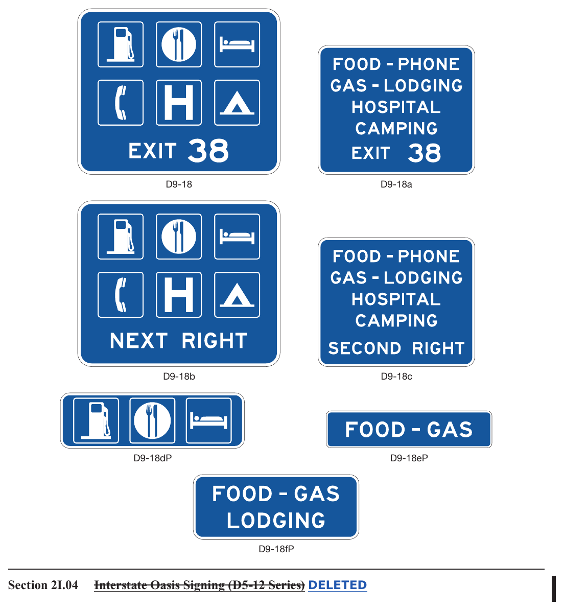
Signs shown: D9-18, D9-18a, D9-18b, D9-18c, D9-18dP, D9-18eP, D9-18fP, D5-12
§2I.04 Interstate Oasis Signing (D5-12 Series) DELETED¶
Figure 2I-4. Examples of Interstate Oasis Signs and Plaques DELETED
§2I.05 Rest Area and Other Roadside Area Signs (D5-1 through D5-11 Series)¶
Standard
01. Rest Area signs (see Figure 2I-5) shall have a retroreflective white legend and border on a blue background.
02. Signs that include the legend REST AREA shall be used only where parking and restroom facilities are available.
Guidance
03. A roadside area that does not contain restroom facilities should be signed to indicate the major road user service that is provided. For example, the sign legends for an area with only parking should use the words PARKING AREA (D5-9 series) instead of REST AREA. The sign legends for an area with only picnic tables and parking should use words such as PICNIC AREA instead of REST AREA.
04. Rest areas that have tourist information and Texas Travel Info Centers should be signed as provided in Section 2I.08.
05. Scenic area signing should be consistent with that provided for rest areas, except that the legends should use words such as SCENIC AREA, SCENIC VIEW, or SCENIC OVERLOOK (D5-11 series) instead of REST AREA.
06. If a rest area or other roadside area is provided on a conventional road, a D5-1T sign should be installed in advance of the rest area or other roadside area to permit the driver to reduce speed in preparation for leaving the highway. A D5-5T sign (or a D5-2 sign if an exit ramp is provided) should be installed at the turn-off point where the driver needs to leave the highway to access the rest area or other roadside area.
07. If a rest area or other roadside area is provided on a freeway or expressway, a D5-1 sign should be placed 1 mile and/or 2 miles in advance of the rest area.
Standard
08. A D5-2a sign shall be placed at the rest area or other roadside area exit gore.
Option
09. A D5-1a sign may be placed between the D5-1 sign and the exit gore on a freeway or expressway. A second D5-1 sign may be used in place of the D5-1a sign with a distance to the nearest ½ or ¼ mile displayed as a fraction rather than a decimal for distances of less than 1 mile.
10. To provide the road user with information on the location of succeeding rest areas, a Next Rest Area (D5-6) sign (see Figure 2I-5) may be installed independently or a Next Rest Area (D5-6PT) plaque may be mounted below one of the REST AREA advance guide signs.
Standard
11. All signs on freeways and expressways for rest and other roadside areas shall have letter and numeral sizes that comply with the minimum requirements of Tables 2E-4A and 2E-5. The sizes for General Service signs that have standardized designs shall be as shown in Table 2I-1.
Option
12. If the rest area has facilities for persons with disabilities (see Section 2I.02), the International Symbol of Accessibility (D9-6) sign (see Figure 2I-1) may be placed with or beneath an advance guide sign for the rest area.
13. If telecommunication devices for the deaf (TDD) are available at the rest area, the TDD (D9-21) symbol sign (see Figure 2I-1) may be used to supplement the advance guide signs for the rest area.
14. If wireless Internet services are available at the rest area, the Wireless Internet (D9-22) symbol sign (see Figure 2I-1) may be used to supplement the advance guide signs for the rest area.
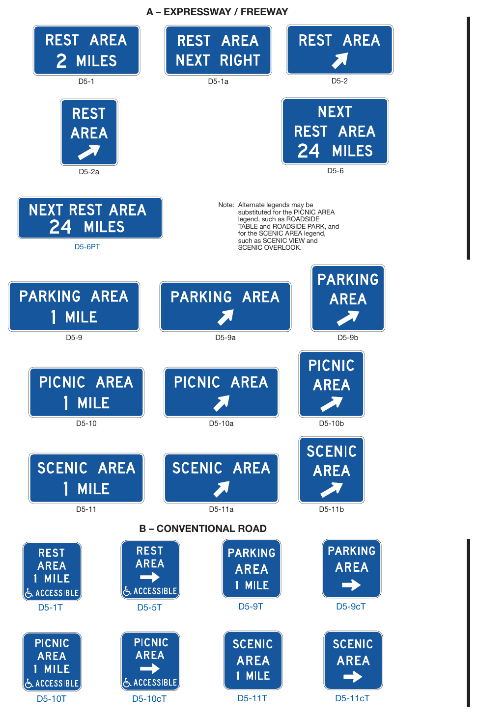
Signs shown: D5-1, D5-1a, D5-2, D5-2a, D5-6, D5-6PT, D5-9, D5-9a, D5-9b, D5-10, D5-10a, D5-10b, D5-11, D5-11a, D5-11b, D5-1T, D5-5T, D5-9T, D5-9cT, D5-10T, D5-10cT, D5-11T, D5-11cT
§2I.06 Brake Check Area Signs (D5-13 and D5-14) DELETED¶
Figure 2I-6. Brake Check Area and Chain-Up Area Signs DELETED
§2I.07 Chain-Up Area Signs (D5-15 and D5-16) DELETED¶
§2I.08 Tourist Information and Texas Travel Info Center Signs (D5-7 Series and D5-8)¶
Support
01. Tourist information and Texas Travel Info Centers have been constructed within rest areas on freeways and expressways and are operated by either the State or a private organization. Others have been located within close proximity to these facilities and operated by civic clubs, chambers of commerce, or private enterprise.
Guidance
02. The number of supplemental sign panels installed with Tourist Information or Texas Travel Info Center signs should be limited to three so as not to impose an undue informational load on the road user.
Standard
03. Tourist Information or Texas Travel Info Center signs (see Figure 2I-7) shall have a white legend and border on a blue background. Continuously staffed or unstaffed operation at least 8 hours per day, 7 days per week, shall be required.
04. If operated only on a seasonal basis, the Tourist Information or Texas Travel Info Center signs shall be removed or covered during the off seasons.
Guidance
05. For freeway or expressway rest area locations that also serve as tourist information or Texas Travel Info Centers, the following signing criteria should be used:
- A. The locations for tourist information and Texas Travel Info Center Advance Guide, Exit Direction, and Exit Gore signs should meet the General Service signing requirements described in Section 2I.03.
- B. If the signing for the tourist information or Texas Travel Info Center is to be accomplished in conjunction with the initial signing for the rest areas, the message on the Rest Area Tourist Info Center Advance (D5-7) sign should be REST AREA, TOURIST INFO CENTER, XX MILES or REST AREA, TEXAS TRAVEL INFO CENTER, XX MILES. On the Rest Area Tourist Info Center Entrance Direction (D5-8 or D5-7T) sign the message should be REST AREA, TOURIST INFO CENTER with a diagonally upward-pointing directional arrow (or NEXT RIGHT), or REST AREA, TEXAS TRAVEL INFO CENTER with a diagonally upward-pointing directional arrow (or NEXT RIGHT).
- C. If the initial rest area Advance Guide and Exit Direction signing is in place, these signs should include, on supplemental signs, the legend TOURIST INFO CENTER or, TEXAS TRAVEL INFO CENTER.
- D. The Exit Gore sign should contain only the legend REST AREA with the arrow and should not be supplemented with any legend pertaining to the tourist information center or Texas Travel Info Center.
Option
06. As an alternative, the Tourist Information (D9-10) sign (see Figure 2I-1) may be appended to the guide signs for the exit that provides access to the tourist information center. As a second alternative, the Tourist Information sign may be combined with General Service signing.
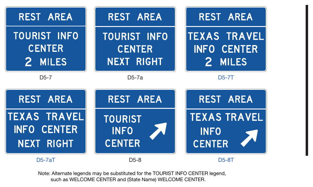
Signs shown: D5-7, D5-7a, D5-7T, D5-7aT, D5-8, D5-8T, D12-1, D12-1a
§2I.09 Radio Information Signing (D12-1 Series)¶
Option
01. A Radio-Weather Information (D12-1) sign (see Figure 2I-8) may be used in areas where difficult driving conditions commonly result from weather systems. Radio-Traffic Information (D12-1a) signs may be used in conjunction with traffic management systems.
Standard
02. Radio-Weather and Radio-Traffic Information signs shall have a white legend and border on a blue background. Only the numerical indication of the radio frequency shall be used to identify a station broadcasting travel-related weather or traffic information. No more than three frequencies shall be displayed on each sign. Only radio stations whose signal will be of value to the road user and who agree to broadcast either of the following two items shall be identified on Radio-Weather and Radio-Traffic Information signs:
- A. Periodic weather warnings at a rate of at least once every 15 minutes during periods of adverse weather; or
- B. Driving condition information (affecting the roadway being traveled) at a rate of at least once every 15 minutes, or when required, during periods of adverse traffic conditions, and when supplied by an official agency having jurisdiction.
03. If a station to be considered operates only on a seasonal basis, its signs shall be removed or covered during the off season.
Guidance
04. The radio station should have a signal strength to adequately broadcast at least 70 miles along the route. Signs should be spaced as needed for each direction of travel at distances determined by an engineering study. The stations to be included on the signs should be selected in cooperation with the association(s) representing major broadcasting stations in the area to provide: (1) maximum coverage to all road users on both AM and FM frequencies; and (2) consideration of 24 hours per day, 7 days per week broadcast capability.
Option
05. The URGENT MESSAGE WHEN FLASHING (D12-1bP) plaque may be mounted below the D12-1 or D12-1a sign if supplemented by Warning Beacons (see Section 4S.03) that flash only when a message related to adverse travel conditions is being broadcast.
07. In roadway rest area locations, a smaller sign using a greater number of radio frequencies, but of the same general design, may be used.
Standard
Radio-Weather and Radio-Traffic Information signs installed in rest areas shall be positioned such that they are not visible from the main roadway.
§2I.10 Channel 9 Monitored Sign (D12-3)¶
Option
01. A Channel 9 Monitored (D12-3) sign (see Figure 2I-8) may be installed as needed. Official public agencies or their designees may be displayed as the monitoring agency on the sign.
Standard
02. Only official public agencies or their designee shall be displayed as the monitoring agency on the Channel 9 Monitored sign.
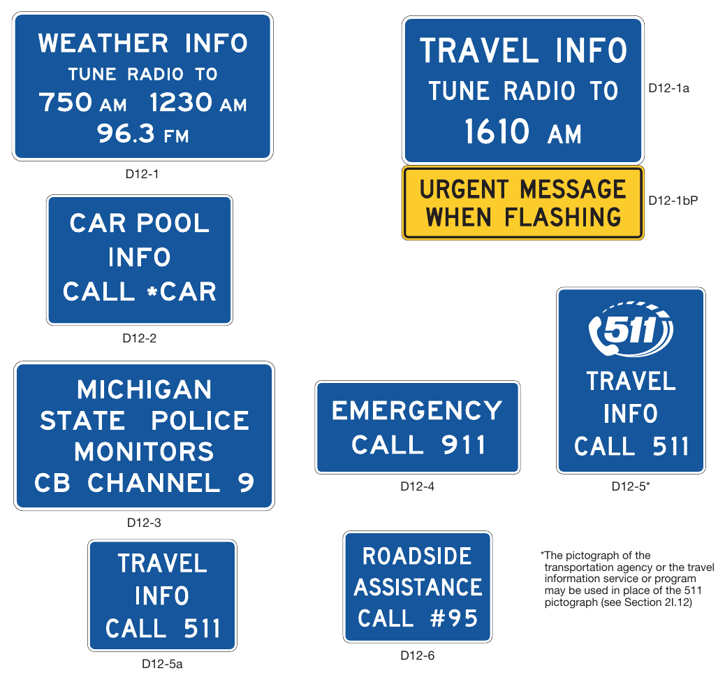
Signs shown: D12-1a, D12-1, D12-1bP, D12-2, D12-4, D12-5, D12-3, D12-6, D12-5a
§2I.11 EMERGENCY CALL 911 Sign (D12-4)¶
Option
01. An EMERGENCY CALL 911 (D12-4) sign (see Figure 2I-8) may be used for cellular telephone communications.
§2I.12 TRAVEL INFO CALL 511 Signs (D12-5 and D12-5a)¶
Option
01. A TRAVEL INFO CALL 511 (D12-5 or D12-5a) sign (see Figure 2I-8) may be installed if a 511 travel information services telephone number is available to road users for obtaining traffic, public transportation, weather, construction, or road condition information.
02. The pictograph of the transportation agency or the travel information service or program that is providing the travel information may be displayed in place of the 511 pictograph on the D12-5 sign above the TRAVEL INFO CALL 511 legend.
Standard
03. The logo of a commercial entity shall not be incorporated within the TRAVEL INFO CALL 511 signs.
04. If the pictograph of the transportation agency or the travel information service or program is used in place of the 511 pictograph on the D12-5 sign (see Paragraph 2 of this Section), the maximum height of the pictograph shall not exceed the height of the 511 pictograph on the standard sign size specified for the roadway classification in Table 2H-1.
05. The TRAVEL INFO CALL 511 signs shall have a white legend and border on a blue background.
§2I.13 Roadside Assistance Sign (D12-6)¶
Option
01. A Roadside Assistance (D12-6) sign (see Figure 2I-8) displaying the Highway Assistance cellular telephone code designated for that roadway or jurisdiction may be used along a highway that is served by an authorized roadside assistance program with authorized service vehicles and personnel that provide roadside vehicle repair assistance to road users free of charge.
§2I.14 Carpool and Ridesharing Signing (D12-2)¶
Option
01. In areas having carpool matching services, a Carpool Information (D12-2) sign (see Figure 2I-8) may be provided adjacent to highways with preferential lanes or along any other highway.
02. Carpool Information signs may include an Internet domain name or telephone number of more than four characters within the legend.
Standard
03. If a local transit pictograph or carpool symbol is incorporated into the Carpool Information sign, the maximum vertical dimension of the pictograph or symbol shall not exceed 18 inches and the maximum horizontal dimension shall not exceed 30 inches.
§2I.15 Signing for Truck Parking Availability (D9-16b through D9-16e)¶
Option
01. General Service signs may be used to display the number of available truck parking spaces at roadside areas such as rest areas, Texas Travel Info Centers, and weigh stations, and at facilities off a highway that are open to the public and provide parking for commercial vehicles 24 hours per day, 7 days per week.
Standard
02. The Truck Parking Availability General Service (D9-16b through D9-16e) signs (see Figure 2I-9) shall include a changeable message element with a white changeable legend on a black opaque background that displays only the number of parking spaces currently available at each location or the legend FULL. The upper section of the sign shall display the Truck Parking (D9-16) symbol sign and the legend SPACES OPEN. The sign shall display the number of available truck parking spaces for no more than three parking facilities. Where two lines of legend, such as the location and a distance, are displayed for a parking facility, not more than two parking facilities shall be displayed on the sign.
03. Where the truck parking facility is located off the main highway and is accessed from the crossroad, directional assemblies with the Truck Parking (D9-16) sign shall be installed along the ramp and along crossroads where the route to the facility requires a turn, where it is unclear as to which roadway to follow, or where additional guidance is needed.
Support
04. Displaying the number of parking spaces available at a facility when the number is low could result in truckers choosing to continue to a distant facility that no longer has available space by the time they arrive.
Option
05. The word FULL in a white legend may be displayed on changeable message elements of a Truck Parking Availability General Service sign when the number of truck parking spaces available at the associated facility reaches a predetermined lower threshold.
Guidance
06. Truck Parking Availability signs should be located 3 to 5 miles in advance of the nearest parking facility. The parking facilities displayed on the sign should be no more than 60 miles from the sign location.
Support
07. Examples of uses of Truck Parking Availability signs are shown in Figure 2I-10.
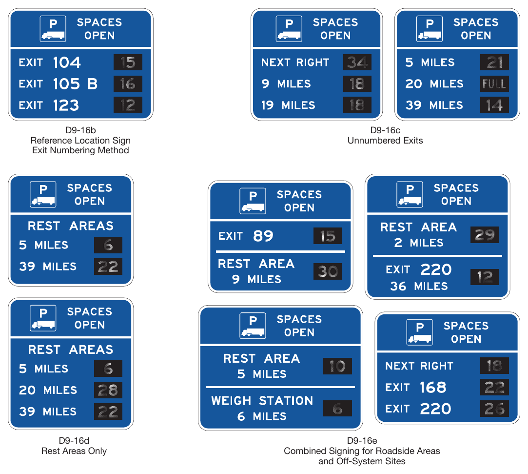
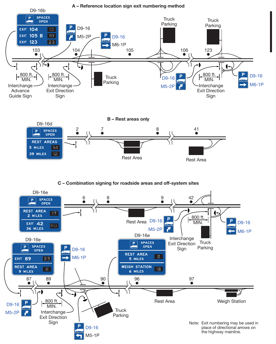
Signs shown: D9-16b, D9-16, M5-2P, M6-1P, D9-16d, D9-16e, M5-1P
Chapter 2J. SPECIFIC SERVICE SIGNS¶
§2J.01 Eligibility¶
Standard
01. Specific Service (Logo) signs shall be defined as guide signs that provide road users with business identification and directional information for eligible services. Eligible service categories shall be limited to gas, food, lodging, camping, and electric vehicle (EV) charging.
Guidance
02. The use of Specific Service signs should be limited to areas primarily rural in character with adequate space for all signs to be properly accommodated. General Service signs for gas, EV charging, food, lodging, and camping should not be used on roadways eligible for Specific Service signs.
03. Specific Service signs should not be installed at an interchange where the road user cannot conveniently reenter the freeway or expressway and continue in the same direction of travel.
Standard
04. Eligible service facilities shall comply with laws concerning the provisions of public accommodations without regard to race, religion, color, age, sex, or national origin, and laws concerning the licensing and approval of service facilities.
Guidance
05. Except as provided in Paragraph 6 of this Section, distances to eligible services should not exceed 3 miles in any direction.
Option
06. If, within the 3-mile limit, facilities for the services being considered are not available or choose not to participate in the program, the limit of eligibility may be extended in 3-mile increments until one or more facilities for the services being considered chooses to participate, or until 15 miles is reached, whichever comes first.
Standard
07. If State or local agencies elect to provide Specific Service signing, there shall be a statewide policy for such signing and criteria for the eligibility and availability of the various types of services.
Guidance
08. The criteria for the statewide policy should consider the following:
- A. To qualify for a GAS business identification sign panel, a business should have:
- 1. Vehicle services including gasoline, oil, and water;
- 2. Continuous operation at least 16 hours per day, 7 days per week for freeways and expressways, and continuous operation at least 12 hours per day, 7 days per week for conventional roads; and
- 3. Modern sanitary facilities and drinking water.
- B. To qualify for a FOOD business identification sign panel, a business should have:
- 1. Licensing or approval, where required;
- 2. Continuous operations to serve at least 2 meals per day, at least 6 days per week; and
- 3. Modern sanitary facilities.
- C. To qualify for a LODGING business identification sign panel, a business should have:
- 1. Licensing or approval, where required;
- 2. Adequate sleeping accommodations; and
- 3. Modern sanitary facilities.
- D. To qualify for a CAMPING business identification sign panel, a business should have:
- 1. Licensing or approval, where required;
- 2. Adequate parking accommodations; and
- 3. Modern sanitary facilities and drinking water.
Option
09. Major shopping areas may be included in a Specific Service signing program.
Standard
10. To be eligible for an Electric Vehicle (EV) CHARGING business identification sign panel, the EV chargers provided shall meet the criteria for Direct Current Fast Chargers provided in 23 CFR 680.106 and be in continuous operation at least 16 hours per day, 7 days per week.
Option
11. Business identification sign panels for a proprietary electric vehicle charging service may be included on an EV Charging Specific Service sign if it meets the eligibility criteria in Paragraph 10 of this Section.
Support
12. Section 2J.12 contains additional information on criteria for the statewide policy regarding signing.
§2J.02 Application¶
Support
01. Examples of Specific Service signs are shown in Figure 2J-1.
02. Examples of sign locations are shown in Figure 2J-2.
Standard
03. The number of Specific Service signs along an approach to an interchange, regardless of the number of service types displayed, shall be limited to a maximum of four. Except as provided in Paragraph 4 of this Section, in the direction of traffic flow, successive Specific Service signs shall be for camping, lodging, food, EV charging, and gas services, in that order.
Option
04. When spacing does not allow EV Charging Specific Service signs to be located as described in Paragraph 3 of this Section, then the EV Charging Specific Service signs may be located anywhere within the successive Specific Service sign order where adequate spacing between signs allows.
Guidance
05. The Specific Service signs should be located to take advantage of natural terrain, to have the least impact on the scenic environment, and to avoid visual conflict with other signs within the highway right-of-way.
06. Where a service type is displayed on two signs, the signs for that service should follow one another in succession.
Standard
07. A Specific Service sign shall display the word message GAS, EV CHARGING, FOOD, LODGING, or CAMPING, an appropriate directional legend such as the word message EXIT XX, NEXT RIGHT, SECOND RIGHT (for double exit interchanges), or directional arrows, and the related business identification sign panels. Distances to eligible facilities shall not be displayed on the Specific Service signs on the approach to an interchange.
08. A business that does not offer gasoline, but offers alternative fuels, shall not be signed using GAS Specific Service signs.
Option
09. A business that does not offer gasoline but offers alternative fuels may be signed using General Service signs for the alternative fuel provided.
Support
10. General Service signs for facilities providing alternative fuels, including EV charging, compressed natural gas, liquefied natural gas, liquefied petroleum gas, and hydrogen, are provided in Chapter 2I.
Standard
11. No more than three types of services shall be represented on any sign or sign assembly and no more than six business identification sign panels shall be displayed on any one sign. If three types of services are displayed on one sign, then the business identification sign panels shall be limited to two for each service type (for a total of six business identification sign panels). If two types of services are displayed on one sign, then the business identification sign panels shall be limited to either three for each service type, or four for one service type and two for the other service type (for a total of six business identification sign panels in either case). The legend and business identification sign panels applicable to a service type shall be displayed such that the road user will not associate them with another service type on the same sign. Other configurations or arrangements of business identification sign panels shall not be allowed.
12. No service type shall appear on more than two signs (see Paragraph 6 of this Section).
13. The Specific Service signs shall have a blue background, a white border, and white legends of uppercase letters, numerals, and arrows.
Guidance
14. If a service type is no longer available from an interchange, the Specific Service sign should be removed when the business identification sign panels are removed. If a sign is to remain, but the service type is no longer available, then the service type legend should be covered so that road users do not misinterpret the sign as a General Service sign implying that the service is available.
15. A Specific Service sign should not be installed unless a service type is currently available from an interchange.
Option
16. If there is indication that a service type will again be available in the near future, the sign may be covered, in accordance with Paragraph 14 of this Section, rather than removed.
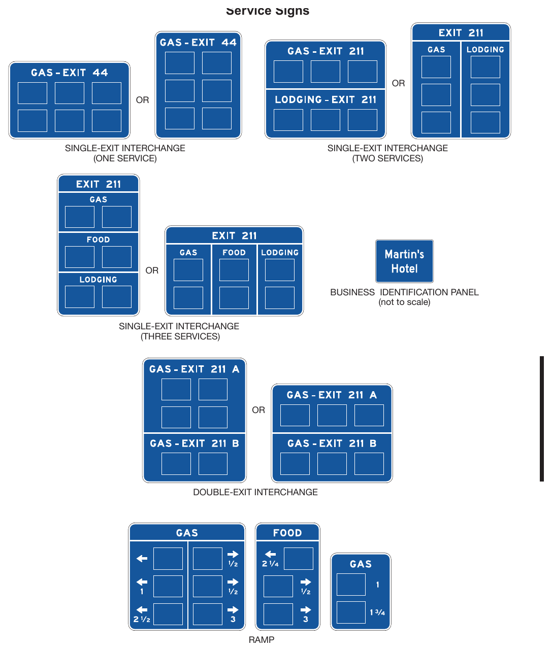
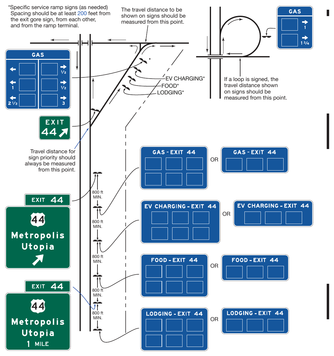
§2J.03 Logos and Business Identification Sign Panels¶
Standard
01. A business identification sign panel legend shall be either an identification trademark or a word message of the business’s name. Each logo or word message shall be placed on a separate business identification sign panel that shall be attached to the Specific Service sign. Logos or trademarks used alone for a business identification sign panel shall be reproduced in the colors and general shape consistent with customary use, and any integral legend shall be in proportionate size. A logo that resembles an official traffic control device shall not be used.
02. Scanning graphics that are visible to the road user from the roadway for the purpose of obtaining information shall not be displayed on business identification sign panels, including on any logo displayed thereupon.
Guidance
03. The logo or trademark used on a business identification sign panel should be consistent with the on-premise business identification signs at the location of the business that are visible from the roadway.
04. A word message business identification sign panel that does not use a logo or trademark should have a blue background with a white legend and border.
Support
05. Section 2J.05 contains information regarding the minimum letter heights for business identification sign panels.
Option
06. A portion of a business identification sign panel may be used to display a supplemental message horizontally along the bottom of the business identification sign panel, provided that the message displays essential motorist information consistent with the service category type and related to the operation of the business (see Figure 2J-4).
Standard
07. All supplemental messages shall be displayed within the business identification sign panel and shall have letters and numerals that comply with the minimum height requirements shown in Table 2J-1. Supplemental messages promoting the availability of products, amenities, or services that are not directly related to the service category and/or those not available to non-patrons of the primary service provided for the service category, such as car wash, automated teller machines, Internet, lottery, or swimming pool, shall not be displayed on business identification sign panels.
08. Messages related to the promotion or availability of business identification sign panel space shall not be displayed on Specific Service signs.
Table 2J-1. Minimum Letter and Numeral Sizes for Specific Service Signs According to Sign Type
| A. Specific Service Signs | ||
|---|---|---|
| Service Categories | 10 | 6 |
| Exit Number Words | 10 | — |
| Exit Number Numerals and Letters | 10 | — |
| Action Message Words | 10 | 6 |
| Distance Numerals | — | 6 |
| Distance Fraction Numerals | — | 4 |
| B. Business Identification Sign Panels | ||
| Words and Numerals (Non-Trademark/Graphic Logo) | 8 | 4 |
| Trademark/Graphic Logo | Proportional | Proportional |
| Supplemental Message Words and Numerals | 5 | 2.5 |
09. To be eligible for an EV CHARGING supplemental message on a business identification sign panel, the business shall:
- A. Offer electric vehicle charging to the general public without purchasing the primary service (gas, food, lodging, camping, or attraction, as appropriate); and
- B. For the service categories of gas, food, and attraction, provide EV chargers meeting the criteria for Direct Current Fast Chargers (DCFC) provided in 23 CFR 680.106; or
- C. For the service categories of camping and lodging, provide EV chargers meeting the criteria for DCFCs provided in 23 CFR 680.106 and/or AC Level 2 Charging.
Option
10. A Supplemental message identifying an alternative fuel available may be added only to the business identification sign panels on the GAS Specific Services sign for gasoline facilities that provide the specified alternative fuel in addition to gasoline.
11. The Supplemental message EV CHARGING may be added to a business identification sign panel for the service categories of gas, food, lodging, or camping in accordance with the criteria in Paragraph 9 of this Section.
Guidance
12. A business identification sign panel should not display more than one supplemental message.
13. The supplemental message should be displayed in a black legend on a yellow background for that portion of the business identification sign panel.
Option
14. Typical supplemental messages may include DIESEL, LP-GAS, EV CHARGING, 24 HOURS, CLOSED SUNDAY, and RV ACCESS.
Standard
15. A business identification sign panel shall not display the identification logo/trademark or name of more than one business. A business identification sign panel shall not display more than one name or identification logo/trademark for the same business. Slogans, such as marketing slogans associated with the business, shall not be displayed on business identification sign panels or the Specific Service sign itself.
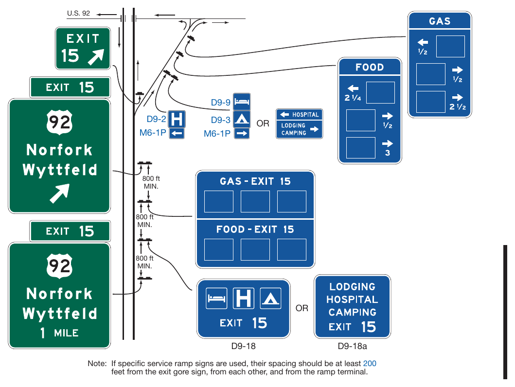
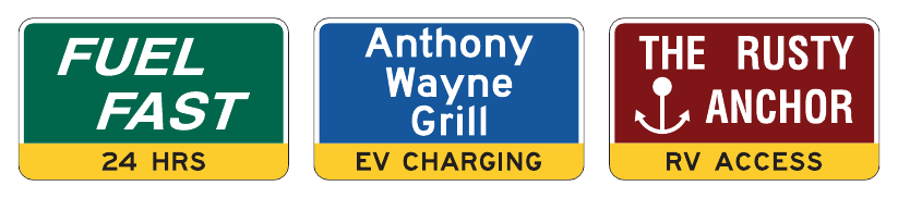
§2J.04 Number and Size of Signs and Business Identification Sign Panels¶
Guidance
01. Sign sizes should be determined by the amount and height of legend and the number and size of business identification sign panels attached to the sign. All business identification sign panels on a sign should be the same size.
Standard
02. Each Specific Service sign or sign assembly shall be limited to no more than six business identification sign panels.
Option
03. Where more than six businesses of a specific service type are eligible for business identification sign panels at the same interchange, additional business identification sign panels of that same specific service type may also be displayed in accordance with the provisions of Paragraph 4 of this Section. The additional business identification sign panels may be displayed either by placing more than one specific service type on the same sign (see Paragraph 11 of Section 2J.02) or by using a second Specific Service sign of that specific service type if the additional sign can be added without exceeding the limit of four Specific Service signs at an interchange approach (see Paragraph 3 of Section 2J.02).
Standard
04. Where business identification sign panels for more than six businesses of a specific service type are displayed at the same interchange approach, the following provisions shall apply:
- A. No more than 12 business identification sign panels of a specific service type shall be displayed on no more than two Specific Service signs or sign assemblies;
- B. No more than six business identification sign panels shall be displayed on a single Specific Service sign; and
- C. No more than four Specific Service signs shall be displayed on the approach.
Support
05. Section 2J.08 contains information regarding Specific Service signs for double-exit interchanges.
06. Section 2J.09 contains information regarding Specific Service signs for multiple interchanges that are accessed from collector-distributor roadways rather than from the highway mainline.
Standard
07. Each business identification sign panel attached to a Specific Service sign shall be a horizontally oriented rectangle with a width longer than the height. A business identification sign panel on signs for freeways and expressways shall not exceed 48 inches in width and 36 inches in height (see Table 2J-2). A business identification sign panel on signs for conventional roads and freeway and expressway ramps shall not exceed 24 inches in width and 18 inches in height (see Table 2J-2). The vertical and horizontal spacing between business identification sign panels shall not exceed 8 inches and 12 inches, respectively.
Support
08. Sections 2A.10, 2E.13, and 2E.14 contain information regarding borders, interline spacing, and edge spacing.
Table 2J-2. Maximum Business Identification Sign Panel Sizes by Roadway Classification
| Roadway Classification | Sign Panel Size |
|---|---|
| Freeway or Expressway | 48 x 36 |
| Conventional Road or Ramp | 24 x 18 |
Note: Sizes are shown in inches as width x height.
§2J.05 Size of Lettering¶
Standard
01. All Specific Service signs and business identification sign panels shall have letter and numeral sizes that comply with the minimum requirements of Table 2J-1.
Guidance
02. Any legend on a business identification graphic/trademark should be proportional to the size of the graphic/ trademark.
§2J.06 Signs at Interchanges¶
Standard
01. The Specific Service signs shall be installed between the preceding interchange and at least 800 feet in advance of the Exit Direction sign at the interchange from which the services are available (see Figure 2J-2).
02. Specific Service signs shall not be used at freeway-to-freeway interchanges (see Section 2E.37), except where the exit ramp also provides direct access to a conventional road within that interchange (see Figure 2J-5).
Guidance
03. There should be at least an 800-foot spacing between the Specific Service signs and other large guide signs, except for Specific Service ramp signs. Excessive spacing should not be used between Specific Service signs, as this is not desirable either. Specific Service signs should not be located closer together (in feet) than 5 to 7 times the speed limit (in mph) from other small or different purpose signs.
04. Specific Service ramp signs should be spaced at least 200 feet longitudinally beyond the Exit Gore sign, from each other, from the ramp terminal, and from any other traffic control device. Specific Service ramp signs should be spaced at least 200 feet longitudinally from any Destination guide signs along the ramp. Longer longitudinal spacing should be provided between Specific Service ramp signs and any warning or regulatory signs along the ramp, and any intersection traffic control devices at the ramp terminal.
05. When the distance to the next exit providing access to EV charging service is 50 miles or greater, the Next EV Charging (D9-17a) sign should be used (see Figure 2H-9). When used, the Next EV Charging sign should be located directly after the General Service sign for the fuel type displayed in the signing sequence for the exit (see Figure 2H-10).
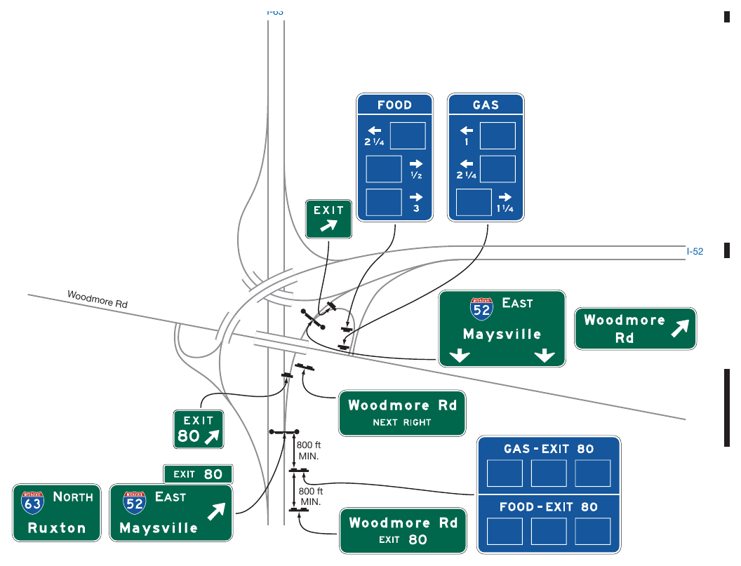
§2J.07 Single-Exit Interchanges¶
Standard
01. At numbered single-exit interchanges, the name of the service type followed by the exit number shall be displayed on one line above the business identification sign panels. At unnumbered interchanges, the directional legend NEXT RIGHT (LEFT) shall be used in place of the exit number.
02. At single-exit interchanges where traffic is allowed to turn onto the crossroad in either direction from the ramp, Specific Service ramp signs shall be installed along the ramp or opposite the ramp terminal for facilities that have business identification sign panels displayed along the main roadway if the facilities are not readily visible from the ramp terminal. Directions to the service facilities shall be indicated by arrows on the ramp signs. Business identification sign panels on Specific Service ramp signs shall be duplicates of those displayed on the Specific Service signs located in advance of the interchange, but shall be reduced in size (see Paragraph 7 of Section 2J.04).
Option
03. Specific Service ramp signs may display distances (see Paragraphs 14 and 15 of Section 2A.08) to a service facility when the facility is not visible from ramp intersection with the crossroad.
04. An exit number plaque (see Section 2E.22) may be used instead of the exit number on the signs located in advance of an interchange.
§2J.08 Double-Exit Interchanges¶
Guidance
01. At double-exit interchanges, the Specific Service signs should consist of two sections, one for each exit (see Figure 2J-1).
Standard
02. At a double-exit interchange, the top section shall display the business identification sign panels for the first exit and the bottom section shall display the business identification sign panels for the second exit. At numbered interchanges, the name of the service type and the exit number shall be displayed above the business identification sign panels in each section. At unnumbered interchanges, the word message NEXT RIGHT (LEFT) and SECOND RIGHT (LEFT) shall be used in place of the exit number. The number of business identification sign panels on the sign (total of both sections) or the sign assembly shall be limited to six.
Guidance
03. At a double-exit interchange, where a service type is displayed on two Specific Service signs in accordance with the provisions of Section 2J.04, one of the signs should display the business identification sign panels for that service type for the businesses that are accessible from one of the two exits and the other sign should display the business identification sign panels for that service type for the businesses that are accessible from the other exit.
Option
04. At a double-exit interchange where there are four business identification sign panels to be displayed for one of the exits and one or two business identification sign panels to be displayed for the other exit, the business identification sign panels may be arranged in three rows with two business identification sign panels per row.
05. At a double-exit interchange, where a service is to be signed for only one exit, one section of the Specific Service sign may be omitted, or a single exit interchange sign may be used.
06. Signs on ramps and crossroads as described in Section 2J.07 may be used at a double-exit interchange.
§2J.09 Collector-Distributor Roadways for Successive Interchanges¶
Support
01. Examples of Specific Service signs used in advance of interchanges for collector-distributor roadways that provide access to multiple interchanges are shown in Figure 2J-6.
Option
02. If services are available from more than one of the interchanges along the collector-distributor roadway and those services are signed with Specific Service signs as described in Paragraph 4 of this Section, then Specific Service signs may be used on the mainline in conformance with the provisions of this Chapter.
Standard
03. No more than four Specific Service signs shall be displayed on a highway mainline approach to a collector-distributor roadway.
04. If Specific Service signs are located on the highway mainline for services accessed from the collector-distributor roadway, then the business identification sign panels displayed on the collector-distributor roadway shall be only duplicates of those displayed on the highway mainline.
05. If more than four Specific Services signs would be required on the mainline in advance of the collector-distributor roadway in order to display all the business identification sign panels used on Specific Service signs in advance of the collector-distributor roadway exits, then General Service signs shall be used on the mainline to identify the types of services displayed on Specific Service signs on the collector-distributor roadway.
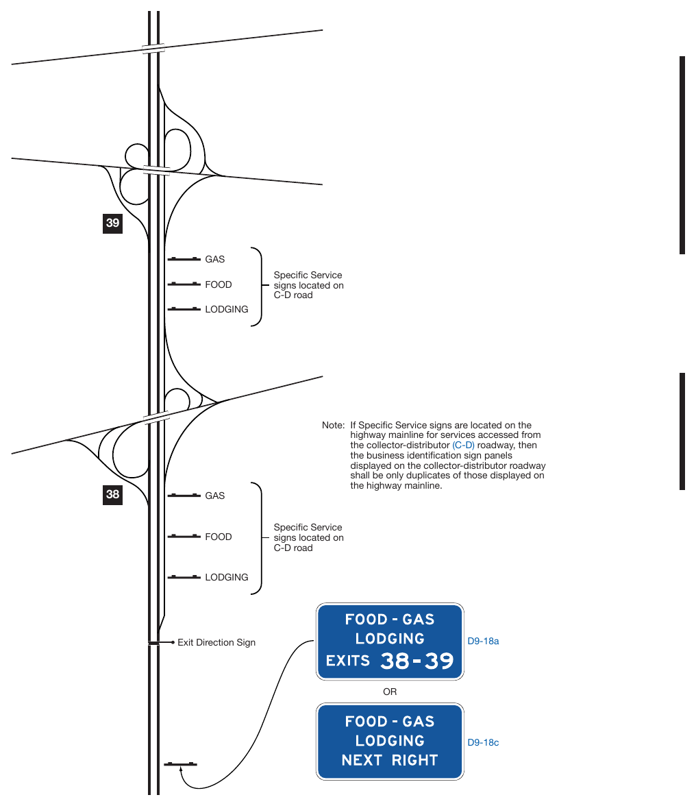
§2J.10 Specific Service Trailblazer Signs DELETED¶
Figure 2J-7. Examples of Specific Service Trailblazer Signs DELETED
§2J.11 Signs at Intersections DELETED¶
§2J.12 Signing Policy¶
Support
01. Additional regulations for Specific Service signs are contained in 43 Texas Administrative Code, Sections 25.400 through 25.409.
Chapter 2K. TOURIST-ORIENTED DIRECTIONAL SIGNS¶
§2K.01 Purpose and Application¶
Support
01. Tourist-oriented directional signs are post-mounted guide sign assemblies with one or more signs that display the business identification of and directional information for eligible business, service, and activity facilities.
Standard
02. A facility shall be eligible for tourist-oriented directional signs only if it derives its major portion of income or visitors during the normal business season from road users not residing in the area of the facility.
Option
03. Tourist-oriented directional signs may include businesses involved with seasonal agricultural products.
Standard
04. The use of tourist-oriented directional signs shall be limited to rural highways (see definition in Section 1C.02). Tourist-oriented directional signs shall not be installed on conventional roads in urban or urbanized areas or on freeway or expressway main roadways or ramps.
Guidance
If a sign is to be displayed for a facility that is eligible for a tourist-oriented directional sign and a general service sign (see section 2I.02), the tourist-oriented directional sign should be displayed.
§2K.02 Design¶
Standard
01. Tourist-oriented directional sign assemblies shall have one or more signs (see Figure 2K-1) for the purpose of displaying the business identification of and directional information for eligible facilities. Except as provided in Paragraph 5 of this Section, each sign shall be rectangular in shape and shall have a white legend and border on a blue background.
02. The content of the legend on each sign shall be limited to the identification and directional information for no more than one eligible business, service, or activity facility. The legends shall not include promotional advertising.
Guidance
03. Each sign should have a maximum of two lines of legend including no more than one symbol (see Paragraph 4 of this Section), a separate directional arrow, and the distance to the facility displayed beneath the arrow. Arrows pointing to the left or up should be at the extreme left of the sign. Arrows pointing to the right should be at the extreme right of the sign. Symbols, when used, should be to the left of the word legend (see Paragraph 7 of this Section).
Option
04. The General Service sign symbols (see Section 2I.02) and the symbols for recreational and cultural interest area signs (see Chapter 2M) may be used on tourist-oriented directional signs.
Standard
05. When used, recreational and cultural interest area symbols shall be white on a brown background.
06. When used, symbols shall be an appropriate size (see Section 2K.04).
07. Symbols resembling official traffic control devices shall not be permitted. All symbols shall be approved by TxDOT before they are displayed on a tourist-oriented directional sign.
Option
08. The word message TOURIST ACTIVITIES may be displayed at the top of the tourist-oriented directional sign assembly.
Standard
09. The TOURIST ACTIVITIES word message shall have a white legend in all upper-case letters and a white border on a blue background. If used, it shall be placed above and in addition to the directional signs.
Support
12. Examples of tourist-oriented directional signs are shown in Figures 2K-1 and 2K-2.
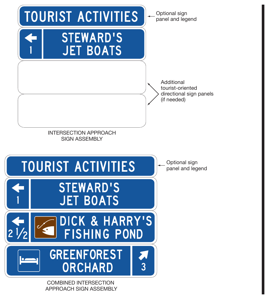
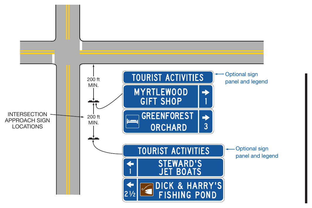
§2K.03 Style and Size of Lettering¶
Guidance
01. All letters and numbers on tourist-oriented directional signs should be upper-case and at least 6 inches in height.
Standard
Design standards for letters, numerals, and spacing shall be as provided in the “Standard Highway Sign Designs for Texas” publication (see Section 1A.05).
§2K.04 Arrangement and Size of Signs¶
Standard
01. The total height of the tourist-oriented directional signs in a sign assembly shall be limited to a maximum of 6 feet. Additional height shall be allowed to accommodate the addition of the optional TOURIST ACTIVITIES message provided in Section 2K.02.
Guidance
02. The number of intersection approach sign assemblies (one sign assembly for tourist-oriented destinations to the left, one for destinations to the right, and one for destinations straight ahead) installed in advance of an intersection should not exceed three. The number of signs installed in each assembly should not exceed three. Except as provided in Paragraph 5 of this Section, the signs for right-turn, left-turn, and straightthrough destinations should be on separate sign assemblies. Signs for facilities in the straight-through direction should be considered only when there are signs for destinations in either the left or right direction.
03. If it has been determined to be appropriate to combine the left-turn and right-turn destination signs on a single sign assembly, the left-turn destination signs should be above the right-turn destination signs (see Figure 2K-1). When there are multiple destinations in the same direction, they should be in order based on their distance from the intersection. Except as provided in Paragraph 5 of this Section, a straight-through sign should not be combined in a sign assembly displaying left-turn and/or right-turn destinations.
05. The signs should not exceed the size necessary to accommodate two lines of legend without crowding. Symbols on a directional sign should not exceed the height of two lines of a word legend. All directional signs and other parts of the sign assembly should be the same width, which should not exceed 6 feet.
Option
At intersection approaches where three or fewer facilities are displayed, the left-turn, right-turn, and straightthrough destination sign panels may be combined on the same sign.
§2K.05 Advance Signs DELETED¶
§2K.06 Sign Locations¶
Guidance
01. The intersection approach signs should be located at least 200 feet in advance of the intersection. Sign assemblies should be spaced at least 200 feet apart and at least 200 feet from other traffic control devices.
02. Position, height, and lateral offset of sign assemblies should be governed by Chapter 2A except as permitted in this Section.
Option
04. Tourist-oriented directional signs may be placed farther from the edge of the road than other traffic control signs.
Standard
05. The location of other traffic control devices shall take precedence over the location of tourist-oriented directional signs.
§2K.07 State Policy¶
Standard
01. To be eligible for tourist-oriented directional signing, facilities shall comply with applicable State and Federal laws concerning the provisions of public accommodations without regard to race, religion, color, age, sex, or national origin, and with laws concerning the licensing and approval of service facilities. Each State that elects to use tourist-oriented directional signs shall adopt a policy that complies with these provisions.
Support
02. Additional regulations for tourist-oriented directional signs are contained in 43 Texas Administrative Code, Chapter 25, Subchapter G (Section 25.400 through 25.409).
Chapter 2L. CHANGEABLE MESSAGE SIGNS¶
§2L.01 Description of Changeable Message Signs¶
Support
01. A changeable message sign (CMS) is a traffic control device that is capable of displaying one or more alternative messages. Some CMS have a blank mode when no message is displayed, while others display multiple messages with only one of the messages displayed at a time (such as OPEN/CLOSED signs at Commercial Motor Vehicle (CMV) stations). Changeable message signs are referred to as Dynamic Message Signs (DMS) in the National Intelligent Transportation Systems (ITS) Architecture and are referred to as Variable Message Signs (VMS) in the National Electrical Manufacturers Association (NEMA) standards publication.
02. The provisions in this Chapter apply to both permanent and portable changeable message signs (PCMS) with electronic displays or the electronic display portion of an otherwise conventional static sign. Additional provisions that only apply to PCMS can be found in Section 6L.05. The provisions in this Chapter generally do not apply to CMS with non-electronic displays that are changed either manually or electromechanically, such as a hinged-panel, rotating-drum, or back-lit curtain or scroll CMS.
03. The CMS is a traffic control device at all times regardless of the type of message being displayed. Accordingly, the limitations on design, format, and manner of display of a message conveyed on a conventional sign apply to CMS regardless of the type of message being displayed at any given time. Some of the general provisions regarding traffic control devices are reiterated in this Chapter. However, this Chapter is not an independent or stand-alone reference for CMS. Users of CMS are expected to consult the other chapters in this Manual for criteria on how to develop effective messages that comply with this Manual and that meet the expectancy and limitations of the road user. In this regard, the engineering processes applied to decisions about whether to use a particular sign, for example, are no different for the decisions about the type and content of the message under consideration for display on a CMS. The other limited-use messages allowed on CMS as provided for in this Chapter likewise fall under the same MUTCD provisions as the primary-use traffic operation regulatory, warning, and guidance messages except as stated otherwise in this Chapter.
04. CMS messaging can be subject to habituation, a phenomenon by which repeated exposure to a stimulus results in diminished response. CMS habituation can occur through repeated exposure to messages, especially those messages that might not be perceived as having relevance to the road user, resulting in diminished responsiveness of the road user to that message. Because messages can be changed or extinguished, the effectiveness of CMS is tied more to the messages displayed thereon, the frequency of displayed messages, and the relevance to the road user, rather than to the installation of the signs themselves.
Guidance
05. Changeable message signs should be used judiciously to avoid habituation and preserve their effectiveness during the display of real-time messages about traffic conditions or traffic advisories.
Standard
06. The design of legends for non-electronic display CMS shall comply with the provisions of Chapters 2A through 2K, 2M, and 2N of this Manual. Other CMS shall comply with the design and application principles established in this Chapter, Chapter 2A, and provisions elsewhere in this Manual for specific signs.
07. No items other than inventory or maintenance-related information (see Section 2A.04) shall be displayed on the front or back of a CMS or portable CMS. Names or logos of the manufacturer, brand, or model shall not be displayed on a CMS or portable CMS, either in the message display itself or on the exterior housing.
Guidance
08. Blank-out signs that display only single-phase, predetermined electronic-display legends that are limited by their composition and arrangement of pixels or other illuminated forms in a fixed arrangement (such as a blank-out sign indicating a part-time turn prohibition, a blank-out or changeable lane-use sign, or a changeable OPEN/CLOSED sign for a CMV inspection station) should comply with the provisions of the applicable Section for the specific type of sign, provided that the letter forms, symbols, and other legend elements are duplicates of the conventional messages as detailed in the “Standard Highway Sign Designs for Texas” publication (see Section 1A.05). Because such a sign is effectively an illuminated version of a conventional sign, the size of its legend elements, the overall size of the sign, and the placement of the sign should comply with the applicable provisions for the conventional version of the sign.
§2L.02 Applications of Changeable Message Signs¶
Standard
01. CMS shall display only traffic operational, regulatory, warning, and guidance information except as otherwise provided in this Chapter. Advertising or other messages not related to traffic control shall not be displayed on a CMS or on its supports or other equipment.
Option
02. CMS may display traffic safety campaign messages (see Section 2L.07), transportation-related messages, emergency homeland security messages, and alert messages as permitted by state or federal law including America’s Missing: Broadcast Emergency Response (AMBER) (Texas Gov't Code Ch. 411, Subch. L), Silver (Gov’t Code Ch. 411, Subch. M), Blue (Gov’t Code Ch. 411, Subch. P), Endangered Missing Persons (Gov’t Code Ch. 411, Subch. L), Coordinated Law Enforcement Adult Rescue (CLEAR) (Gov’t Code Ch. 411, Subch. Q), Power Outage (Gov’t Code Ch. 411, Subch. K-1), and Active Shooter (Gov’t Code Ch. 411, Subch. L-1), all as provided for in this Chapter.
03. Transportation-related messages for the purpose of improving traffic conditions, such as those providing information on alternative means of transportation, electronic toll collection, or carpooling may be displayed to remind or inform drivers of relevant options or opportunities for transportation.
Support
Messages regarding broader transportation items not related to improving traffic conditions, such as reminders of driver’s license or vehicle registration renewal, vehicle recall information, and vehicle maintenance, do not meet the purpose of a transportation-related message.
05. Examples of transportation-related messages include “STADIUM EVENT SUNDAY, DELAYS NOON TO 4 PM” and “OZONE ALERT—USE TRANSIT.”
04. PM” and “OZONE ALERT—USE TRANSIT.”
Guidance
06. A CMS should not be used to display a transportation-related message if doing so could adversely affect respect for the sign. “CONGESTION AHEAD” or other overly simplistic or vague messages should not be displayed alone. These messages should be supplemented with a message on the location or distance to the congestion or incident, delay and travel time, alternative route, or other similar messages.
07. CMS should not be used in place of conventional signs for conditions that do not change, except for blank-out type signs used to display regulatory, warning, and guidance information that routinely reoccurs, but only on a part-time basis. Similarly, when only certain elements of a message on a non-changeable sign are subject to change, only those elements of the sign should be in an electronic display, for example the prices shown on the R3-48T and R3-48aT signs (see Figure 2G-18).
Support
08. The purpose of CMS is to provide real-time traffic regulatory, warning, or guidance messages as follows:
- A. Incident management and route diversion;
- B. Warning of adverse roadway travel conditions due to weather;
- C. Special event applications associated with traffic control or conditions;
- D. Lane, ramp, and roadway control;
- E. Priced or other types of managed lanes;
- F. Travel times;
- G. Warning situations;
- H. Traffic regulations;
- I. Speed control or warning;
- J. Variable destination guidance;
- K. Supporting temporary traffic control; or
- L. Active Traffic Management.
09. CMS provide significant flexibility and capability in communicating many types of real-time traffic control messages to road users. While their intended purpose is the display of traffic regulatory, warning, or guidance information, other limited uses are also allowed under certain conditions, as provided in this Chapter. Their integrity as an official traffic control device rests significantly on their judicious use and proper messaging format and content, regardless of the message type being displayed.
Standard
10. State and local highway agencies that have permanently-installed or positioned CMS shall issue and maintain a policy regarding the use and display of all types of messages to be used on their CMS. The policy shall define the types of messages that will be allowed, the priority of messages, the proper syntax of messages, the timing of messages, and other important messaging elements to ensure messages displayed meet the basic principles that govern the design and use of traffic control devices in general (see Section 1D.01) and traffic signs in particular as provided for in this Manual.
Guidance
11. State and local agencies that use CMS, but do not have permanently-installed or positioned signs, should develop and establish a policy as discussed in Paragraph 10 of this Section.
12. When CMS are used at multiple locations to address a specific situation, the message displays should be consistent along the roadway corridor and adjacent corridors, which might necessitate coordination among different operating agencies.
13. Alert messages (see Paragraph 2 of this Section), when displayed, should not preempt messages related to traffic or travel conditions. Alert messages should be kept as brief as possible and, when possible, direct road users to another source, such as broadcast or highway advisory radio, for detailed information about the alert.
Standard
14. The format of CMS displays shall not be of a type that could be considered similar to advertising or promotional displays.
Support
15. In times of a declared state of emergency, it might be appropriate to display messages related to evacuation, homeland security, or emergency information. Traffic patterns, movement, or other situations might be atypical due to the emergency, necessitating unique messaging not specifically related to traffic conditions.
Standard
16. Homeland security and emergency messages shall only be displayed in declared states of emergency when there is an imminent threat to the general population. Generic security or personal safety messages shall not be displayed when there is no context of a declared state of emergency or known imminent national security threat. Homeland security and emergency messages shall not be promotional or advisory in nature, including the message design, layout, or manner of display.
Guidance
17. Homeland Security and emergency messages should undergo significant levels of scrutiny prior to being approved for broadcast to ensure accuracy and consistency with emergency conditions. These messages should be designed to convey a clear and simple meaning in a similar format to traffic control messages.
Support
18. Section 2B.21 contains information regarding the design of CMS that are used to display variable speed limits that change based on ambient or operational conditions on the variable Speed Limit (R2-1) sign.
19. Section 2C.13 contains information regarding the design of CMS that are used to display the speed at which approaching vehicles are traveling on the Vehicle Speed Feedback (W13-20 and W13-20aP) sign and plaque.
20. Section 2H.04 contains information regarding the design of CMS that are used to display variable speeds for traffic signal progression on the Traffic Signal Speed (I1-1) sign.
21. Section 5B.01 contains provisions for LEDs used in electronic-display signs to accommodate driving automation systems.
§2L.03 Legibility and Visibility of Changeable Message Signs¶
Support
01. The maximum distance at which a driver can first correctly identify letters and words on a sign is called the legibility distance of the sign. Legibility distance is affected by the characteristics of the sign design and the visual capabilities of drivers. Visual capabilities, and thus legibility distances, vary among drivers.
02. For the more common types of CMS, the longest measured legibility distances on sunny days occur during mid-day when the sun is overhead. Legibility distances are much shorter when the sun is behind the sign face, when the sun is on the horizon and shining on the sign face, or at night.
03. Visibility is the characteristic that enables a CMS to be seen. Visibility is associated with the point where the CMS is first detected, whereas legibility is the point where the message on the CMS can be read. Environmental conditions such as rain, fog, and snow impact the visibility of CMS and can reduce the available legibility distances. During these conditions, there might not be enough viewing time for drivers to read the message.
Guidance
04. CMS used on roadways with speed limits of 55 mph or higher should be visible from ½ mile under both day and night conditions. The message should be designed to be legible from a minimum distance of 600 feet for nighttime conditions and 800 feet for normal daylight conditions. When environmental conditions that reduce visibility and legibility are present, or when the legibility distances stated in the previous sentences in this paragraph cannot be practically achieved, messages composed of fewer units of information should be used and consideration should be given to limiting the message to a single phase (see Section 2L.05 for information regarding the lengths of messages displayed on CMS).
05. The electronic display of standardized regulatory and warning signs used individually or as part of the legend for a larger sign should meet the size and legend requirements for those specific signs in Chapters 2B and 2C.
§2L.04 Design Characteristics of Messages¶
Standard
01. Except as provided in Paragraph 2 of this Section, messages shall not include animation, flashing, dissolving, exploding, scrolling, or other dynamic display elements.
02. When a portable CMS is used as an arrow board that uses a flashing or sequential display for a lane or shoulder closure, the display and operation shall be considered that of an arrow board and shall comply with the provisions of Sections 6L.05 and 6L.06.
Guidance
03. In developing messages for display on CMS, the provisions of Section 1D.01 should be consulted for the principles of an effective traffic control device.
Standard
04. All message displays on CMS, whether for traffic operational, regulatory, warning, or guidance information, or for the other allowable message types as defined in this Chapter, shall follow the same design and display principles found in this Manual used for other traffic control signs, except as provided elsewhere in this Chapter.
Guidance
05. Except in the case of a limited-legend CMS (such as a blank-out or a part-time regulatory sign display) that is used in place of a conventional regulatory sign or an activated blank-out warning sign that supplements a conventional warning sign at a separate location, the signs should be used as a supplement to and not as a substitute for conventional signs and markings unless otherwise provided for in this Manual.
Support
06. When CMS are overused for messages not directly associated with real-time driving conditions, road users might pay less attention to the sign, thereby limiting their effectiveness as traffic control devices.
Guidance
07. Warning Beacons (see Section 4S.03) should not be installed on CMS, rather CMS should be used predominately to display messages that are critical to real-time travel conditions. CMS word messages should be limited to no more than three lines, with no more than 20 characters per line.
Option
08. Warning Beacons may be used for imminent dangers such as WRONG WAY DRIVER DETECTED, or other hazards such as flooding, wildfire, dust storm, tornado, and hurricane.
Guidance
09. The spacing between characters in a word should be between 25 and 40 percent of the letter height. The horizontal spacing between words in a message should be between 75 and 100 percent of the letter height. Vertical spacing between the message lines should be between 50 and 75 percent of the letter height. Table 2L-1 contains information for spacing between characters, words, and lines of text.
10. Except as otherwise provided in this Manual, word messages on CMS should be composed of all upper-case letters. The minimum letter height should be 18 inches for CMS on roadways with speed limits of 45 mph or higher. The minimum letter height should be 12 inches for CMS on roadways with speed limits of less than 45 mph. When a message is composed of two phases and higher informational load (see Section 2L.05), the letter height should be 18 inches, regardless of the speed limit, to optimize legibility distance and available viewing time.
Table 2L-1. Spacing between Message Characters, Words, and Lines of Text
Words, and Lines of Text
| Height of Letters Used on CMS | Spacing between Characters in Words | Horizontal Spacing between Words | Vertical Spacing between Lines of Text |
|---|---|---|---|
| 12 | 3 - 5 | 9 - 12 | 6 - 9 |
| 18 | 4 ½ - 7 | 13 ½ - 18 | 9 - 13 ½ |
Note: All units are in inches
Option
11. CMS used to replicate a conventional sign may use the character size of the conventional sign being replicated.
Support
12. Using letter heights of more than 18 inches will not result in proportional increases in legibility distance.
Guidance
13. The width-to-height ratio of the sign characters should be between 0.7 and 1.0. The stroke width-to-height ratio should be 0.2.
Support
14. The width-to-height ratio is commonly accomplished using a minimum font matrix density of five pixels wide by seven pixels high.
Standard
15. CMS shall automatically adjust their brightness under varying light conditions to maintain legibility.
Guidance
16. The luminance design of a CMS should meet industry criteria for daytime and nighttime conditions. Luminance contrast design should be between 8 and 12 for all conditions.
Support
17. CMS maintenance and replacement practices might need to account for the reduction of LED luminance and luminance contrast that occurs naturally over time and might substantially impact legibility.
Guidance
18. Contrast orientation of CMS should always be positive, that is, with luminous characters on a dark or lessluminous background.
Support
19. Legibility distances for negative-contrast CMS are likely to be at least 25 percent shorter than those of positive-contrast messages. In addition, the increased light emitted by negative-contrast CMS has not been shown to improve detection distances and might visually overwhelm the darker characters of the sign legend.
Standard
20. The colors used for the legends and backgrounds on CMS shall be as provided in Table 2A-2.
21. Except as provided for in Paragraph 21 of this Section, if a black background is used, the color used for the legend on a CMS shall match the background color that would be used on a standard sign for that type of legend as specified in Table 2A-2.
Option
22. CMS that use only yellow or amber LEDs may display a yellow or amber legend that does not match the background color used on a standard sign for that type of legend as specified in Table 2A-2.
Standard
23. If a green background is used for a guide message on a CMS or if a blue background is used for a motorist services message on a CMS, the background color shall be provided by green or blue lighted pixels such that the entire CMS would be lighted, not just the white legend.
Support
24. Some CMS that employ newer technologies have the capability to display a near duplicate of a standard sign or other sign legend using standard symbols, the Standard Alphabets and letter forms, route shields, and other typical sign legend elements with no apparent loss of resolution or recognition to the road user when compared with a conventional version of the same sign legend. Such signs are of the full-matrix type and can typically display full-color legends. Figure 2L-1 shows comparative examples of the effects of varying pixel densities on legend form.
Guidance
25. If used, the CMS described in Paragraph 23 of this Section should not display symbols or route shields unless they can do so in the appropriate legend and background color combinations. Where an LED matrix is used to form the changeable legend, signs with pixel spacing greater than 20 millimeters should display only word legends and no symbols or route shields.
26. For a single-phase message where the Standard Alphabets and other legend elements of standard designs are used, the lettering style, size, and line spacing should comply with the applicable provisions for the type of message displayed as provided elsewhere in this Manual. For two-phase messages, larger legend heights should be used as described previously in this Section because of the need for such messages to be legible at a greater distance. Regardless of the number of phases, the CMS should comply with the legibility and visibility provisions of Section 2L.03.
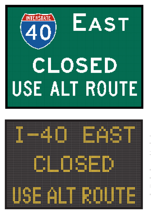
§2L.05 Message Length and Units of Information¶
Guidance
01. The maximum length of a message should be dictated by the number of units of information contained in the message, in addition to the size of the CMS. A unit of information, which is a single answer to a single question that a driver can use to make a decision, should not be more than four words.
Support
02. In order to illustrate the concept of units of information, Table 2L-2 shows an example message that is comprised of four units of information.
03. The maximum allowable number of units of information in a CMS message is based on the principles described in this Section, the current highway operating speed, the legibility characteristics of the CMS, and the lighting conditions.
Table 2L-2. Example of Units of Information
| Question | Answer | Number of Information Units |
|---|---|---|
| What happened? | MAJOR CRASH | 1 |
| Where? | AT EXIT 12 | 1 |
| Who is the advisory for? | Drivers heading TO AUSTIN | 1 |
| What is advised? | USE ROUTE 46 | 1 |
Note: The following two-phase message would have four information units:
| Phase 1 | Phase 2 |
|---|---|
| MAJOR CRASH AT EXIT 12 | USE ROUTE 46 TO AUSTIN |
developed from the four information units shown in this table:
Standard
04. Each message shall consist of no more than two phases. A phase shall consist of no more than three lines of text. Each phase shall be understood by itself, and the meaning of the entire message shall be the same, regardless of the sequence in which the phases are read. Each line of legend shall be centered on the sign. Except for signs located on toll plaza structures or other facilities with a similar booth-lane arrangement, if more than one CMS is visible to road users, then only one sign shall display a sequential message at any given time.
Option
05. A legend on a CMS that replicates a legend on a conventional sign that would not normally be center justified may be left justified or right justified as appropriate, such as a travel time or a variable rate toll display.
Standard
06. Abbreviations displayed on CMS shall comply with the provisions of Section 1D.08.
Guidance
07. When designing and displaying messages on CMS, the following principles should be used:
- A. The minimum time that an individual phase is displayed should be based on 1 second per word or 2 seconds per unit of information, whichever produces a lesser value. The display time for a phase should never be less than 2 seconds.
- B. The maximum cycle time of a two-phase message should be 8 seconds.
- C. The duration between the display of two phases should not exceed 0.3 seconds.
- D. No more than three units of information should be displayed in a message phase.
- E. No more than four units of information should be in a message when the traffic operating speeds are 35 mph or more.
- F. No more than five units of information should be in a message when the traffic operating speeds are less than 35 mph.
- G. Only one unit of information should appear on each line of the CMS.
Support
08. Table 2L-2 provides an example of the number of units of information in a message.
Option
09. A unit of information consisting of more than one word may be displayed on more than one line. An additional CMS at a downstream location may be used for the purpose of allowing the entire message to be read twice.
11. If more than two phases would be needed to display the necessary information, additional CMS may be used to display this information as a series of two distinct, independent messages with a maximum of two phases at each location, in accordance with the provisions of Paragraph 4 of this Section.
Support
Tables 2L-3 and 2L-4 provide examples of message construction for CMS. Each example shows the message content, layout, and phasing for a potential message and an improved message. The improved message for each example has been optimized for recognition, comprehension, and effectiveness.
Table 2L-3. Examples of Message Construction for CMS
| Example | Phase | Potential Message | Improved Message | Comments |
|---|---|---|---|---|
| 1 | 1 2 | EXIT 10 CLOSED USE EXIT 12 | EXIT 10 CLOSED USE EXIT 12 | Diversionary message: Each message phase should convey a complete thought independent of the other message phase. The entire message should also make sense regardless of which phase is read first. |
| 2 | 1 2 | ROADWORK AHEAD CAUTION CAUTION CAUTION | ROAD WORK AHEAD FINES DOUBLE | Advance warning message: Condensing ROAD and WORK into single word is not necessary since sign width will accommodate the conventional 2-word message. A general CAUTION message is not specific enough to be actionable by the road user. Message should not be repeated to fill sign. Phase 2 of the improved message can be eliminated without any loss of meaning to Phase 1. |
| 3 | 1 2 | RIGHT LANE CLOSED 1 MILE | RIGHT LANE CLOSED 1 MILE N/A Single-Phase Message | Advance warning message: Use of single phase message reduces time necessary to read and glances away from the road. Second phase does not provide a complete message. |
| 4 | 1 2 | RT LN CLSD 1 MI N/A Single-Phase Message | RIGHT LANE CLOSED 1 MILE N/A Single-Phase Message | Advance warning message: Less common abbreviations (see Table 1D-2) are not warranted when the sign can accommodate the full message. Abbreviations in Table 1D-2 should be limited only to portable CMS where the number of characters per line is limited. |
| 5 | 1 2 | 9TH AVENUE SOUTHWEST KEEP RIGHT N/A Single-Phase Message | 9TH AVE SW KEEP RIGHT N/A Single-Phase Message | Directional message: Conventional abbreviations for street name descriptors (see Table 2D-3) are used for consistency with standard signs to improve recognition and reduce the apparent amount of legend. |
| 6 | 1 2 | EXPWY CONGESTED USE 101 FOR AIRPORT N/A Single-Phase Message | US 19 CONGESTED AIRPORT USE EXIT 101 | Diversionary message: Lack of Expressway route number is vague to unfamiliar road user. Adding exit number for diversion route simplifies message. Diversion message is stated in reverse order and requires more words as a result. |
| 7 | 1 2 | TRAVEL TIME TO I-89 13 MINUTES TRAVEL TIME TO I-89 12 MILES | I-89 JCT 12 MILES 13 MINS N/A Single-Phase Message | Travel time information: TRAVEL TIME legend is extraneous and out of context for the distance message. Changing only one line of legend between phases compromises recognition of the message. |
| 8 | 1 2 | SEAT BELTS SAVE LIVES N/A Single-Phase Message | STATE LAW FASTEN SEAT BELTS N/A Single-Phase Message | Regulatory message: As an alternative, the STATE LAW legend could be eliminated and the fine for violations displayed on a second phase to convey the regulatory nature of the message. |
Note: Examples shown are for single-color CMS with pixel spacing greater than 20 mm and use all upper-case lettering. Multi-color, full-matrix CMS with pixel spacing of 20 mm or less should use upper- and lower-case lettering where appropriate and proper legend and background colors.
Table 2L-4. Examples of Message Construction for Portable CMS*
| Example | Phase | Potential Message | Improved Message | Comments |
|---|---|---|---|---|
| 1 | 1 2 | EXIT 10 CLOSED USE EXIT 12 | EXIT 10 CLOSED USE EXIT 12 | Diversionary message: Each phase conveys a complete thought. |
| 2 | 1 2 | ROADWORK AHEAD CAUTION CAUTION CAUTION | ROAD WORK AHEAD FINES DOUBLE | Advance warning message: Condensing ROAD and WORK into a single word is unnecessary because the sign width will accommodate the conventional 2-word phrase. A general CAUTION message is not specific enough to be useful to the road user. Message should not be repeated to fill the sign. Phase 2 of the improved message can be eliminated without any loss of meaning to Phase 1. |
| 3 | 1 2 | RIGHT LANE CLOSED 1 MILE | RIGHT LN CLOSED 1 MILE N/A Single-Phase Message | Advance warning message: Separation of the message into 2 phases is unnecessary. Second phase does not provide a complete message. |
| 4 | 1 2 | RT LN CLSD 1 MI N/A Single-Phase Message | RIGHT LN CLOSED 1 MILE N/A Single-Phase Message | Advance warning message: Less common abbreviations (see Table 1D-2) are not warranted when the sign can accommodate the full message. |
| 5 | 1 2 | 9TH AVENUE SW KEEP RIGHT | 9 AVE SW KEEP RIGHT N/A Single-Phase Message | Directional message: Conventional abbreviations for street name descriptors (see Table 2D-3) are used for consistency with standard signs to improve recognition and reduce the apparent amount of legend. |
| 6 | 1 2 | ROAD WORK NEXT 3 MILES | ROADWORK NEXT 3 MILES N/A Single-Phase Message | Advance warning message: Condensing ROAD and WORK into single word (see Table 1D-2) accommodates a single-phase message. |
| 7 | 1 2 | SEAT BELTS SAVE LIVES | FASTEN SEAT BELTS STATE LAW | Regulatory message: Phase 2 of the improved message can be eliminated without any loss of meaning to Phase 1. |
* Examples shown are for a PCMS where the display width is generally limited to 8 characters per line of legend.
§2L.06 Travel Time Messages¶
Support
01. Travel times provide road users useful information about the level of congestion on segments of highways where motorists experience frequent incidents that slow traffic. Travel times are only helpful to the road user if they have a general understanding of the length of the road segment the travel time is related to so that they can compare that to the time it takes them to travel a similar distance on a highway without congestion. However, travel time messages require road users to read and process a significant amount of information and careful consideration is needed to ensure the overall message is not overloading the motorist.
Guidance
02. Travel times should be tied to the distance to a particular destination or junction so that road users can estimate the level of congestion based on the time to travel that distance. When travel times are displayed on CMS, such as during peak traffic conditions, the message should comply with the provisions of Sections 2E.49 and 2E.50. If both a travel time and a distance are displayed, the sign should display only one destination. A distance displayed as part of a travel time message should be rounded to the nearest whole mile.
Option
03. When comparative travel time displays are used providing travel times on different routes to one destination, distances to that destination may be eliminated.
04. A reference-location-based exit number (see Section 2E.22) may be displayed in lieu of a destination name or junction thereby providing the necessary distance information to the road user. If reference-location-based exit numbers are displayed, then up to two travel times may be displayed provided that the distance to the exit is not also displayed.
§2L.07 Traffic Safety Campaign Messages¶
Support
01. An allowable ancillary use of CMS is the display of traffic safety messages in conjunction with a traffic safety campaign that includes other forms of media as the primary communication and education mechanism.
Standard
02. Traffic control messages shall have priority over traffic safety campaign messages.
Guidance
03. When a CMS is used to display a traffic safety campaign, the message should be simple, direct, brief, legible, and clear (see Section 1D.01). Traffic safety campaign messages should be relevant to the road user on the roadway on which the message is displayed. For example, messages regarding school bus stop safety should not be displayed on freeways where school bus stops are not found.
04. A CMS should not be used to display a traffic safety campaign message if doing so could adversely affect respect for the sign. Messages with obscure or secondary meanings, such as those with popular culture references, unconventional sign legend syntax, or that are intended to be humorous, should not be used as they might be misunderstood or understood only by a limited segment of road users and require greater time to process and understand. Similarly, slogan-type messages and the display of statistical information should not be used.
05. The broad traffic safety campaign marketing message should be appropriately shortened or otherwise modified to comply with the provisions of Section 2L.05 when a traffic safety campaign message is displayed on a CMS.
06. Traffic safety campaign messages should emphasize the applicable regulation or warning and should reference any penalties associated with violations of the regulation. Traffic safety campaigns using CMS should include coordinated enforcement efforts where penalties or enforcement type warnings are part of the message displayed on the CMS.
07. Traffic safety campaign messages should not be displayed on CMS unless they are part of an active, coordinated safety campaign that uses other media forms as the primary means of outreach. For consistency on a national level, traffic safety campaigns should be coordinated with those on the National Highway Transportation Safety Administration’s annual communications calendar.
Support
Examples of traffic safety campaign messages include “DRINK DRIVE GO TO JAIL”, “CLICK IT OR TICKET -- FINES UP TO $200,” and “IMPAIRED DRIVERS LOSE LICENSE + JAIL.”
§2L.08 Permanently-Located Changeable Message Signs¶
Support
01. Careful consideration of CMS installation location is important to having a safe and effective message, taking into account several factors. CMS message length and complexity will vary and often include two-phase displays, all of which might require longer glance times by motorists than would be required for conventional sign messages.
02. Permanently-located CMS are generally used on higher-speed, multi-lane facilities with high traffic volumes where more time might be required to properly respond to a message, such as by changing lanes or reducing speed. It also is common for other signs to be in the same vicinity of the desired location for a permanentlylocated CMS raising the concern of overloading road users with information.
Guidance
03. A CMS that is used in place of a conventional sign (such as a blank-out or variable legend regulatory sign) should be located in accordance with the provisions of Chapter 2A and the provisions for the conventional sign it replaces.
04. Permanently-located CMS should:
- A. Be located sufficiently upstream of known bottlenecks and high crash locations to enable road users to select an alternate route or take other appropriate action in response to a recurring condition.
- B. Be located sufficiently upstream of major diversion decision points, such as interchanges, to provide adequate distance over which road users can change lanes to reach one destination or the other.
- C. Not be located within an interchange except for toll plazas or managed lanes.
- D. Not be positioned at locations where the information load on drivers is already high because of guide signs and other types of information.
- E. Not be located in areas where drivers frequently perform lane-changing maneuvers in response to guide sign information, or because of merging or weaving conditions.
Support
05. Many of the factors in locating permanently-located CMS apply to PCMS. Information regarding the design and application of PCMS in temporary traffic control zones is contained in Section 6L.05.
Chapter 2M. RECREATIONAL AND CULTURAL INTEREST AREA SIGNS¶
§2M.01 Scope¶
Support
01. Recreational or cultural interest areas are attractions or traffic generators that are open to the general public for the purpose of play, amusement, or relaxation. Recreational attractions include such facilities as parks, campgrounds, game-hunting facilities, and ski areas, while examples of cultural attractions include museums, art galleries, and historical buildings or sites.
02. The purpose of recreation and cultural interest area signs is to guide road users to a general area and then to specific facilities or activities within the area.
Guidance
03. Recreational and cultural interest area guide signs should not be installed on state roadways unless the traffic generator criteria is met (see Table 2M-1A).
04. If used, recreational and cultural interest area symbol signs (see Table 2M-1) should be installed within the recreational or cultural interest area.
Table 2M-1. Category Chart for Recreational and Cultural Interest Area Symbols
| General | |
|---|---|
| Bear Viewing Area | RS-012 |
| Bus Stop * | RS-031 |
| Campfires * | RS-042 |
| Deer Viewing Area | RS-011 |
| Fire Extinguisher * | RS-090 |
| Lighthouse | RS-007 |
| Lookout Tower | RS-006 |
| Nature Study Area | RS-141 |
| Pick-Up Trucks * | RS-140 |
| Recycling * | RS-200 |
| Sea Plane | RS-115 |
| Smoking* | RS-002 |
| Tunnel * | RS-005 |
| Viewing Area | RS-036 |
| Services | |
|---|---|
| Electrical Hook-Up * | RS-150 |
| First Aid * | RS-024 |
| Laundromat * | RS-085 |
| Picnic Shelter | RS-039 |
| Picnic Site | RS-044 |
| Post Office * | RS-026 |
| Showers * | RS-035 |
| Tramway | RS-071 |
| Trash Dumpster * | RS-091 |
| Water Recreation | |
|---|---|
| Beach | RS-145 |
| Boat Ramp | RS-054 |
| Canoeing | RS-079 |
| Fishing Area | RS-063 |
| Hand Launch/Small Boat Launch * | RS-117 |
| Jet Ski/Personal Watercraft | RS-121 |
| Marina * | RS-053 |
| Motorboating | RS-055 |
| Scuba Diving | RS-060 |
| Seal Viewing | RS-106 |
| Swimming | RS-061 |
| Waterskiing | RS-058 |
| Whale Viewing | RS-107 |
| Land Recreation | |
|---|---|
| All-Terrain Trail | RS-095 |
| Archery | RS-116 |
| Baseball | RS-096 |
| Climbing | RS-082 |
| Golfing | RS-128 |
| Hiking Trail | RS-068 |
| Horse Trail | RS-064 |
| In-Line Skating * | RS-125 |
| Skateboarding * | RS-098 |
| Spelunking/Caves * | RS-084 |
| Technical Rock Climbing * | RS-081 |
| Tennis | RS-129 |
| Wildlife Viewing | RS-076 |
| Accommodations | |
|---|---|
| Men’s Restroom * | RS-021 |
| Parking | RS-034 |
| Recreational Vehicle Site * | RS-104 |
| Restrooms * | RS-022 |
| Sleeping Shelter | RS-037 |
| Trailer Site * | RS-040 |
| Women’s Restroom * | RS-023 |
| Winter Recreation | |
|---|---|
| Chair Lift/Ski Lift | RS-105 |
| Cross Country Skiing | RS-046 |
| Dog Sledding | RS-143 |
| Sledding | RS-049 |
| Snow Tubing | RS-144 |
| Snowshoeing | RS-078 |
| Winter Recreational Area | RS-077 |
*For use only within recreational and cultural interest areas where speed limits are 25 mph or less.
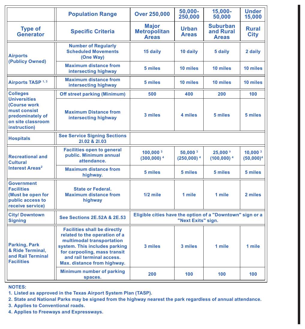
§2M.01A Traffic Generator Criteria¶
Support
01. Normal guide, information, and destination signs are used to inform vehicle operators of a specific route or destination and guide them along the route to their destination. Frequently, a destination which generates a significant volume of traffic that is unfamiliar with the local area, referred to as a traffic generator, is encountered adjacent to or near a highway.
02. It is necessary to establish criteria for determining the traffic generators that warrant consideration to be shown on supplemental guide signs so the generators shown are the ones which best satisfy the information requirements of vehicle operators that are unfamiliar with the area. The criteria limits the number of traffic generator signs installed to minimize confusion that may occur when vehicle operators are faced with an information overload.
05. Established criteria for traffic generator signing provides fair and consistent treatment of requests for signing traffic generators as well as providing uniform signing for similar facilities throughout the State.
Option
To properly serve traffic, it may be desirable to provide supplemental guide signs to direct traffic to such generators so as to improve traffic flow and safety near these traffic generators. The types of traffic generators shown in Table 2M-1A may be considered for signing on Texas highways.
Guidance
A destination should meet the applicable criteria shown in Table 2M-1A to be eligible for a traffic generator sign. To be signed as traffic generator, the qualifying generator should be immediately adjacent to the signed highway or lie on a roadway intersected by the signed highway. If a facility or a private sign for the facility is clearly visible from the roadway, traffic generator signing should not be used.
Standard
06. Facilities shall be open to the general public to be eligible for traffic generator signing.
§2M.02 Application of Recreational and Cultural Interest Area Signs¶
Support
01. Provisions for signing recreational or cultural interest areas are subdivided into two different types of signs: (1) symbol signs and (2) destination guide signs.
Guidance
02. Recreational and cultural interest area destination guide signs should not be installed on facilities that are eligible for tourist-oriented directional signs.
Option
03. Recreational and cultural interest area guide signs may be used in recreational or cultural interest areas for signing non-vehicular events and amenities such as trails, structures, and facilities.
Support
04. Symbols for use only within recreational and cultural interest area facilities are noted in Table 2M-1.
05. Section 2A.09 contains information regarding the use of recreational and cultural interest area symbols on other types of signs.
§2M.03 Regulatory and Warning Signs¶
Standard
01. All regulatory and warning signs installed on roads and streets open to public travel within recreational and cultural interest areas shall comply with the requirements elsewhere in this Manual.
§2M.04 General Design Requirements for Recreational and Cultural Interest Area Symbol Guide Signs¶
Standard
01. When a General Information symbol contained in Chapter 2H (see Figure 2H-1) is used in conjunction with recreational and cultural interest area signing on roadways outside a recreational and cultural interest area facility, the legend and background color of the General Information symbol sign shall be as prescribed in Chapter 2H.
02. When a General Service symbol contained in Chapter 2I (see Figure 2I-1) is used in conjunction with recreational and cultural interest area signing on roadways outside a recreational and cultural interest area facility, the legend and background color of the General Service symbol sign shall be as prescribed in Chapter 2I.
Option
03. For roadways inside a recreational and cultural interest area, General Information symbol signs and General Service symbol signs may have a white legend on a brown background (see Figures 2H-1 and 2I-1).
Standard
04. Except as provided in Section 2M.09, recreational and cultural interest area symbol guide signs shall be square or rectangular in shape and shall have a white symbol or message and white border on a brown background. The symbols shall be grouped into the following usage and series categories:
- A. General Applications,
- B. Accommodations,
- C. Services,
- D. Land Recreation,
- E. Water Recreation, and
- F. Winter Recreation.
Support
05. Table 2M-1 contains a listing of the symbols within each series category.
Option
06. Mirror images of symbols may be used where the reverse image will better convey the message (see Section 2A.09).
§2M.05 Symbol Sign Sizes¶
Guidance
01. Recreational and cultural interest area symbol signs should be 24 x 24 inches. Where greater visibility or emphasis is needed, larger sizes should be used. Symbol sign enlargements should be in 6-inch increments.
02. Recreational and cultural interest area symbol signs should not be used on guide signs on freeways or expressways.
Option
03. A smaller size of 18 x 18 inches may be used on low-speed, low-volume roadways and on non-road applications.
§2M.06 Use of Educational Plaques¶
Guidance
01. Educational plaques should accompany all initial installations of recreational and cultural interest area symbol signs. If used, the educational plaque should be the same width as the symbol sign.
Option
02. Symbol signs that are readily recognizable by the public may be installed without educational plaques.
Support
03. Figure 2M-1 illustrates some examples of the use of educational plaques.
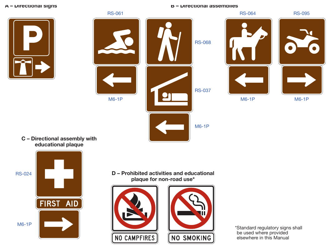
Signs shown: M6-1P
§2M.07 Use of Prohibitive Circle and Diagonal for Non-Road Applications¶
Standard
01. Where it is necessary to indicate a prohibition of an activity or an item within a recreational or cultural interest area for non-road use and a standard regulatory sign for such a prohibition is not provided in Chapter 2B, the appropriate recreational and cultural interest area symbol shall be used in combination with a red prohibitive circle and diagonal. The recreational and cultural interest area symbol and the sign border shall be black and the sign background shall be white. The symbol shall be scaled proportionally to fit completely within the circle. The diagonal shall be oriented from the upper left to the lower right portions of the circle as shown in Figure 2M-1 and as detailed in the “Standard Highway Sign Designs for Texas” publication.
02. Requirements for retroreflection of the red circle and diagonal shall be the same as those requirements for backgrounds, legends, symbols, arrows, and borders.
§2M.08 Placement of Recreational and Cultural Interest Area Symbol Signs¶
Standard
01. If used, recreational and cultural interest area symbol signs shall be placed in accordance with the general requirements contained in Chapter 2A. The symbol(s) shall be placed as sign panels in the uppermost part of the sign and the directional information shall be placed below the symbol(s).
02. If the name of the recreational or cultural interest area facility or activity is displayed on a destination guide sign (see Section 2M.09) and a symbol is used, the symbol shall be placed below the name (see Figure 2M-2).
Option
03. The symbols displayed with the facility or activity name may be placed below the destination guide sign as illustrated in Figure 2M-2 instead of as sign panels placed with the destination guide sign.
04. Secondary symbols of a smaller size (18 x 18 inches) may be placed beneath the primary symbols (see Drawing A in Figure 2M-1), where needed.
Standard
05. Recreational and cultural interest area symbols installed for non-road use shall be placed in accordance with the general sign position requirements of the authority having jurisdiction.
Support
06. Figure 2M-3 illustrates typical height and lateral mounting positions. Figure 2M-4 illustrates some examples of the placement of symbol signs within a recreational or cultural interest area. Figures 2M-5 through 2M-10 illustrate some of the symbols that can be used.
Guidance
07. The number of symbols used in a single sign assembly should not exceed four.
Option
08. The Advance Turn (M5 series) or Directional Arrow (M6 series) auxiliary signs (see Figure 2D-6) with white arrows on brown backgrounds may be used with recreational and cultural interest area symbol guide signs to create a recreational and cultural interest area directional assembly. The symbols may be used singularly, or in groups of two, three, or four on a single sign assembly (see Figures 2M-1, 2M-3, and 2M-4).
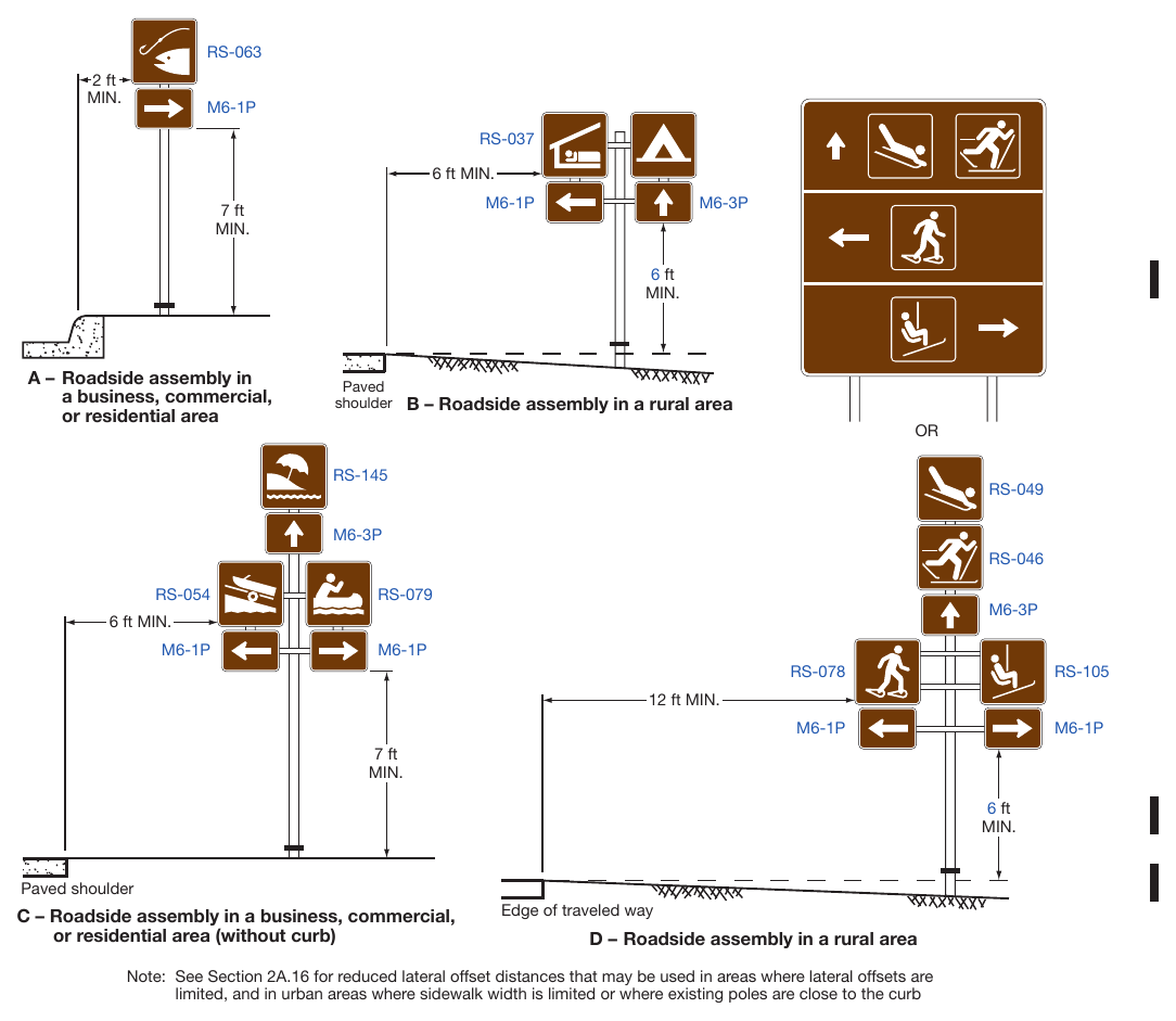
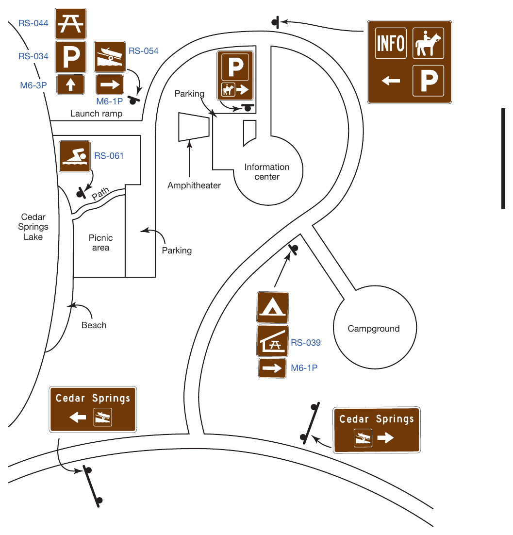
§2M.09 Destination Guide Signs¶
Standard
01. When recreational or cultural interest area destinations are displayed on a Supplemental guide sign (see Section 2E.51), the sign shall be rectangular in shape with a white legend on a green or brown background.
Option
02. Destination guide signs with a white legend and border on a brown background may be posted at the first point where an access or crossroad intersects a highway where recreational or cultural interest areas are a significant destination along conventional roads, expressways, or freeways. Supplemental guide signs with a white legend and border on a brown background may be used along conventional roads, expressways, or freeways to direct road users to recreational or cultural interest areas. Where access or crossroads lead exclusively to the recreational or cultural interest area, the Advance guide sign (see Section 2E.23) and the Exit Direction sign (see Section 2E.25) may have a white legend and border on a brown background.
Standard
03. All Exit Gore (E5-1 series) signs (see Section 2E.26) shall have a white legend and border on a green background. The background color of the interchange Exit Number (E1-5P or E1-5bP) plaque (see Section 2E.22) shall match the background color of the guide sign above which it is mounted. Design characteristics of conventional road, expressway, or freeway guide signs shall comply with Chapter 2D or 2E except as provided in this Section for color combination.
04. The Advance guide sign and the Exit Direction sign shall retain the white-on-green color combination where the crossroad also leads to a destination other than a recreational or cultural interest area.
Support
07. Figure 2M-2 illustrates destination guide signs commonly used for identifying recreational or cultural interest areas or facilities.
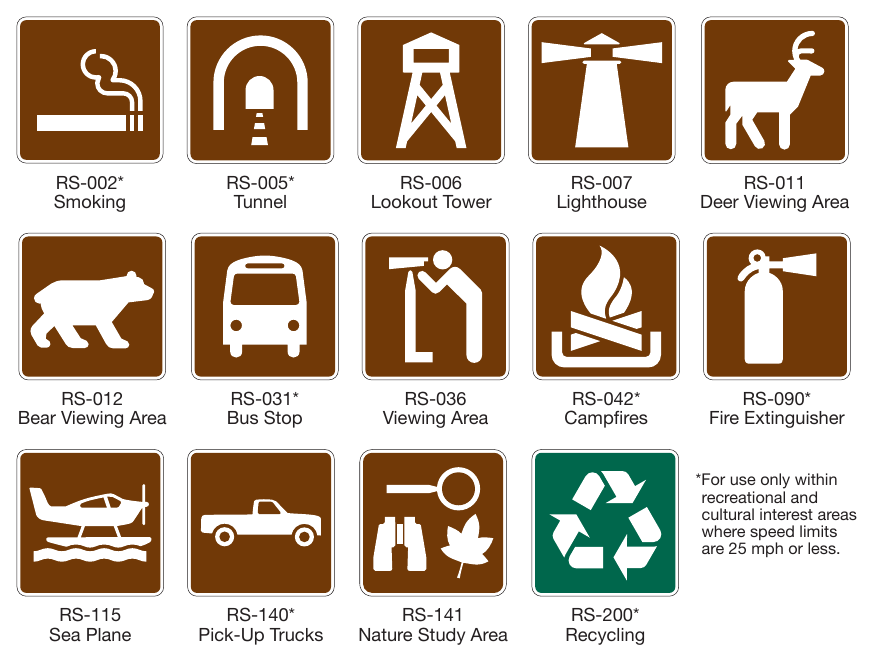
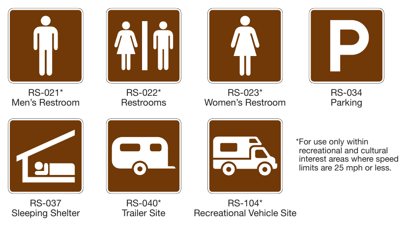
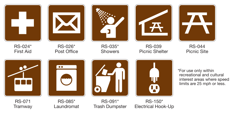
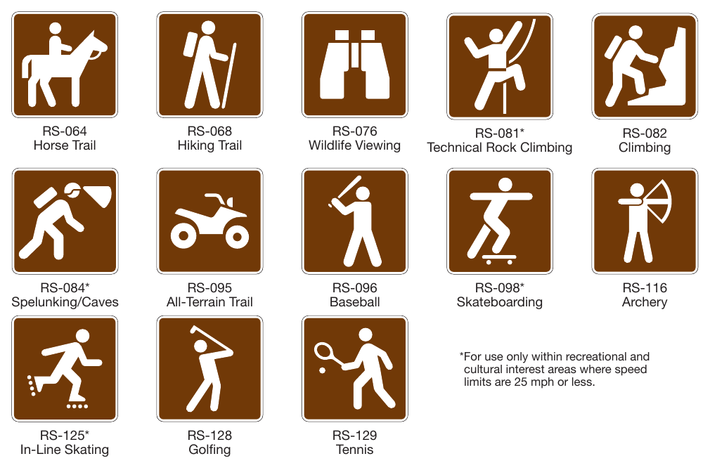
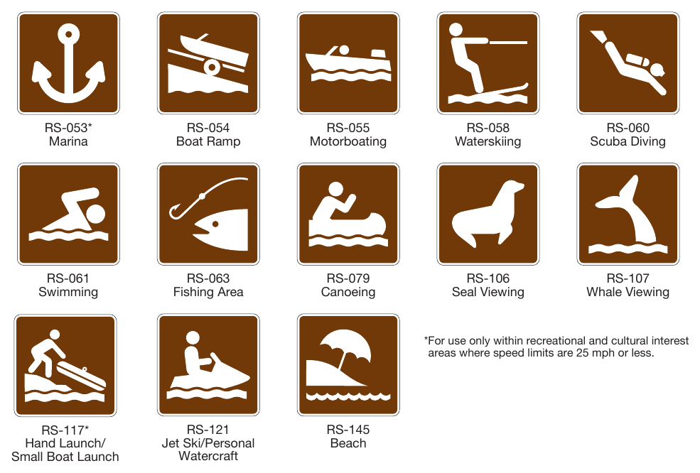
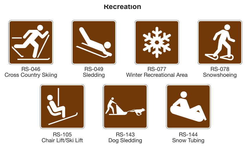
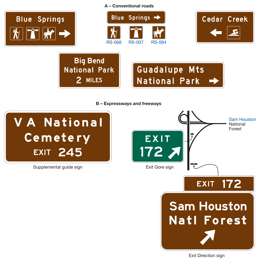
§2M.10 Memorial or Dedication Signing¶
Support
01. Legislative bodies will occasionally adopt an act or resolution memorializing or dedicating a highway, bridge, or other component of the highway.
02. Named highways (see Section 2D.56) are officially designated and shown on official maps and serve the purpose of providing route guidance, primarily on unnumbered highways, and property addresses. A highway designated as a memorial or dedication is not considered to be a named highway for the purposes of highway signing or road user navigation and orientation.
03. Section 2A.20 contains information regarding excessive use of signs. Because memorial or dedication names are not official highway names, memorial and dedication signing is not essential to providing navigational guidance.
Guidance
04. Such memorial or dedication names should not appear on or along a highway, or be placed on bridges or other highway components. If a route, bridge, or highway component is officially designated as a memorial or dedication, and if notification of the memorial or dedication is to be made on the highway right-of-way, such notification should consist of installing a memorial or dedication marker in a rest area, scenic overlook, recreational area, or other appropriate location where parking is provided with the signing inconspicuously located relative to vehicle operations along the highway.
05. Memorial or dedication signs should have a white legend and border on a brown background. On all such signs, the design should be simple and dignified, devoid of any appearance of advertising, and in general compliance with other signing.
06. The lettering for the name of the person or entity being recognized should be composed of a combination of lower-case letters with initial upper-case letters.
Standard
07. Where such memorial or dedication signs are installed on the highway mainline because the provisions of Paragraph 4 of this Section cannot be met, (1) memorial or dedication names shall not appear on directional guide signs, (2) memorial or dedication signs shall not interfere with the placement of any other traffic control devices, and (3) memorial or dedication signs shall not compromise the safety or efficiency of traffic flow. The memorial or dedication signing shall be limited to one sign at an appropriate location in each route direction, each as an independent post-mounted sign installation.
08. Memorial or dedication signs shall be rectangular in shape. The legend displayed on memorial or dedication signs shall be limited to the name of the person or entity being recognized and a simple message preceding the name, such as “DEDICATED TO.” Additional legend, such as biographical information, shall not be displayed on memorial or dedication signs. Decorative or graphical elements, pictographs, logos, or symbols shall not be displayed on memorial or dedication signs. All letters and numerals displayed on memorial or dedication signs shall be as provided in the “Standard Highway Sign Designs for Texas” publication (see Section 1A.05). The route number or officially mapped name of the highway shall not be displayed on the memorial or dedication sign.
09. Memorial or dedication signs shall not imply that a highway has been officially renamed.
10. Memorial or dedication names shall not appear on supplemental signs or on any other information sign on or along the highway or its intersecting routes.
Guidance
11. Freeways and expressways should not be signed as memorial or dedicated highways.
12. When used, memorial or dedication signs should be located in accordance with the provisions for excessive use of signs (see Section 2A.20).
Support
13. Paragraph 36 of Section 2D.45 contains provisions regarding the use of memorial or dedication signing in conjunction with Street Name signs.
§2M.10A Historical Marker Guide Signs¶
Support
01. Historical marker guide (D7-6aT and D7-7aT) signs (see Figure 2M-10A) are used to provide advance and directional guidance for official historical marker locations, as designated by the Texas Historical Commission.
Guidance
02. The design of the historical marker guide sign should be as shown in the “Standard Highway Sign Designs for Texas” publication (see Section 1A.05).
Support
03. As part of a statewide identification and reference system, the Texas Historical Commission has assigned numbers to all historical markers, referred to as Atlas numbers.
Guidance
04. The Atlas number should be displayed in conjunction with the historical marker advance and directional guide signs (see Figure 2M-10A).
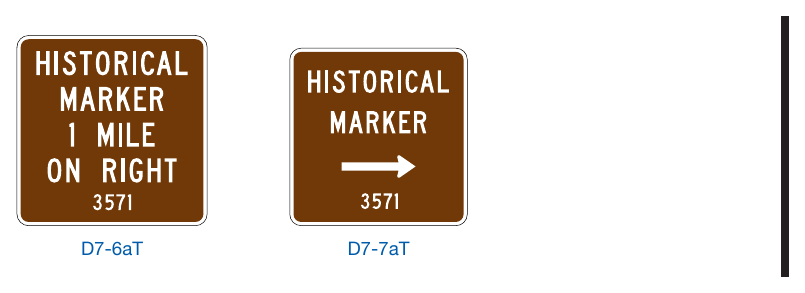
Signs shown: D7-6aT, D7-7aT
Chapter 2N. EMERGENCY MANAGEMENT SIGNS¶
§2N.01 Emergency Management¶
Guidance
01. Contingency planning for an emergency evacuation should be considered by all State and local jurisdictions and should consider the use of all applicable roadways.
02. In the event of a disaster where highways that cannot be used will be closed, a successful contingency plan should account for the following elements: a controlled operation of certain designated highways, the establishment of traffic operations for the expediting of essential traffic, and the provision of emergency centers for civilian aid.
§2N.02 Design and Use of Emergency Management Signs¶
Standard
01. Emergency Management signs (see Figure 2N-1) shall be used to guide and control highway traffic during an emergency.
Guidance
02. During an emergency, permanently-installed regulatory and warning signs that conflict with Emergency Management signs should be removed or covered until such time as the Emergency Management signs are no longer necessary.
03. Except for Evacuation Route signs, Emergency Management signs that are no longer necessitated by the emergency should be promptly removed and signs that normally provide regulation, warning, or guidance that were removed or covered during the emergency should be promptly displayed again.
Standard
04. Advance planning for transportation operations emergencies shall be the responsibility of State and local authorities.
Support
05. The Federal Government provides guidance to the States as necessitated by changing circumstances.
Standard
06. Except as provided in Section 2A.07, the sizes for Emergency Management signs shall be as shown in Table 2N-1.
Support
07. Section 2A.07 contains information regarding the applicability of the various columns in Table 2N-1.
Option
08. Signs larger than those shown in Table 2N-1 may be used (see Section 2A.07).
Guidance
09. As conditions permit, the Emergency Management signs should be replaced or augmented by standard signs.
10. Except where specifically required elsewhere in this Chapter, the background of Emergency Management signs should be retroreflective.
11. Because Emergency Management signs might be needed in large numbers for temporary use during an emergency, consideration should be given to their fabrication from any light and economical material that can serve through the emergency period.
Option
12. Any Emergency Management sign that is used to mark an area that is contaminated by biological or chemical warfare agents or radioactive fallout may be accompanied by the standard symbol that is illustrated in the upper left corner of the EM4-1b and EM4-1c signs in Figure 2N-1.
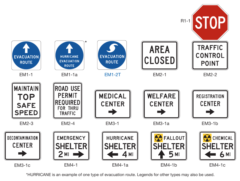
Signs shown: R1-1, EM1-1, EM1-1a, EM1-2T, EM2-1, EM2-2, EM2-3, EM2-4, EM3-1, EM3-1a, EM3-1b, EM3-1c, EM4-1, EM4-1a, EM4-1b, EM4-1c
Table 2N-1. Emergency Management Sign Sizes
| Sign or Plaque | Sign Designation | Section | Minimum Size |
|---|---|---|---|
| Evacuation Route | EM1-1, EM-1a, EM1-2T | 2N.03 | 24 x 24 |
| Area Closed | EM2-1 | 2N.04 | 30 x 24 |
| Traffic Control Point | EM2-2 | 2N.05 | 30 x 24 |
| Maintain Top Safe Speed | EM2-3 | 2N.06 | 24 x 30 |
| Permit Required | EM2-4 | 2N.07 | 24 x 30 |
| Emergency Aid Center | EM3-1, EM3-1a, EM3-1b, EM3-1c | 2N.08 | 30 x 24 |
| Shelter Directional | EM4-1, EM4-1a, EM4-1b, EM4-1c | 2N.09 | 30 x 24 |
Notes: 1. Larger signs may be used when appropriate 2. Dimensions are shown as width x height, in inches
§2N.03 Evacuation Route Signs (EM1 Series)¶
Standard
01. An Advance Turn Arrow (M5 series) or Directional Arrow (M6 series) auxiliary plaque (see Figure 2D-6) shall be installed below the EM1-2T sign. The Advance Turn Arrow or Directional Arrow auxiliary plaque shall have a white arrow and border on a blue background when used with an EM1-2T sign.
Option
02. Where different evacuation conditions use different evacuation routes in the same area, the word HURRICANE, or a word that describes some other type of evacuation route, may be added above the EVACUATION ROUTE legend within the blue circular symbol on the EM1-1a sign.
Standard
03. The EM1-1 series signs shall include a white directional arrow. The arrow designs on the EM1-1 series signs shall include a straight, vertical arrow pointing upward, a straight horizontal arrow pointing to the left or right, or a bent arrow pointing to the left or right for advance warning of a turn.
Guidance
04. If used, the Evacuation Route sign, with the appropriate arrow, should be installed 150 to 300 feet in advance of, and at, any turn in an approved evacuation route. The sign should also be installed elsewhere for straight-ahead confirmation where needed.
Standard
05. If used in urban areas, the Evacuation Route sign shall be mounted at the right-hand side of the roadway, not less than 7 feet above the top of the curb, and at least 1 foot back from the face of the curb. If used in rural areas, the Evacuation Route sign shall be mounted at the right-hand side of the roadway, not less than 7 feet above the near edge of the pavement and not less than 6 feet or more than 10 feet to the right of the right-hand roadway edge.
06. Evacuation Route signs shall not be placed where they will conflict with other signs. Where a conflict in placement would occur between the Evacuation Route sign and a standard regulatory sign, the regulatory sign shall take precedence.
Option
07. In case of a conflict with guide or warning signs, the Evacuation Route sign may take precedence.
Guidance
08. Placement of Evacuation Route signs should be made under the supervision of the officials having jurisdiction over the placement of other traffic signs. Coordination with Emergency Management authorities and agreement between contiguous political entities should occur to assure continuity of routes.
09. Use of the specific Evacuation Route (EM1-1a and EM1-2T) signs should be limited to areas where different evacuation conditions use different evacuation routes.
§2N.04 AREA CLOSED Sign (EM2-1)¶
Guidance
01. The AREA CLOSED (EM2-1) sign (see Figure 2N-1) should be used to close a roadway in order to prohibit traffic from entering the area. It should be installed on the shoulder as near as practical to the right-hand edge of the roadway, or preferably, on a portable mounting or barricade partly or entirely in the roadway.
02. For best visibility, particularly at night, the sign height should not exceed 4 feet measured vertically from the pavement to the bottom of the sign. Unless adequate advance warning signs are used, it should not be placed to create a complete and unavoidable blocked route. Where feasible, the sign should be located at an intersection that provides a detour route.
§2N.05 TRAFFIC CONTROL POINT Sign (EM2-2)¶
Guidance
01. The TRAFFIC CONTROL POINT (EM2-2) sign (see Figure 2N-1) should be used to designate a location where an official traffic control point has been set up to impose such controls as are necessary to limit congestion, expedite emergency traffic, exclude unauthorized vehicles, or protect the public.
02. The sign should be installed in the same manner as the AREA CLOSED sign (see Section 2N.04), and at the point where traffic must stop to be checked.
03. A STOP (R1-1) sign (see Section 2B.04) should be used in conjunction with the TRAFFIC CONTROL POINT sign.
04. The TRAFFIC CONTROL POINT sign should be mounted directly below the STOP sign.
§2N.06 MAINTAIN TOP SAFE SPEED Sign (EM2-3)¶
Option
01. The MAINTAIN TOP SAFE SPEED (EM2-3) sign (see Figure 2N-1) may be used on highways where conditions are such that it is prudent to evacuate or traverse an area as quickly as possible.
02. Where an existing Speed Limit (R2-1) sign is in a suitable location, the MAINTAIN TOP SAFE SPEED sign may be mounted directly over the face of the speed limit sign that it supersedes.
Support
03. Since any speed zoning would be impractical under such emergency conditions, no minimum speed limit can be prescribed by the MAINTAIN TOP SAFE SPEED sign in numerical terms. Where traffic is supervised by a traffic control point, official instructions will usually be given verbally, and the sign will serve as an occasional reminder of the urgent need for maintaining the proper speed.
Guidance
04. The sign should be installed as needed, in the same manner as other standard speed signs.
Standard
05. If used in rural areas, the MAINTAIN TOP SAFE SPEED sign shall be mounted on the right-hand side of the road at a horizontal distance of not less than 6 feet or more than 10 feet from the roadway edge, and at a minimum height, measured vertically from the bottom of the sign to the elevation of the near edge of the traveled way, of 7 feet. If used in urban areas, the minimum height, measured vertically from the bottom of the sign to the top of the curb, or in the absence of curb, measured vertically from the bottom of the sign to the elevation of the near edge of the traveled way, shall be 7 feet, and the nearest edge of the sign shall be not less than 1 foot back from the face of the curb.
§2N.07 Permit Required Sign (EM2-4)¶
Support
01. The intent of the Permit Required (EM2-4) sign (see Figure 2N-1) is to notify road users of the presence of the traffic control point so that those who do not have priority permits issued by designated authorities can take another route, or turn back, without making a needless trip and without adding to the screening load at the post. Local traffic, without permits, can proceed as far as the traffic control post.
Standard
02. If used, the Permit Required (EM2-4) sign shall be used at an intersection that is an entrance to a route on which a traffic control point is located.
03. If used, the EM2-4 sign shall be installed in a manner similar to that of the MAINTAIN TOP SAFE SPEED sign (see Section 2N.06).
§2N.08 Emergency Aid Center Signs (EM3-1 Series)¶
Standard
01. In the event of emergency, State and local authorities shall establish various centers for civilian relief, communication, medical service, and similar purposes. To guide the public to such centers a series of directional signs shall be used.
02. Emergency Aid Center (EM3-1 series) signs (see Figure 2N-1) shall display the designation of the center and an arrow indicating the direction to the center. They shall be installed as needed, at intersections and elsewhere, on the right-hand side of the roadway, in urban areas at a minimum height, measured vertically from the bottom of the sign to the top of the curb, or in the absence of curb, measured vertically from the bottom of the sign to the elevation of the near edge of the traveled way, of 7 feet, and not less than 1 foot back from the face of the curb, and in rural areas at a minimum height, measured vertically from the bottom of the sign to the elevation of the near edge of the traveled way, of 7 feet, and at a horizontal distance of not less than 6 feet or more than 10 feet from the roadway edge.
03. Emergency Aid Center signs shall display one of the following legends, as appropriate, or others designating similar emergency facilities:
- A. MEDICAL CENTER (EM3-1),
- B. WELFARE CENTER (EM3-1a),
- C. REGISTRATION CENTER (EM3-1b), or
- D. DECONTAMINATION CENTER (EM3-1c).
04. The Emergency Aid Center sign shall be a horizontally-oriented rectangle. Except as provided in Paragraph 5 of this Section, the Emergency Aid Center signs shall have a black legend and border on a white background.
Option
05. When Emergency Aid Center signs are used in an incident situation, such as during the aftermath of a nuclear or biological attack, the background color may be fluorescent pink (see Chapter 6O).
§2N.09 Shelter Directional Signs (EM4-1 Series)¶
Standard
01. Shelter Directional (EM4-1 series) signs (see Figure 2N-1) shall be used to direct the public to selected shelters that have been licensed and marked for emergency use.
02. The installation of Shelter Directional signs shall comply with established signing standards. Where used, the signs shall not be installed in competition with other necessary highway regulatory, guide, and warning signs.
03. The Shelter Directional sign shall be a horizontally-oriented rectangle. Except as provided in Paragraph 4 of this Section, the Shelter Directional signs shall have a black legend and border on a white background.
Option
04. When Shelter Directional signs are used in an incident situation, such as during the aftermath of a nuclear or biological attack, the background color may be fluorescent pink (see Chapter 6O).
05. The distance to the shelter may be omitted from the sign when appropriate.
06. Shelter Directional signs may display one of the following legends, or others designating similar emergency facilities:
07. If appropriate, the name of the facility may be used.
08. The Shelter Directional signs may be installed on the Interstate Highway System or any other major highway system when it has been determined that a need exists for such signs as part of a State or local shelter plan.
09. The Shelter Directional signs may be used to identify different routes to a shelter to provide for rapid movement of large numbers of persons.
Guidance
10. The Shelter Directional sign should be used sparingly and only in conjunction with approved plans of State and local authorities.
11. The Shelter Directional sign should not be posted more than 5 miles from a shelter.