Chapter 3G. Delineators¶
§3G.01 General¶
Support
01. Delineators are particularly beneficial at locations where the alignment might be confusing or unexpected, such as at lane-reduction transitions and curves. Delineators are effective guidance devices at night and during adverse weather. An important advantage of delineators in certain locations is that they remain visible when the roadway is wet or covered by snow.
02. Delineators are considered guidance devices to help road users navigate the roadway alignment, rather than warning devices.
Option
03. Delineators may be used on long continuous sections of highway or through short stretches where there are changes in horizontal alignment.
§3G.02 Design¶
Standard
01. Delineators shall consist of retroreflective devices that are capable of clearly retroreflecting light under normal atmospheric conditions from a distance of 1,000 feet when illuminated by the high beams of standard automobile lights. They shall be mounted on crashworthy (see definition in Section 1C.02) supports.
02. Retroreflective elements for delineators shall have a minimum vertical and horizontal dimension of 3 inches, or a minimum diameter dimension of 3 inches when circular.
Support
03. Within a series of delineators along a roadway, delineators for a given direction of travel at a specific location are referred to as single delineators if they have one retroreflective element for that direction, double delineators if they have two identical retroreflective elements for that direction mounted together, or vertically-elongated delineators if they have a single retroreflective element with an elongated vertical dimension to approximate the vertical dimension of two separate single delineators.
Option
04. A vertically-elongated delineator of appropriate size may be used in place of a double delineator.
§3G.03 Application¶
Standard
01. The color of delineators shall comply with the color of edge lines stipulated in Sections 3A.03 and 3B.09.
02. A series of single delineators shall be provided on the right-hand side of freeways and expressways and on at least one side of interchange ramps, except when either Condition A or Condition B is met, as follows:
- A. On tangent sections of freeways and expressways when both of the following conditions are met:
- 1. Raised pavement markers are used continuously on lane lines throughout all curves and on all tangents as described in Section 3B.14, and
- 2. Roadside delineators are used to lead into all curves, or
- B. On sections of roadways where continuous lighting is in operation between interchanges.
Option
03. Delineators may be provided on other classes of roads.
04. A series of single delineators may be provided on the left-hand side of roadways.
05. Chevron Alignment (W1-8) signs may be used instead of or in addition to standard delineators, as provided in Section 2C.08.
Standard
06. Delineators on the left-hand side of a two-way roadway shall be white (see Figure 3G-1).
Guidance
07. A series of single delineators should be provided on the outside of curves on interchange ramps.
08. Where median crossovers are provided for official or emergency use on divided highways and where these crossovers are to be marked with pavement markings, a double yellow delineator should be placed on the left-hand side of the through roadway on the far side of the crossover for each roadway. Double or vertically-elongated delineators should be installed at approximately 100-foot intervals along acceleration and deceleration lanes.
10. A series of delineators should be used wherever guardrail or other longitudinal barriers are present along a roadway or ramp.
Option
11. Red delineators may be used on the reverse side of any delineator where it would be viewed by a road user traveling in the wrong direction on that particular ramp or roadway.
Guidance
12. Except as provided in Paragraph 13 of Section 3B.12, delineators of the appropriate color should be used to indicate a lane-reduction transition where either an outside or inside lane merges into an adjacent lane.
13. When used for lane-reduction transitions, the delineators should be installed adjacent to the lane or lanes reduced for the full length of the transition and should be so placed and spaced to show the reduction (see Section 3B.12 and Figure 3B-14).
14. On a highway with continuous delineation on either or both sides, delineators should be carried through transitions.
Standard
15. When used on a truck escape ramp, delineators shall be red.
Guidance
16. Red delineators should be placed on both sides of truck escape ramps.
§3G.04 Placement and Spacing¶
Guidance
01. Except as provided in Paragraph 2 of this Section, delineators should be mounted at a height, measured vertically from the bottom of the lowest retroreflective device to the elevation of the near edge of the roadway, of approximately 4 feet.
Option
02. When mounted on the face of or on top of guardrails or other longitudinal barriers, delineators may be mounted at a lower elevation than the normal delineator height recommended in Paragraph 1 of this Section.
Guidance
03. Delineators should be placed 2 to 8 feet outside the outer edge of the shoulder, or if appropriate, in line with the roadside barrier that is 8 feet or less outside the outer edge of the shoulder.
04. Delineators should be placed at a constant distance from the edge of the roadway, except that where an obstruction intrudes into the space between the pavement edge and the extension of the line of the delineators, the delineators should be transitioned to be in line with or inside the innermost edge of the obstruction. If the obstruction is a guardrail or other longitudinal barrier, the delineators should be transitioned to be just behind, directly above (in line with), or on the innermost edge of the guardrail or longitudinal barrier.
05. Delineators should not present a vertical or horizontal clearance obstacle for pedestrians.
06. Delineators should be spaced 200 to 530 feet apart on mainline tangent sections. Delineators should be spaced 100 feet apart on ramp tangent sections.
Option
07. On a highway with continuous delineation on either or both sides, the spacing between a series of delineators may be closer.
08. When uniform spacing is interrupted by such features as driveways and intersections, delineators which would ordinarily be located within the features may be relocated in either direction for a distance not exceeding ¼ of the uniform spacing. Delineators still falling within such features may be eliminated.
09. Delineators may be transitioned in advance of a lane transition or obstruction as a guide for oncoming traffic.
Guidance
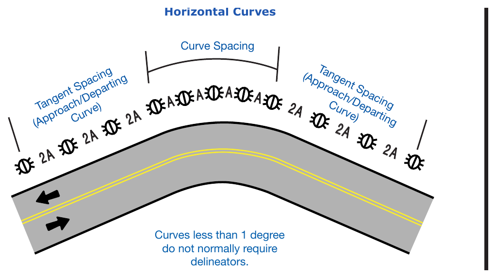
10. The spacing of delineators should be adjusted on approaches to and throughout horizontal curves so that several delineators are always simultaneously visible to the road user. The approximate spacing shown in Table 3G-1 and Figure 3G-1A should be used.
11. The spacing between red delineators that are placed on both sides of a truck escape ramp should not exceed 50 feet for a distance that is sufficient to identify the ramp entrance. The spacing between red delineators that are placed beyond the ramp entrance should be such that adequate guidance is provided based on the length and design of the escape ramp.
Option
12. When needed for special conditions, delineators of the appropriate color may be mounted in a closely-spaced manner on the face of or on top of guardrails or other longitudinal barriers to form a continuous or nearly continuous “ribbon” of delineation.
Support
13. Examples of delineator installations are shown in Figure 3G-1.
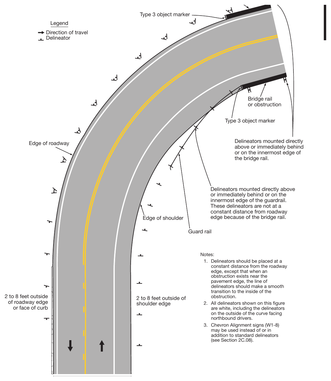
Table 3G-1. Approximate Spacing for Delineators on Horizontal Curves
| Advisory Speed (MPH) | Spacing in Curve (Feet) | Spacing in Tangents (Feet) |
|---|---|---|
| A | 2A | |
| 65 | 130 | 260 |
| 60 | 110 | 220 |
| 55 | 100 | 200 |
| 50 | 85 | 170 |
| 45 | 75 | 150 |
| 40 | 70 | 140 |
| 35 | 60 | 120 |
| 30 | 55 | 110 |
| 25 | 50 | 100 |
| 20 | 40 | 80 |
| 15 | 35 | 70 |
| Degree of Curve | Feet | ||
|---|---|---|---|
| Radius of Curve | Spacing in Curve | Spacing in Tangents | |
| A | 2A | ||
| 1 | 5730 | 225 | 450 |
| 2 | 2865 | 160 | 320 |
| 3 | 1910 | 130 | 260 |
| 4 | 1433 | 110 | 220 |
| 5 | 1146 | 100 | 200 |
| 6 | 955 | 90 | 180 |
| 7 | 819 | 85 | 170 |
| 8 | 716 | 75 | 150 |
| 9 | 637 | 75 | 150 |
| 10 | 573 | 70 | 140 |
| 11 | 521 | 65 | 130 |
| 12 | 478 | 60 | 120 |
| 13 | 441 | 60 | 120 |
| 14 | 409 | 55 | 110 |
| 15 | 382 | 55 | 110 |
| 16 | 358 | 55 | 110 |
| 19 | 302 | 50 | 100 |
| 23 | 249 | 40 | 80 |
| 29 | 198 | 35 | 70 |
| 38 | 151 | 30 | 60 |
| 57 | 101 | 20 | 40 |