2C. Warning Signs and Object Markers¶
§2C.01 Application of Warning Signs¶
Standard
01. The use of warning signs shall be based on an engineering study or on engineering judgment.
02. Warning signs shall be retroreflective or illuminated (see Section 2A.21).
Guidance
03. The use of warning signs should be kept to a minimum as the unnecessary use of warning signs tends to breed disrespect for all signs. In situations where the condition or activity is seasonal or temporary, the warning sign should be removed or covered when the condition or activity does not exist.
§2C.02 Design of Warning Signs¶
Standard
01. Except as provided in Paragraph 2 of this Section or unless specifically designated otherwise, all warning signs shall be diamond-shaped (square with one diagonal vertical) with a black legend and border on a yellow background. Warning signs shall be designed in accordance with the sizes, shapes, colors, and legends contained in the “Standard Highway Signs” publication (see Section 1A.05) and Caltrans’ California Sign Specifications.
Option
02. A warning sign that is larger than the size shown in the Oversized column in Table 2C-1 and 2C-1(CA) for that particular sign may be diamond-shaped or may be rectangular or square in shape.
Support
03. The use of a shape other than diamond-shaped is typical for overhead installations.
04. Section 2A.05 contains information on allowable methods to accommodate a diamond-shaped warning sign where the lateral space available in which to install a diamond-shaped warning sign is constrained, such as in urban locations, when mounting on a narrow median barrier or adjacent to a retaining wall, including the display of the standard legend in a vertically oriented rectangle.
05. The use of LEDs in the border and legend of warning signs is described in Section 2A.12.
Option
06. Except for symbols on warning signs, minor modifications may be made to the design provided that the essential appearance characteristics are met. Modifications may be made to the symbols shown on combined horizontal alignment/intersection signs (see Section 2C.09) and intersection warning signs (see Section 2C.41) in order to approximate the geometric configuration of the intersecting roadway(s).
07. Word message warning signs other than those provided in this Manual may be developed by Caltrans (in accordance with CVC § 21400) and installed by State and/or local highway agencies for conditions otherwise not addressed by standard signs (see Section 2A.04).
08. Warning signs regarding conditions associated with pedestrians, bicyclists, and playgrounds and their related plaques may have a black legend and border on a yellow or fluorescent yellow-green background.
Standard
09. Warning signs regarding conditions associated with school buses and schools and their related supplemental plaques shall have a black legend and border on a fluorescent yellow-green background (see Section 7B.01).
Option
10. Consistent with the provisions of Section 4S.03, a Warning Beacon may be used in combination with a standard warning sign.
Support
11. Refer to Section 2A.09 for the use of educational plaques.
§2C.03 Size of Warning Signs and Plaques¶
Standard
Except as provided in Section 2A.07, the sizes for warning signs shall be as shown in Table 2C-1 and Table 2C-1(CA).
Support
Refer to Paragraph 02 of Section 2C.02 and Paragraph 06 of this section for sizes larger than shown in Table 2C-1 and Table
02. Section 2A.07 contains information regarding the applicability of the various columns in Table 2C-1.
Standard
03. Except as provided in Paragraph 5 of this Section, the minimum size for all diamond-shaped warning signs facing traffic on a multi-lane conventional road where the posted speed limit is higher than 35 mph shall be 36 x 36 inches.
04. The minimum size for supplemental warning plaques that are not included in Table 2C-1 shall be as shown in Table 2C-2.
Option
05. If a diamond-shaped warning sign is placed on the left-hand side of a multi-lane roadway to supplement the installation of the same warning sign on the right-hand side of the roadway, the minimum size identified in the Single Lane column in Table 2C-1 may be used.
06. Signs and plaques larger than those shown in Tables 2C-1 and 2C-2 may be used (see Section 2A.11).
Guidance
07. The minimum size for all diamond-shaped warning signs facing traffic on exit and entrance ramps at major interchanges connecting an Expressway or Freeway with an Expressway or Freeway (see Section 2E.11) should be the size identified in Table 2C-1 for the mainline roadway classification (Expressway or Freeway). If a minimum size is not provided in the Freeway Column, the Expressway size should be used. If a minimum size is not provided in the Freeway or the Expressway Column, the Oversized size should be used.
08. The minimum size for all diamond-shaped warning signs facing traffic on exit and entrance ramps at all other interchanges (see Section 2E.11) should be 36 x 36 inches.
09. The typical size of warning signs used on low-volume rural roads with operating speeds posted speed limits of 30 mph or less should be in accordance with the minimum column of Table 2C-1.
§2C.04 Placement of Warning Signs¶
Support
01. Information on the placement of warning signs is contained in Sections 2A.13 through 2A.18.
02. The time needed for detection, recognition, decision, and reaction is called the Perception-Response Time (PRT). Table 2C-3 is provided as an aid for determining warning sign location. The distances shown in Table 2C-3 can be adjusted for roadway features, other signing, and to improve visibility.
Guidance
03. Warning signs should be placed so that they provide an adequate PRT. The distances contained in Table 2C-3 should be applied with engineering judgment.
04. Minimum spacing between warning signs with different messages should be based on the estimated PRT for driver comprehension of and reaction to the second sign.
05. The effectiveness of the placement of warning signs should be periodically evaluated under both day and night conditions.
HORIZONTAL ALIGNMENT WARNING SIGNS AND PLAQUES¶
§2C.05 Horizontal Alignment Warning Signs – General¶
Support
01. A variety of horizontal alignment warning signs (see Figure 2C-1), pavement markings (see Chapter 3B), and delineation (see Chapter 3G) can be used to advise motorists of a change in the roadway alignment. Uniform application of these traffic control devices with respect to the amount of change in the roadway alignment conveys a consistent message establishing driver expectancy and promoting effective roadway operations. The design and application of horizontal alignment warning signs to meet those requirements are addressed in Sections 2C.05 through 2C.12.
02. The following list identifies treatments that might be used in advance of or within a change in horizontal alignment:
- A. Horizontal alignment (Turn (W1-1), Curve (W1-2, W1-10 series, W1-11, W1-13, W1-15), Reverse Turn (W1-3), Reverse Curve (W1-4), Winding Road (W1-5), Exit Speed (W13-2), Ramp Speed (W13-3), and Combination Horizontal Alignment (Advisory Exit or Ramp Speed W13-6 through W13-11)) signs (see Sections 2C.07, 2C.09, and 2C.12)
- B. Advisory Speed (W13-1P) plaque (see Section 2C.59)
- C. Chevron Alignment (W1-8) signs (see Section 2C.08)
- D. Delineators (see Chapter 3G)
- E. One Direction Large Arrow (W1-6) sign (see Section 2C.10)
- F. Raised Retroreflective Pavement Markers (see Sections 3B.15 through 3B.17)
- G. Sign or marking conspicuity enhancements (see Section 2A.11)
- H. Wide edge lines (see Section 3A.04)
- I. Pavement word, symbol and arrow markings (symbol or words) (see Sections 3B.20 through 3B.22)
- J. Rumble strips (see Chapter 3K)
- K. Vehicle Speed Feedback Sign (see Section 2C.13)
- L. Speed reduction markings (see Section 3B.28)
03. In addition, considerations other than traffic control devices, such as improved surface friction (high friction surface treatments), pavement edge treatments, lighting improvements, increased superelevation, and rumble strips, might be used in advance of or within a change in horizontal alignment.
Guidance
04. Except as provided in Section 2C.06, the selection of traffic control devices used to warn road users of a change in horizontal alignment or to provide guidance in navigating the change in horizontal alignment should be based on consideration of one or more of the following factors:
- A. The speed of traffic on the approach to the change in horizontal alignment
- B. The recommended advisory speed for the change in horizontal alignment
- C. The difference between the speed limit and the advisory speed, or the speed differential for the change in horizontal alignment
- D. Daily traffic volumes on the roadway
- E. The typical mix of vehicle types on the roadway
- F. Sight distance throughout the change in horizontal alignment
- G. Other types of traffic control devices that are used in advance of and within the change in horizontal alignment on the same roadway segment
- H. The crash history of the change in horizontal alignment
- I. The presence of driveways or intersections within the curve radius
§2C.06 Device Selection for Changes in Horizontal Alignment¶
Standard
01. The criteria shown in Chart A of Table 2C-4 shall be used to determine the need for devices for changes in horizontal alignment. If the use of a device or devices is indicated by Chart A of Table 2C-4, then Chart B of Table 2C-4 shall be used to specify the type(s) of devices to be used in advance of, and/or along, a horizontal curve, except as provided in Paragraphs 3, 5, and 6 of this Section. The speed differential in Chart B of Table 2C-4 shall be the difference between the horizontal curve’s advisory speed and the roadway’s posted speed limit, statutory speed limit, or the 85th percentile speed on the approach to the curve.
Support
02. Chart A of Table 2C-4 represents existing AADT, type of roadway, and whether or not there are existing markings.
Option
03. A One Direction Large Arrow (W1-6) sign may be used in place of or to supplement delineators (see Chapter 3G) or Chevron Alignment (W1-8) signs when:
- A. Site conditions limit the number of delineators or Chevron Alignment signs that are visible; or
- B. The number of delineators or Chevron Alignment signs that can be installed within the change in horizontal alignment is less than the number determined by the spacing specified in Sections 2C.08 or 3G.04.
04. Additional or supplemental devices may be used for a change in horizontal alignment on the basis of engineering judgment.
05. Devices for changes in horizontal alignment may be omitted when the speed limit on the approach to an alignment change is 20 mph or less.
06. Devices for changes in horizontal alignment may be omitted on urban streets with an AADT of 1,000 vehicles per day or less.
Support
07. For purposes of selecting traffic control devices for changes in horizontal alignment, an arterial or collector is considered to have pavement markings when either a center line, edge lines, or both are present. Warrants for center lines and edge lines are provided in Sections 3B.02 and 3B.10, respectively.
§2C.07 Horizontal Alignment Signs (W1-1 through W1-5, W1-11, and W1-15)¶
Standard
01. If Table 2C-4 indicates that a horizontal alignment sign (see Figure 2C-1) is required, recommended, or allowed, the sign installed in advance of the curve shall be a Curve (W1-2) sign unless a different sign is recommended or allowed by the provisions of this Section.
Guidance
02. A Turn (W1-1) sign should be used instead of a Curve (W1-2) sign in advance of a horizontal curve that has an advisory speed of 30 mph or less.
03. Where there are two changes in roadway alignment in opposite directions that are separated by a tangent distance of less than 600 feet, the Reverse Turn (W1-3) sign should be used instead of multiple Turn (W1-1) signs or the Reverse Curve (W1-4) sign should be used instead of multiple Curve (W1-2) signs.
Support
04. Figure 2C-2 provides examples of warning signs used for turns and curves.
Option
05. A Winding Road (W1-5) sign may be used instead of multiple Turn (W1-1) or Curve (W1-2) signs where there are three or more changes a series of turns or curves in a roadway alignment which requires driving caution, and where curve or turn signs would be too numerous to be effective. each separated by a tangent distance of less than 600 feet.
Support
05a. Where any of the curves has an advisory speed that is 10 mph or more below that of the first curve then it should be posted with a curve or turn sign and an Advisory Speed (W13-1P) plaque.
Option
06. A NEXT XX MILES (W7-3aP) supplemental distance plaque (see Section 2C.61) may be installed below the Winding Road sign where continuous roadway curves exist for a specific distance.
07. If the curve has a change in horizontal alignment of 135 degrees or more, the Hairpin Curve (W1-11) sign may be used instead of a Turn or Curve sign.
08. If the curve has a change of direction of approximately 270 degrees, such as on a cloverleaf interchange ramp, the 270-degree Loop (W1-15) sign may be used instead of a Turn or Curve sign.
Guidance
09. When the Hairpin Curve sign or the 270-degree Loop sign is installed, either a One-Direction Large Arrow (W1-6) sign or Chevron Alignment (W1-8) signs should be installed on the outside of the turn or curve.
Option
10. Horizontal Alignment Signs may be combined with the Advisory Speed (W13-1P) plaque (refer to Section 2C.59).
Support
Refer to Section 2C.35 for use of an oversized square shape version of W1-1 at a short ramp length with limiting curve near ramp terminals (refer to Figure 2C-3).
§2C.08 Chevron Alignment Sign (W1-8)¶
Standard
01. The use of the Chevron Alignment (W1-8) sign (see Figures 2C-1 and 2C-2) to provide additional emphasis and guidance for a change in horizontal alignment shall be in accordance with the information shown in Table
Option
02. Chevron Alignment signs may be used instead of or in addition to standard delineators.
Standard
03. The Chevron Alignment sign shall be a vertical rectangle. No border shall be used on the Chevron Alignment sign.
04. If used, Chevron Alignment signs shall be installed on the outside of a turn or curve, in line with and at approximately a right angle to approaching traffic. Chevron Alignment signs shall be installed at a minimum height of 4 feet, measured vertically from the bottom of the sign to the elevation of the near edge of the traveled way.
Guidance
05. The approximate spacing of Chevron Alignment signs on the turn or curve measured from the point of curvature (PC) should be as shown in Table 2C-5.
06. The Chevron Alignment signs should be visible for a sufficient distance to provide the road user with adequate time to react to the change in alignment.
Option
07. LEDs may be used to enhance the conspicuity of Chevron Alignment signs (see Section 2A.12).
Standard
08. The LEDs used in the Chevron Alignment sign shall consist of yellow LEDs outlining the chevron symbol.
09. Chevron Alignment signs shall not be placed on the far side of a T-intersection facing traffic on the stem approach to warn drivers that a through movement is not physically possible, as this is the function of a TwoDirection (or One-Direction) Large Arrow sign.
10. Chevron Alignment signs shall not be used to mark obstructions within or adjacent to the roadway, including the beginning of guardrails or barriers, as this is the function of an object marker (see Section 2C.70).
11. Chevron Alignment signs directing traffic to the right shall not be used in the central island of a roundabout or a neighborhood traffic circle.
§2C.09 Combination Horizontal Alignment/Intersection Signs (W1-10 Series)¶
Option
01. The Turn (W1-1) sign, the Curve (W1-2) sign, and the Reverse Curve (W1-4) sign may be combined with the Cross Road (W2-1) sign or the Side Road (W2-2 or W2-3) sign to create a combination Horizontal Alignment/Intersection (W1-10 series) sign (see Figure 2C-1) that depicts the condition where an intersection occurs within or immediately adjacent to a turn or curve.
Support
02. Section 2C.65 contains information about the use of an advance street name plaque to identify an intersecting road.
Guidance
03. Elements of the combination Horizontal Alignment/Intersection sign related to horizontal alignment should comply with the provisions of Section 2C.07, and elements related to intersection configuration should comply with the provisions of Section 2C.41. The symbol design should approximate the configuration of the intersecting roadway(s). No more than one Cross Road or two Side Road symbols should be displayed on any one combination Horizontal Alignment/Intersection sign.
Standard
04. The use of the combination Horizontal Alignment/Intersection sign shall be in accordance with the provisions of Section 2C.07 for the appropriate Turn or Curve sign.
Support
The advisory speed needs to be determined in accordance with Section 2C.59.
§2C.10 One-Direction Large Arrow Sign (W1-6)¶
Option
01. A One-Direction Large Arrow (W1-6) sign (see Figure 2C-1) may be used either as a supplement or alternative to Chevron Alignment signs or delineators in order to delineate a change in horizontal alignment (see Figure 2C-2).
02. A One-Direction Large Arrow (W1-6) sign may be used to supplement a Turn (W1-1) or Reverse Turn (W1-3) sign (see Figure 2C-2) to emphasize the abrupt curvature.
Standard
03. The One-Direction Large Arrow sign shall be a horizontal rectangle with an arrow pointing to the left or right.
04. If used, the One-Direction Large Arrow sign shall be installed on the outside of a turn or curve in line with and at approximately a right angle to approaching traffic.
05. The One-Direction Large Arrow sign shall not be used where there is no alignment change in the direction of travel, such as at the beginnings and ends of medians or at center piers.
06. The One-Direction Large Arrow sign directing traffic to the right shall not be used in the central island of a roundabout or a neighborhood traffic circle.
Guidance
07. The One-Direction Large Arrow sign should be visible for a sufficient distance to provide the road user with adequate time to react to the change in alignment.
08. The OM1-3 object marker should be used below and on the same post as the W1-6 sign. Refer to Section 2C.70.
Support
09. Refer to Section 2C.59 for use of the Confirmation Advisory Speed Plaque (W13-1aP).
§2C.11 Truck Rollover Sign (W1-13)¶
Option
01. A Truck Rollover (W1-13) sign (see Figure 2C-1) may be used as a supplement to a horizontal alignment warning sign to warn drivers of vehicles with a high center of gravity, such as trucks, tankers, and recreational vehicles, of a curve or turn where there are:
- A. Past incidents of truck rollovers at the specific location,
- B. High volumes of trucks, or
- C. A speed differential (see Section 2C.06) that might pose a greater risk for vehicles with high centers of gravity.
Guidance
02. Where engineering judgment determines the need for the installation of a Truck Rollover (W1-13) sign, it should be located downstream of the horizontal alignment warning sign in advance of the curve.
Standard
03. If a Truck Rollover (W1-13) sign is used, it shall be accompanied by an Advisory Speed (W13- 1P) plaque indicating the recommended speed for vehicles with a higher center of gravity.
Guidance
03a. An oversized square shape version should be used if installed on the outside of a turn or curve in line with and at approximately a right angle to approaching traffic (refer to Figure 2C-3).
Option
04. The Truck Rollover sign may include conspicuity enhancements, or may be a blank-out sign, activated by the detection of an approaching vehicle with a high center of gravity that is traveling in excess of the recommended speed for the condition.
Support
05. The curved arrow on the Truck Rollover sign shows the direction of roadway curvature. The truck tips in the opposite direction.
§2C.12 Advisory Exit and Ramp Speed Signs (W13-2 and W13-3) and Combination Horizontal¶
Alignment/Advisory Exit and Ramp Speed Signs (W13-6 through W13-13)
Standard
Where an advisory speed is posted in advance of a freeway or expressway exit, the Advisory Exit Speed (W13-2) sign (see Figure 2C-1) shall be used.
02. Where an advisory speed is posted in advance of a conventional road ramp or to another roadway or roadside facility, the Advisory Ramp Speed (W13-3) sign (see Figure 2C-1) shall be used.
03. An Advisory Exit Speed or Advisory Ramp Speed sign shall be used when the difference between the mainline roadway speed limit and the exit or ramp advisory speed in the vicinity of the departure is 20 mph or greater.
Guidance
03a. The Advisory Ramp Speed (W13-3) sign (refer to Figure 2C-1) should be installed on the right of right freeway to freeway connectors or on the left of left freeway to freeway connector ramps just beyond the neutral area (gore) where the ramps cannot be comfortably negotiated by motorists at approach speeds.
04. An Advisory Exit Speed or Advisory Ramp Speed sign should be used when the difference between the mainline roadway speed limit and the exit or ramp advisory speed in the vicinity of the departure is 15 mph.
Option
05. An Advisory Exit Speed or Advisory Ramp Speed sign may be used based on engineering judgment when the difference between the mainline roadway speed limit and the exit or ramp advisory speed in the vicinity of the departure is 10 mph or less.
Guidance
05a. Where additional warning is needed for ramp curvature beyond the neutral area (gore), a curve warning sign and an advisory speed should be posted.
Option
06. The Combination Horizontal Alignment/Advisory Exit Speed (W13-6, W13-8, and W13-10) signs (see Figure 2C-1) may be used in lieu of the Advisory Exit Speed (W13-2) sign, and the combination Horizontal Alignment/Advisory Ramp Speed (W13-7, W13-9, and W13-11) signs (see Figure 2C-1) may be used in lieu of the Advisory Ramp Speed (W13-3) sign.
07. The Combination Truck Rollover/Advisory Exit Speed and Truck Rollover/Advisory Ramp Speed (W13-12 and W13-13) signs (see Figure 2C-1) may be used in lieu of the W13-2 and W13-3 signs respectively if the tip over condition is in the vicinity of the gore.
Standard
08. Roadway geometrics represented on the Combination Horizontal Alignment/Advisory Exit and Combination Horizontal Alignment/Advisory Ramp Speed signs (see Figure 2C-1) shall be limited to the standard signs shown in this Manual.
Guidance
09. If used, the Advisory Exit Speed sign or the Combination Horizontal Alignment/Advisory Exit Speed sign should be installed along the deceleration lane on the right of right exit ramps or on the left of left exit ramps just beyond the neutral area (gore). The Advisory Exit Speed or the Combination Horizontal Alignment/Advisory Exit signs should be visible in time for the road user to decelerate and make an exiting maneuver.
Support
09a. Refer to FHWA’s List of Known Errors for error in Paragraph 9 text. Refer to Section 1A.04 for more details.
09b. The W13-2 sign is not necessary for an exit ramp that has tangent alignment and terminates at a stop sign or a signal.
Guidance
10. Regulatory Speed Limit signs (see Section 2B.21) should not be located in the vicinity of exit ramps or deceleration lanes, particularly where they will conflict with the advisory speed displayed on the Advisory Exit or Ramp Speed signs.
§2C.06 2C.59 contains provisions for the determination of the displayed advisory speed.¶
12. Table 2C-3 lists recommended advance sign placement distances for deceleration to various advisory speeds.
Option
13. Where there is a need to remind road users of the recommended advisory speed, a horizontal alignment warning sign with an advisory speed plaque displaying the same advisory speed may be installed at a downstream location along
01. the ramp.
Guidance
14. If the ramp curvature changes to the extent that it warrants a lower advisory speed, a horizontal alignment warning sign with the new advisory speed should be displayed in advance of the change in curvature (refer to Figure 2C-3).
Option
15. The One-Direction Large Arrow (W1-6) sign may be installed beyond the exit gore on the outside of the curve to provide additional warning of an immediate change in curvature. When used in conjunction with the exit speed, the One-Direction Large Arrow (W1-6) sign may be supplemented with a Confirmation Advisory Speed (W13-1aP) plaque (see Figure 2C-1) when the plaque is not used with the Exit Gore (E5-1 series) sign.
Guidance
16. The horizontal alignment symbol displayed on the Combination Horizontal Alignment/Advisory Exit and Ramp Speed signs should be consistent with the horizontal geometry of the ramp.
Support
17. Examples of advisory speed signing for exit ramps are shown in Figure 2C-3.
18. Refer to FHWA’s List of Known Errors for error in Paragraph 17 text. Refer to Section 1A.04 for more details.
§2C.13 Vehicle Speed Feedback Sign and Plaque (W13-20 and W13-20aP)¶
Option
01. A Vehicle Speed Feedback (W13-20) sign or (W13-20aP) plaque (see Figure 2C-4) that displays the speed of an approaching vehicle to the vehicle operator may be used to provide warning to drivers of their speed in relation to either a speed limit (R2-1) sign or a horizontal alignment warning sign assembly with a posted advisory speed.
Standard
02. When used to display the speed of an approaching vehicle in relation to the posted speed limit, the Vehicle Speed Feedback (W13-20aP) plaque shall be mounted below a Speed Limit (R2-1) sign (see Section 2B.21).
03. When used to supplement a horizontal alignment warning sign advisory speed, the Vehicle Speed Feedback (W13-20) sign shall be an independent installation near the point of curvature of a horizontal curve (see Section
04. The legend YOUR SPEED shall be a black legend on a yellow retroreflective background, except as provided in Sections 6H.01 and 7B.01. The changeable legend displaying the speed of the approaching vehicle shall be a yellow luminous legend on a black opaque background. The vehicle speed displayed on the changeable portion of the sign shall be displayed as an integer. The Vehicle Speed Feedback sign and plaque shall not flash, strobe, change color, or use other animated elements integrated into the changeable legend display. When no vehicles are approaching, the changeable display shall not display a legend.
Guidance
05. The changeable portion of the Vehicle Speed Feedback legend should be approximately the same height, width, and stroke of those on the Speed Limit sign it supplements or is mounted below.
06. When a W13-20aP plaque is used with a Speed Limit sign it should be approximately the same width as the Speed Limit sign it is mounted below.
VERTICAL GRADE WARNING SIGNS AND PLAQUES¶
§2C.14 Hill Signs (W7-1 and W7-1a)¶
Guidance
01. The Hill (W7-1) sign (see Figure 2C-5) should be used in advance of a downgrade where the length, percent of grade, horizontal curvature, and/or other physical features require special precautions on the part of road users.
02. The Hill sign and supplemental grade (W7-3P) plaque (see Figure 2C-5 and Section 2C.64) used in combination, or the W7-1a sign used alone, should be installed in advance of downgrades for the following conditions:
- A. 5% grade that is more than 3,000 feet in length,
- B. 6% grade that is more than 2,000 feet in length,
- C. 7% grade that is more than 1,000 feet in length,
- D. 8% grade that is more than 750 feet in length, or
- E. 9% grade that is more than 500 feet in length.
03. These signs should also be installed for steeper grades or where crash experience and field observations indicate a need.
04. Supplemental plaques (see Sections 2C.57 and 2C.64) and larger signs should be used for emphasis or where special hill characteristics exist. On longer grades, the use of the Hill sign with a distance (W7-3aP) plaque or the combination distance/grade (W7-3bP) plaque (see Figure 2C-5) at periodic intervals of approximately 1-mile spacing should be considered.
Option
05. A USE LOW GEAR (W7-2P) or TRUCKS USE LOWER GEAR (W7-2bP) supplemental plaque (see Figure 2C-5) may be used to indicate a situation where downshifting as well as braking might be advisable.
06. The SLOW TRUCKS (W51(CA)) sign (refer to Figure 2C-5(CA)) may be used to inform drivers that slow moving trucks substantially interfere with the flow of traffic. The Next Distance (W7-3aP) plaque may be used with the W51(CA) sign.
07. The WATCH DOWNHILL SPEED (SW4-1(CA)) sign (refer to Figure 2C-5(CA)) may be used on long downhill grades to remind motorists to maintain the posted speed.
§2C.15 Truck Escape Ramp Signs (W7-4 Series)¶
Guidance
01. Where applicable, truck escape (or runaway truck) ramp advance warning signs (see Figure 2C-5) should be located approximately 1 mile and approximately ½ mile in advance of the grade, and of the escape ramp. An additional W7-4b or W7-4c sign should be placed at the gore.
02. A RUNAWAY VEHICLES ONLY (R4-10) sign (see Section 2B.41) should be installed near the escape ramp entrance to discourage other road users from entering the ramp. No Parking (R8-3) signs should be placed near the ramp entrance. NO STOPPING ANYTIME (R26A(S)(CA)) signs (refer to Section 2B.41) should be placed to keep motorists from stopping in the path of runaway trucks.
Standard
03. When truck escape ramps are installed, at least one of the W7-4 series signs shall be used.
Option
04. A SAND (W7-4dP), GRAVEL (W7-4eP), or PAVED (W7-4fP) supplemental plaque (see Figure 2C- 5) may be used to describe the ramp surface. State and local highway agencies Caltrans (in accordance with CVC § 21400, refer to Section 2A.04) may develop appropriate word message signs for the specific situation.
Standard
05. The DEEP GRAVEL (W30B(CA)) sign (refer to Figure 2C-5(CA)) shall be placed on all truck escape ramps.
Guidance
06. The W30B(CA) sign should be placed near the outside edge of the paved ramp prior to the beginning of the gravel bed.
07. The RIGHT (LEFT) EXIT (W30cP(CA)) plaque (refer to Figure 2C-5(CA)) should be used to indicate a right or left exit to a truck escape ramp.
Support
08. Erect the W30cP(CA) plaque below and on the same post with the first W7-4 sign.
09. Refer to Figure 3G-103(CA) for Runaway Truck Ramp sign and marking details.
§2C.16 HILL BLOCKS VIEW Sign (W7-6)¶
Option
01. A HILL BLOCKS VIEW (W7-6) sign (see Figure 2C-5) may be used on the approach to a crest vertical curve where the vertical curvature provides inadequate stopping sight distance at the posted speed limit.
Guidance
02. When a vertical curve results in a sight distance obstruction to a specific condition beyond the crest of the vertical curve, the warning sign for the specific condition beyond the vertical crest should be used rather than the HILL BLOCKS VIEW sign.
03. When a HILL BLOCKS VIEW sign is used, it should be supplemented by an Advisory Speed (W13-1P) plaque (see Figure 2C-1) indicating the recommended speed for traveling over the hillcrest based on available stopping sight distance.
ROADWAY GEOMETRY WARNING SIGNS¶
§2C.17 ROAD NARROWS Sign (W5-1)¶
Guidance
01. Except as provided in Paragraph 2 of this Section, a ROAD NARROWS (W5-1) sign (see Figure 2C- 6) should be used in advance of a transition on two-lane roads where the pavement width is reduced abruptly to a width such that vehicles traveling in opposite directions cannot simultaneously travel through the narrow portion of the roadway without reducing speed.
Option
02. The ROAD NARROWS (W5-1) sign may be omitted on low-volume local streets that have speed limits of 30 mph or less.
03. Additional emphasis may be provided by the use of object markers and delineators (see Sections 2C.70 through 2C.73 and Chapter 3G). The Advisory Speed (W13-1P) plaque (see Figure 2C-1 and Section 2C.59) may be used to indicate the recommended speed.
§2C.18 NARROW BRIDGE and NARROW UNDERPASS Signs (W5-2 and W5-2a)¶
Guidance
01. A NARROW BRIDGE (W5-2) sign (see Figure 2C-6) should be used in advance of any bridge or culvert having a two-way roadway horizontal clearance of 16 to 18 feet, or any bridge or culvert having a roadway horizontal clearance less than the width of the approach travel lanes. Where these conditions exist for an underpass, a NARROW UNDERPASS (W5-2a) sign (see Figure 2C-6) should be used.
02. Additional emphasis should be provided by the use of object markers, delineators, and/or pavement markings.
Option
03. A NARROW BRIDGE sign may be used in advance of a bridge or culvert on which the approach shoulders are narrowed or eliminated. Where these conditions exist for an underpass, a NARROW UNDERPASS sign may be used.
04. The NARROW BRIDGE or NARROW UNDERPASS sign may be omitted on low-volume rural roads where there is adequate sight distance to the bridge, culvert, or underpass on both approaches.
Support
05. Refer to Figure 3G-104(CA) for narrow bridge sign and marking details.
Option
06 The TUNNEL (SW37(CA)) sign (refer to Figure 2C-6(CA)) may be used to warn road user that there is a tunnel ahead.
§2C.19 ONE LANE BRIDGE and ONE LANE UNDERPASS Signs (W5-3 and W5-3a)¶
Guidance
01. A ONE LANE BRIDGE (W5-3) sign (see Figure 2C-6) should be used on two-way roadways in advance of any bridge or culvert:
- A. Having a roadway horizontal clearance of less than 16 feet, or
- B. Having a roadway horizontal clearance of less than 18 feet when commercial vehicles constitute a high proportion of the traffic, or
- C. Having a roadway horizontal clearance of 18 feet or less where the sight distance on the approach is less than that shown in Condition A of Table 2C-3.
02. Where these conditions exist for an underpass, a ONE LANE UNDERPASS (W5-3a) sign (see Figure 2C-6) should be used.
03. Additional emphasis should be provided by the use of object markers, delineators, and/or pavement markings.
Option
04. The ONE LANE BRIDGE or ONE LANE UNDERPASS sign may be omitted on low-volume rural roads where there is adequate sight distance to the bridge, culvert, or underpass on both approaches.
05. STOP (R1-1) or YIELD (R1-2) signs (see Sections 2B.04 and 2B.05) and related pavement markings (see Sections 3B.21 and 3B.22) may be used when conditions A, B, or C in Paragraph 1 of this Section apply.
§2C.20 Divided Highway Sign (W6-1)¶
Guidance
01. A Divided Highway (W6-1) sign (see Figure 2C-6) should be used on the approaches to a section of highway (not an intersection or junction) where the opposing flows of traffic are separated by a median or other physical barrier.
Standard
02. The Divided Highway (W6-1) sign shall not be used instead of a Keep Right (R4-7 series) sign on the approach end of a median island.
§2C.21 Divided Highway Ends Sign (W6-2)¶
Guidance
01. A Divided Highway Ends (W6-2) sign (see Figure 2C-6) should be used in advance of the end of a section of physically divided highway (not an intersection or junction) as a warning of two-way traffic ahead.
02. The Two-Way Traffic (W6-3) sign (see Section 2C.51) should be used to give warning and notice of the transition to a two-lane, two-way section.
§2C.22 Freeway or Expressway Ends Signs (W19 Series)¶
Option
01. A FREEWAY ENDS XX MILES (W19-1) sign or a FREEWAY ENDS (W19-3) sign (see Figure 2C-6) may be used in advance of the end of a freeway.
01a. At problem locations, a W19-1 or W19-3 sign may include dual installations. Yellow flashing beacons may be considered.
Support
01b. Refer to Section 2B.109(CA) for the END FREEWAY (R58(CA)) sign.
Option
02. An EXPRESSWAY ENDS XX MILES (W19-2) sign or an EXPRESSWAY ENDS (W19-4) sign (see Figure 2C-6) may be used in advance of the end of an expressway.
03. The rectangular W19-1 and W19-2 signs may be post-mounted or may be mounted overhead for increased emphasis.
Guidance
04. If the reason that the freeway is ending is that the next portion of the freeway is not yet constructed and as a result all traffic must use an exit ramp to leave the freeway, an ALL TRAFFIC MUST EXIT (W19-5) sign (see Figure 2C-6) should be used in addition to the Freeway Ends signs in advance of the downstream end of the freeway.
Option
05. A distance plaque may be used with a W19-3 or a W19-4 sign.
§2C.23 Double Arrow Sign (W12-1)¶
Option
01. The Double Arrow (W12-1) sign (see Figure 2C-6) may be used to advise road users that traffic is permitted to pass on either side of an island, obstruction, or gore in the roadway. Traffic separated by this sign may either rejoin or change directions.
Guidance
02. If used on an island, the Double Arrow sign should be mounted near the approach end.
03. If used in front of a pier or obstruction, the Double Arrow sign should be mounted on the face of, or just in front of, the pier or obstruction. Where stripe markings are used on the pier or obstruction, they should be discontinued to leave a 3-inch space around the outside of the Double Arrow sign.
§2C.24 DEAD END, NO OUTLET, and ROAD ENDS Signs (W14-1, W14-1a, W14-2, W14-2a, W8-26, and W8-26a)¶
Option
The DEAD END (W14-1) sign (see Figure 2C-6) may be used at the entrance to a single road or street that terminates without intersecting another street. The NO OUTLET (W14-2) sign (see Figure 2C-6) may be used at the entrance to a road or road network from which there is no other exit.
02. DEAD END (W14-1a) or NO OUTLET (W14-2a) signs (see Figure 2C-6) may be used in combination with Street
01. Name (D3-1) signs (see Section 2D.45) to warn turning traffic that the cross street ends in the direction indicated by the arrow.
03. At locations where the cross street does not have a name, a W14-1a or W14-2a sign may be used alone in place of a street name sign.
Guidance
04. When the W14-1 or W14-2 sign is used, the sign should be posted as near as practicable to the entry point or at a sufficient advance distance to permit the road user to avoid the dead end or no outlet condition by turning at the nearest intersecting street.
Standard
05. The DEAD END (W14-1a) or NO OUTLET (W14-2a) sign shall not be used instead of the W14-1 or W14-2 signs where traffic can proceed straight through the intersection into the dead end street or no outlet area.
Option
06. The ROAD ENDS XX FT (W8-26) or STREET ENDS XX FT (W8-26a) sign (see Figure 2C-11) may be used on the approach to the end of a conventional road or street where the terminus is not apparent.
06a. The Road Ends XX FT (W8-26) or STREET ENDS XX FT (W8-26a) sign may be used in advance of the END (W31(CA)) sign in combination with an end-of-roadway marker. Refer to Section 2C.73.
Support
07. Information about the use of Type 4 object markers to mark the end of the road or street is contained in Section
Standard
08. The W8-26 and W8-26a signs shall not be used in place of a W14-1 or W14-2 sign at the entrance to such a road or street.
Support
09. Section 2C.22 contains information on signs for use on the approach to the end of a freeway or expressway.
Option
10. The END (W31(CA)) sign (refer to Figure 2C-6(CA)) may be used where a street or highway ends.
Support
11. Install the W31(CA) sign in a head-on position (left side) in combination with an end-of-roadway marker. Refer to Section 2C.73.
§2C.25 Low Clearance Signs (W12-2, W12-2a, and W12-2b)¶
Standard
01. The Low Clearance Advance (W12-2) sign (see Figure 2C-6) shall be used to warn road users of vertical clearances less than 14 15 feet 6 inches, or vertical clearances less than 12 inches above the statutory maximum vehicle height, whichever is greater.
01a. The Low Clearance Advance (W12-2) sign shall be used to warn motorists of low structure clearances.
01b. For clearance 15 feet 6 inch or less, in addition to the W12-2a sign, two Low Clearance Advance (W12-2) signs shall be installed on the right side of the roadway. The first W12-2 sign shall be placed in advance of the nearest intersecting street or highway or wide point in the road at which a motorist can detour or safely turn around. See paragraph 04.
01c. The second W12-2 sign shall be placed in advance of the structure.
Guidance
02. The actual clearance should shall be displayed on the Low Clearance (W12-2, W12-2a, and W12-2b) sign to the nearest 1 inch not exceeding the actual clearance. However, in areas that experience changes in temperature causing frost action, a reduction, not exceeding 3 inches, should be used for this condition.
Guidance
03. Clearances should be evaluated periodically to determine if additional low clearance signing is necessary, particularly when resurfacing operations have occurred, on routes onto which over-height vehicles are normally directed under the permit process, and structures that are susceptible to catastrophic failure when struck by over-height vehicles.
04. The W12-2 sign with a supplemental distance plaque should also be placed at the nearest intersecting road or wide point in the road at which a vehicle can detour or turn around.
05. Where there is a need to warn of a low clearance on an intersecting road or off a freeway or expressway exit, a rectangular warning sign with an appropriate word legend should be used rather than a W12-2 sign.
Standard
The CAUTION, VERTICAL CLEARANCE ’ ” Arrow (W34C(CA)) sign (refer to Figure 2C-6(CA)) shall be used on all blind approaches to structures with clearances 15 feet 6 inch or less.
Support
05b. The W34C(CA) sign is used to warn motorists of low structure clearance around corners.
Guidance
05c. The W34C(CA) sign should be placed at a location where the motorist can detour or safely turn around before making the turn.
Option
06. The Low Clearance Overhead (W12-2a or W12-2b) sign (see Figure 2C-6) may be installed on the structure to supplement the advance warning sign.
Standard
06a. The Low Clearance Overhead (W12-2a or W12-2b) sign shall be used to warn motorists of structural clearance 15 feet 6 inch or less.
Guidance
06b. The W12-2a sign should be centered over the traveled way on the approach side of all underpasses, overheads, viaducts, overcrossings, undercrossings, and grade separations for State highways.
Standard
06c. The W12-2a sign shall not encroach over the shoulder area.
Option
07. In cases where physical conditions on a structure limit the width such that the W12-2a or W12-2b signs are physically unable to fit, a W12-2 sign may be installed overhead on the structure or post-mounted in front of the structure, in addition to the required W12-2 sign at the advance location.
Guidance
08. In the case of an arch, or other structure under which the clearance varies greatly, two or more Low Clearance Overhead (W12-2a or 12-2b) signs should be installed on the structure itself to give information as to the clearances over the low clearance portions of the roadway.
Standard
09. If used, the Low Clearance Overhead (W12-2b) sign shall be placed over a lane or shoulder to indicate the portion of the structure with low clearance if the posted clearance does not apply to the entire structure.
Guidance
10. The clearance shown on the Low Clearance Advance sign should shall match the clearance on the W12-2a or W12-2b sign or, if there are multiple W12-2b signs, shall match the lowest clearance.
11. The clearance shown on the W34C(CA) sign shall match the clearance on the W12-2a or W12-2b sign or, if there are multiple W12-2b signs, shall match the lowest clearance.
ROADWAY AND WEATHER-CONDITION WARNING SIGNS AND PLAQUES¶
§2C.26 BUMP and DIP Signs (W8-1 and W8-2)¶
Guidance
01. BUMP (W8-1) and DIP (W8-2) signs (see Figure 2C-7) should be used in advance of a sharp rise or depression in the profile of the road.
Standard
01a. When used at a cattle guard, the BUMP (W8-1) or DIP (W8-2) signs shall be supplemented with a diagonal downward pointing arrow (W16-7p) plaque showing the location of the cattle guard.
Option
02. These signs may be supplemented with an Advisory Speed plaque (see Figure 2C-1 and Section 2C.59).
Guidance
03. The DIP sign should not be used in advance of a short stretch of depressed alignment that might momentarily hide a vehicle.
04. A short stretch of depressed alignment that might momentarily hide a vehicle should be treated as a no-passing zone when center line striping is provided on a two-lane or three-lane road (see Section 3B.03).
§2C.27 SPEED HUMP Sign (W17-1)¶
Guidance
01. The SPEED HUMP (W17-1) sign (see Figure 2C-7) should be used in advance of a vertical deflection in the roadway that is designed to limit the speed of traffic.
02. If used, the SPEED HUMP sign should be supplemented by an Advisory Speed plaque (see Figure 2C-1 and Section
Option
03. If a series of speed humps exists in close proximity, an Advisory Speed plaque may be eliminated on all but the first SPEED HUMP sign in the series.
04. The legend SPEED BUMP may be used instead of the legend SPEED HUMP on the W17-1 sign.
04a. If a series of speed humps exist in close proximity, a SPEED HUMPS AHEAD (W84(CA)) sign (refer to Figure 2C-7(CA)) may replace the first SPEED HUMP sign in the series, provided additional warning of speed humps are provided through signs or pavement markings at the speed humps.
04b. If speed humps exist on a network of streets within an area accessible by a limited number of access points to the area, an optional SPEED HUMP AREA (W85(CA)) sign (refer to Figure 2C-7(CA)) may be placed at each access point to the area, provided additional warning of speed humps are provided through signs or markings at the speed humps.
Support
05. Speed humps generally provide more gradual vertical deflection than speed bumps. Speed bumps limit the speed of traffic more severely than speed humps. Other forms of speed humps include speed tables and raised crosswalks or intersections. However, these differences in engineering terminology are not well known by the public, so for signing purposes these terms are interchangeable.
06. Sections 3B.29 and 3B.30 contain information about the use of markings at and in advance of speed humps.
§2C.28 PAVEMENT ENDS Sign (W8-3)¶
Guidance
01. A PAVEMENT ENDS (W8-3) sign (see Figure 2C-7) should be used where a paved surface changes to either a gravel treated surface or an earth road surface.
Option
02. An Advisory Speed plaque (see Figure 2C-1 and Section 2C.59) may be used when the change in roadway condition requires a reduced speed.
§2C.29 Shoulder Signs (W8-4, W8-9, W8-17, W8-23, and W8-25)¶
Option
The SOFT SHOULDER (W8-4) sign (see Figure 2C-7) may be used to warn of a soft shoulder condition.
02. The LOW SHOULDER (W8-9) sign (see Figure 2C-7) may be used to warn of a shoulder condition where there is
01. an elevation difference of 3 inches or less between the shoulder and the travel lane.
Standard
02a. The black on yellow background LOW SHOULDER (W8-9) sign shall not be used on State highways.
Support
02b. The low shoulder condition (elevation difference up to 3 inches) between shoulder and the travel lane) is not treated as a permanent condition on State highways.
02c. Refer to Section 6H.26 for use of W8-9 on state highway construction zones
Guidance
03. The Shoulder Drop Off (W8-17) sign (see Figure 2C-7) should be used where an unprotected shoulder drop-off, adjacent to the travel lane, exceeds 3 inches in depth for a significant continuous length along the roadway, based on engineering judgment.
Option
04. A SHOULDER DROP-OFF (W8-17P) supplemental plaque (see Figure 2C-7) may be mounted below the W8-17 sign.
05. The NO SHOULDER (W8-23) sign (see Figure 2C-7) may be used to warn road users that a shoulder does not exist along a portion of the roadway.
06. The SHOULDER ENDS (W8-25) sign (see Figure 2C-7) may be used to warn road users that a shoulder is ending.
Guidance
07. Additional shoulder signs should be placed at appropriate intervals along the road where the condition continually exists.
§2C.30 Surface Condition Signs (W8-5, W8-7, W8-8, W8-11, W8-13, and W8-14)¶
Option
01. The Slippery When Wet (W8-5) sign (see Figure 2C-7) may be used to warn of unexpected slippery conditions. Supplemental plaques (see Figure 2C-7) with legends such as ICE, WHEN WET, STEEL DECK, or EXCESS OIL may be used with the W8-5 sign to indicate the reason that the slippery conditions might be present.
01a. The slippery When Wet (W8-5) sign may be used with the SNOW (SW46P(CA)) plaque to warn road users of conditions where snow may be on the roadway surface, but chains are not yet required. The combination may be placed in advance of areas where such conditions may exist, and intermittently as needed where such conditions may exist for long sections of highways.
01b. The sign combination may be displayed when weather conditions are such that it would be reasonable to assume that snow on the roadway would be a possibility.
Support
01c. Refer to Section 2C.01 for information on when the seasonal snow condition no longer exists.
Standard
01d. When used at a cattle guard, the Slippery When Wet (W8-5) signs shall be supplemented with a diagonal downward pointing arrow (W16-7p) plaque showing the location of the cattle guard.
Option
02. The LOOSE GRAVEL (W8-7) sign (see Figure 2C-7) may be used to warn of loose gravel on the roadway surface.
03. The ROUGH ROAD (W8-8) sign (see Figure 2C-7) may be used to warn of a rough roadway surface. It may be desirable to supplement this sign with an Advisory Speed (W13-1P) plaque. Where the rough road is 1 mile or more in length, the W8-8 sign may be supplemented with a Next Distance (W7-3aP) plaque.
04. An UNEVEN LANES (W8-11) sign (see Figure 2C-7) may be used to warn of a difference in elevation between travel lanes.
05. The BRIDGE ICES BEFORE ROAD (W8-13) sign (see Figure 2C-7) may be used in advance of bridges to advise bridge users of winter weather conditions. The BRIDGE ICES BEFORE ROAD sign may be removed or covered during seasons of the year when its message is not relevant.
06. The FALLEN ROCKS (W8-14) sign (see Figure 2C-7) may be used in advance of an area that is adjacent to a hillside, mountain, or cliff where rocks frequently fall onto the roadway.
Guidance
07. When used, Surface Condition signs should be placed in advance of the beginning of the affected section (see Table 2C-3), and additional signs should be placed at appropriate intervals along the road where the condition exists.
Option
08. The SLIDE AREA (W38(CA)) sign (refer to Figure 2C-7(CA)) may be used in advance of where slides on the highway could be expected.
09. The SNOW SLIDE AREA (SW41(CA)) sign (refer to Figure 2C-7(CA)) may be used in areas of known snow slide or avalanche activity.
10. The Next Distance (W7-3aP) plaque may be used below the W38(CA), W50-1(CA) and SW41(CA) signs.
11. The DRIFTING SAND (SW32(CA)) sign (refer to Figure 2C-7(CA)) may be used to warn traffic of drifting sand on the roadway.
§2C.31 Warning Signs and Plaque for Motorcyclists (W8-15, W8-15aP, and W8-16)¶
Support
01. The signs and plaques described in this Section are intended to give motorcyclists advance notice of surface conditions that might adversely affect their ability to maintain control of their motorcycle under wet or dry conditions. The use of some of the advance surface condition warning signs described in Section 2C.30, such as Slippery When Wet, LOOSE GRAVEL, or ROUGH ROAD, can also be helpful to motorcyclists if those conditions exist.
Option
02. If a portion of a street or highway features a roadway pavement surface that is grooved or textured instead of smooth, such as a grooved skid resistance treatment for a horizontal curve or a brick pavement surface, a GROOVED PAVEMENT (W8-15) sign (see Figure 2C-7) may be used to provide advance warning of this condition to motorcyclists, bicyclists, and other road users. Alternate legends such as TEXTURED PAVEMENT or BRICK PAVEMENT may also be used on the W8-15 sign.
03. If a bridge or a portion of a bridge includes a metal or grated surface, a METAL BRIDGE DECK (W8-16) sign (see Figure 2C-7) may be used to provide advance warning of this condition to motorcyclists, bicyclists, and other road users.
04. A Motorcycle (W8-15aP) plaque (see Figure 2C-7) may be mounted below or above a W8-15 or W8- 16 sign if the warning is intended to be directed primarily to motorcyclists.
§2C.32 NO CENTER LINE Sign (W8-12)¶
Option
The NO CENTER LINE (W8-12) sign (see Figure 2C-7) may be used to warn of a roadway without center line pavement markings.
§2C.33 NO TRAFFIC SIGNS Sign (W18-1)¶
Option
01. The NO TRAFFIC SIGNS (W18-1) sign (see Figure 2C-6) may be used only on low-volume rural roads to advise road users that no signs are installed along the distance of the road. The sign may be installed at the point where road users would enter the low volume road or where, based on engineering judgment, the road user might need this information.
02. A W7-3aP (see Figure 2C-5), W16-2P (see Figure 2C-16), or W16-9P (see Figure 2C-16) supplemental plaque with the legend NEXT XX MILES, XX FEET, or AHEAD may be installed below the W18-1 sign when appropriate.
§2C.34 Weather Condition Signs (W8-18, W8-19, W8-21, and W8-22)¶
Option
The ROAD MAY FLOOD (W8-18) sign (see Figure 2C-7) may be used to warn road users that a section of roadway is subject to frequent flooding. A Depth Gauge (W8-19) sign (see Figure 2C-7) may also be installed within a roadway section that frequently floods.
Guidance
02. If used, the Depth Gauge sign should be in addition to the ROAD MAY FLOOD sign and should be mounted at the appropriate height to indicate the depth of the water at the deepest point on the roadway.
Option
02c. The FLASH FLOOD AREA (SW35(CA)) sign (refer to Figure 2C-7(CA)) may be used in advance of depressions in the highway alignment that are subject to flash flooding.
03. The GUSTY WINDS AREA (W8-21) sign (see Figure 2C-7) may be used to warn road users that wind gusts frequently occur along a section of highway that are strong enough to impact the stability of trucks, recreational
01. vehicles, and other vehicles with high centers of gravity. A NEXT XX MILES (W7-3aP) supplemental plaque (see Figure 2C-5) may be mounted below the W8-21 sign to inform road users of the length of roadway that frequently experiences strong wind gusts.
04. The FOG AREA (W8-22) sign (see Figure 2C-7) may be used to warn road users that foggy conditions frequently reduce visibility along a section of highway. A NEXT XX MILES (W7-3aP) supplemental plaque (see Figure 2C-5) may be mounted below the W8-22 sign to inform road users of the length of roadway that frequently experiences foggy conditions.
Support
05. Chapter 2L contains provisions for the use of blank-out or changeable message signs that can be activated by detection of the applicable condition.
06. Refer to Chapter 6O for additional flooding signs.
TRAFFIC CONTROL AND INTERSECTION WARNING SIGNS AND PLAQUES¶
§2C.35 Advance Traffic Control Signs (W3-1, W3-2, W3-3, and W3-4)¶
Standard
The Stop Ahead (W3-1), Yield Ahead (W3-2), and Signal Ahead (W3-3) Advance Traffic Control signs (see Figure 2C-8) shall be installed on an approach to a primary traffic control device that is not visible for a sufficient distance to permit the road user to respond to the device (see Table 2C-3). The visibility criteria for a traffic control signal shall be based on having a continuous view of at least two signal faces for the distance specified in Table 4D-2.
Guidance
02. Where intermittent obstructions occur, engineering judgment should determine the treatment to be implemented.
Support
03. Figure 2A-4 shows examples of the typical placement of an Advance Traffic Control sign.
04. Permanent obstructions causing the limited visibility might include roadway alignment or structures. Intermittent obstructions might include foliage or parked vehicles.
Option
05. An Advance Traffic Control sign may be used for additional emphasis of the primary traffic control device, even when the visibility distance to the device is satisfactory.
Support
06. Section 2C.65 contains information about the use of an advance street name plaque to identify an intersecting road.
Option
07. A BE PREPARED TO STOP (W3-4) sign (see Figure 2C-8) may be used to warn of stopped traffic caused by a traffic control signal or a STOP sign.
08. A Warning Beacon (see Section 4S.03) or yellow LEDs within the border of the sign may be used with an Advance Traffic Control or BE PREPARED TO STOP sign.
08a. Yellow flashing beacons may be used with Signal Ahead (W3-3) signs in advance of:
- A. An isolated traffic signal on either a conventional highway or on an expressway in a rural area.
- B. The first traffic signal approaching an urban area.
- C. Any traffic signal with limited approach visibility, or where approach speeds exceed 50 mph.
08b. On divided highways where the median is 8 feet wide, or greater, the installation may consist of:
- A. Two Type 1 standards, each with a Signal Ahead (W3-3) sign and a 12-inch signal face, with one standard located in the median and the other off of the right shoulder; or
- B. A Type 9 cantilever flashing beacon installation with a Signal Ahead (W3-3) sign and two 12-inch signal faces as shown in Caltrans’ Standard Plans. Refer to Section 1A.05 for information regarding this publication.
Standard
09. When a BE PREPARED TO STOP sign is used in advance of a traffic control signal, it shall be used in addition to a Signal Ahead sign and shall be placed downstream from the Signal Ahead sign.
Guidance
10. When a Warning Beacon is interconnected with a traffic control signal or queue detection system, the BE PREPARED TO STOP sign should be supplemented with a WHEN FLASHING (W16-13P) plaque (see Figure 2C-16).
10a. WHEN FLASHING (W16-13P) plaque shall not be used to supplement the BE PREPARED TO STOP (W3-4) sign.
Support
10b. Studies indicate that the W16-13P plaque is generally not effective as a warning device for motorists approaching signalized intersections. Not using the W16-13P plaque also addresses the situation when a warning beacon is inoperative for any reason.
11. Section 2C.45 contains information regarding the use of a NO MERGE AREA (W4-5aP) supplemental plaque in conjunction with a Yield Ahead sign.
Guidance
12. An oversized square shape version of W1-1 should be used if installed on the outside curve in line with and at approximately a right angle to exiting traffic from a short ramp length with limiting curve near ramp terminal (refer to Figure 2C-3) where W3-1 and W3-3 signs have proven ineffective.
Standard
13. A SIGNAL AHEAD (SW26aP(CA)) plaque or a STOP AHEAD (SW26bP(CA)) plaque (refer to Figure 2C-8(CA)) shall be
01. used below an oversized square shape version of W1-1 at short ramp lengths with limiting curve near ramp terminals to indicate that a signal or stop sign configuration is present at the terminal.
Guidance
14. The W3-1 or W3-3 signs should be left in place when the oversized W1-1 sign with its accompanying plaque is placed.
§2C.36 DRAW BRIDGE Sign (W3-6)¶
Standard
01. A DRAW BRIDGE (W3-6) sign (see Figure 2C-8) shall be used in advance of movable bridge signals and gates (see Section 4Q.02) to give warning to road users.
Guidance
02. Where physical conditions prevent a motorist driving at the legal speed limit from having a continuous view of at least one signal indication before reaching the stop line, an auxiliary device should be provided in advance of movable bridge signals and gates.
Option
03. This device may be either a supplemental signal or the mandatory DRAW BRIDGE (W3-6) sign to which has been added a flashing yellow beacon interconnected with movable bridge control.
§2C.37 Advance Ramp Control Signal Signs (W3-7 and W3-8)¶
Support
For State highways, refer to Caltrans’ Ramp Metering Design Manual. Refer to Section 1A.05 for information regarding this publication.
Option
01. A RAMP METER AHEAD (W3-7) sign (see Figure 2C-8) may be used to warn road users that a freeway entrance ramp is metered and that they will encounter a ramp control signal (see Chapter 4P).
Guidance
02. When the ramp control signals are in operation operated only during certain periods of the day, a RAMP METERED WHEN FLASHING (W3-8) sign (see Figure 2C-8) or an overhead Activated Blank-Out “METER ON” message (W88-2(CA) and W88-3(CA)) sign, or “PREPARE TO STOP” message (W89(CA)) sign (refer to Figure 2C-8(CA)) should be installed in advance of the ramp control signal near the entrance to the ramp, or on the arterial on the approach to the ramp, to alert road users to the presence and operation of ramp meters. .
Standard
03. The RAMP METERED WHEN FLASHING sign shall be supplemented with a Warning Beacon (see Section 4S.03) that flashes when the ramp control signal is in operation.
§2C.38 NEW TRAFFIC PATTERN and NEW SIGNAL OPERATION AHEAD Signs (W23-2 and W23-2a)¶
Option
01. A NEW TRAFFIC PATTERN AHEAD (W23-2) sign (see Figure 2C-8) may be used on the approach to an intersection or along a section of roadway to provide advance warning of a change in traffic patterns, such as revised lane usage or roadway geometry.
02. A NEW SIGNAL OPERATION AHEAD (W23-2a) sign (see Figure 2C-8) may be used on the approach to a signalized intersection to provide advance warning of a change in signal phasing.
Guidance
03. The NEW TRAFFIC PATTERN or NEW SIGNAL OPERATION AHEAD sign should be removed when the traffic pattern returns to normal, when the changed pattern is no longer considered to be new, or within 12 months.
§2C.39 WATCH FOR STOPPED TRAFFIC Sign (W26-1)¶
Option
01. The WATCH FOR STOPPED TRAFFIC (W26-1) sign (see Figure 2C-8) may be used to warn road users of the possibility of vehicles stopping abruptly in the travel lane due to recurring congested conditions.
02. The WATCH FOR STOPPED TRAFFIC (W26-1) sign may be used to alert road users in areas with limited sight distance where they could encounter stopped traffic unexpectedly.
03. A Warning Beacon (refer to Section 4S.03) or yellow LEDs within the border of the sign may be used with the WATCH FOR STOPPED TRAFFIC (W26-1) sign.
§2C.40 Reduced Speed Limit Ahead and Speed Zone Signs (W3-5, W3-5a, W3-5b, and W3-5c)¶
Guidance
01. A Reduced Speed Limit Ahead (W3-5 or W3-5a) or Truck Speed Zone Ahead (W3-5c) sign (see Figure 2C-9) should be used to inform road users of a reduced speed zone where the speed limit is being reduced by more than 10 mph, or where engineering judgment indicates the need for advance notice to comply with the posted speed limit ahead.
02. A VARIABLE SPEED ZONE AHEAD (W3-5b) sign (see Figure 2C-9) should be used to inform road users of a zone where the speed limit is varied by time of day or as conditions change.
Standard
03. If used, Reduced Speed Limit, Variable Speed Zone, or Truck Speed Zone Ahead signs shall be followed by a Speed Limit (R2-1) sign (see Figure 2B-3), with the Trucks (R2-2P M4-4P) plaque or the R6-3(CA) and R6-4(CA) signs (see Figure 2B- 3(CA)) on separate installations (refer to chapter 2B) if applicable, installed at the beginning of the zone where the speed limit applies.
04. The speed limit displayed on the W3-5, W3-5a, and W3-5c signs shall be identical to the speed limit displayed on the subsequent Speed Limit sign.
§2C.41 Intersection Warning Signs (W2-1 through W2-8)¶
Option
A Cross Road (W2-1), Side Road (W2-2, W2-3, or W2-3a), T-Intersection (W2-4), or Y-Intersection (W2-5) sign (see Figure 2C-10) may be used in advance of an intersection to indicate the presence of an intersection and the possibility of turning or entering traffic.
02. The Circular Intersection (W2-6) sign (see Figure 2C-10) may be installed in advance of a circular intersection (see Figures 2B-21 through 2B-23).
Guidance
03. If an approach to a circular intersection has a statutory or posted speed limit of 40 mph or higher, the Circular Intersection (W2-6) sign should be installed in advance of the circular intersection.
Option
04. An educational plaque (see Figure 2C-10) with a legend such as TRAFFIC CIRCLE (W16-12P) or ROUNDABOUT (W16-12aP) may be mounted below a Circular Intersection sign.
Support
05. Section 2C.65 contains information about the use of an advance street name plaque to identify an intersecting road.
Guidance
06. The Intersection Warning sign should illustrate and depict the general configuration of the intersecting roadway, such as a cross road, side road, T-intersection, or Y-intersection.
07. Intersection Warning signs, other than the Circular Intersection (W2-6) sign, the T-intersection (W2- 4) sign, and the Grade Crossing and Intersection Advance Warning (W10-2, W10-3, W10-4, W10-11, and W10-12) signs (see Figure 8B-4) should not be used on approaches controlled by STOP signs, YIELD signs, or signals.
08. If an Intersection Warning sign is used where the side roads are not opposite of each other, the Offset Side Roads (W2-7) sign (see Figure 2C-10) should be used instead of the Cross Road sign.
09. If an Intersection Warning sign is used where two closely-spaced side roads are on the same side of the highway, the Double Side Roads (W2-8) sign (see Figure 2C-10) should be used instead of the Side Road sign.
10. No more than two side roads should be depicted on the same side of the highway on a W2-7 or W2-8 sign, and no more than three side roads should be depicted on a W2-7 or W2-8 sign.
Option
11. When at least one side road is shown, the stem of an additional side road representing a significantly lower relative volume may be depicted using a line that is two-thirds the width of the through road based on engineering judgment.
Support
12. Figure 2A-4 shows examples of the typical placement of an Intersection Warning sign.
Guidance
14. The Cross Traffic Ahead (W70(CA)) sign (refer to Figure 2C-10(CA)) should be used to warn motorists that crossing at grade
01. can be expected at non-signalized intersections in an expressway corridor.
Option
15. If two freeway sections are connected by a short expressway segment or if multiple non-signalized intersections are close together, the Next Distance (W7-3aP) plaque may be placed below the W70(CA) sign.
16. Refer to Section 2C.24 for DEAD END (W14-1) sign.
§2C.42 Actuated Advance Intersection Signs (W2-10 and W2-11)¶
Support
01. Actuated Advance Intersection signs are typically associated with restricted sight distance and gap selection at stop controlled intersections.
Option
02. The TRAFFIC ENTERING WHEN FLASHING (W2-10) sign (see Figure 2C-10) may be used on the uncontrolled through roadway approach to a side or cross road stop controlled intersection to warn of entering traffic from the side or cross road.
03. The TRAFFIC APPROACHING WHEN FLASHING (W2-11) sign (see Figure 2C-10) may be used on the side road stop controlled approach to warn of traffic approaching on the uncontrolled through road.
Standard
04. When used, the TRAFFIC ENTERING WHEN FLASHING sign, and the TRAFFIC APPROACHING WHEN FLASHING sign shall be supplemented with a Warning Beacon (see Section 4S.03) that activates when a vehicle on a conflicting approach is detected.
05. WHEN FLASHING is not used in California to address the situation when a warning beacon is inoperative for any reason.
§2C.43 Two-Direction Large Arrow Sign (W1-7)¶
Standard
01. The Two-Direction Large Arrow (W1-7) sign (see Figure 2C-10) shall be a horizontal rectangle.
02. If used, the Two-Direction Large arrow sign shall be installed on the far side of a T-intersection in line with, and at approximately a right angle to, traffic approaching from the stem of the T- intersection.
03. The Two-Direction Large Arrow sign shall not be used where there is no change in the direction of travel such as at the beginnings and ends of medians or at center piers.
Guidance
04. The Two-Direction Large Arrow sign should be visible for a sufficient distance to provide the road user with adequate time to react to the intersection configuration.
05. The OM1-3 object marker should be used below and on the same post as the W1-7 sign. Refer to Section 2C.70.
§2C.44 Traffic Signal Oncoming Extended Green Signs (W25-1 and W25-2)¶
Standard
01. At locations where either a W25-1 or a W25-2 sign is required based on the provisions in Section 4F.01, the W25-1 or W25-2 sign (see Figure 2C-10) shall be installed near the left-most signal face for the approach.
Guidance
02. The “yellow trap” should be eliminated rather than trying to correct it with these signs. Refer to Part 4.
MERGING, TWO-WAY TRAFFIC, AND NO PASSING WARNING SIGNS AND PLAQUES¶
§2C.45 Merge Signs and Plaque (W4-1, W4-5, and W4-5aP)¶
Option
01. A Merge (W4-1) sign (see Figure 2C-11) may be used to warn road users on the major roadway that merging movements might be encountered in advance of a point where lanes from two separate roadways converge as a single traffic lane and no turning conflict occurs.
Guidance
01a. When installed at freeway entrance ramps, the W4-1 sign should be installed in advance of the paved gore area.
02. A Merge sign may also be installed on the side of the entering roadway to warn road users on the entering roadway of the merge condition.
Guidance
03. The Merge sign should be installed on the side of the major roadway where merging traffic will be encountered and in such a position as to not obstruct the road user’s view of entering traffic.
04. When a Merge sign is installed on a major roadway, the symbol should be oriented right or left as appropriate to depict the side from which the merge occurs, with the arrow representing the major roadway and the curved stem representing the entering roadway (see Figure 2C-11).
05. When a Merge sign is to be installed on an entering roadway that curves before merging with the major roadway, such as a ramp with a curving horizontal alignment as it approaches the major roadway, the Entering Roadway Merge (W4-5) sign (see Figure 2C-11) should be used to better portray the actual geometric conditions to road users on the entering roadway.
06. Where two roadways of approximately equal importance converge and merging movements are required, a Merge sign should be placed on each roadway.
07. The Merge sign should not be used where two roadways converge and merging movements are not required.
Standard
08. The Merge sign shall not be used in place of a Lane Ends (W4-2) sign (see Section 2C.47) where lanes of traffic moving on a single roadway must merge because of a reduction in the actual or usable pavement width.
Option
09. An Entering Roadway Merge (W4-5) sign with a NO MERGE AREA (W4-5aP) supplemental plaque (see Figure 2C-11) mounted below it may be used to warn road users on an entering roadway that they will encounter an abrupt merging situation without an acceleration lane at the downstream end of the ramp.
10. A Merge (W4-1) sign with a NO MERGE AREA (W4-5aP) supplemental plaque mounted below it may be used to warn road users on the major roadway that traffic on an entering roadway will encounter an abrupt merging situation without an acceleration lane at the downstream end of the ramp.
11. For a yield-controlled channelized right-turn movement onto a roadway without an acceleration lane, a NO MERGE AREA (W4-5aP) supplemental plaque may be mounted below a Yield Ahead (W3-2) sign and/or below a YIELD (R1-2) sign when engineering judgment indicates that road users would expect an acceleration lane to be present.
Support
12. Examples of the use of Merge (W4-1) signs are shown in Drawing A in Figure 2C-12.
§2C.46 Added Lane Signs (W4-3 and W4-6)¶
Guidance
The Added Lane (W4-3) sign (see Figure 2C-11) should be installed in advance of a point where two roadways converge and merging movements are not required. When possible, the Added Lane sign should be placed such that it is visible from both roadways; if this is not possible, an Added Lane sign should be placed on the side of each roadway.
Support
01a. When installed at freeway entrance ramps, the sign should be installed in advance of the paved gore area.
Guidance
02. When an Added Lane (W4-3) sign is installed on a major roadway, the symbol should be oriented right or left as appropriate to depict the side from which the entering roadway converges, with the straight arrow representing the major roadway and the curved arrow representing the entering roadway. The sign should be located on the side of the major roadway from which the entering roadway converges.
01. When an Added Lane sign is to be installed on a roadway that curves before converging with another roadway that has a tangent alignment at the point of convergence, the Entering Roadway Added Lane (W4-6) sign (see Figure 2C-11) should be used to better portray the actual geometric conditions to road users on the curving roadway.
Support
04. Examples of the use of Added Lane (W4-3) and Entering Roadway Added Lane (W4-6) signs are shown in Drawing B in Figure 2C-12.
§2C.47 Lane Ends Signs (W4-2 and W9-1)¶
Support
01. The Lane Ends (W4-2) and RIGHT (LEFT) LANE ENDS (W9-1) signs (see Figure 2C-11) are used to warn of the reduction in the number of traffic lanes in the direction of travel.
02. The sequence of the W4-2 and W9-1 signs is illustrated in Figure 2C-13.
Guidance
03. The Lane Ends (W4-2) sign should be installed at the advance placement distance in accordance with Table 2C-3.
Option
04. A RIGHT (LEFT) LANE ENDS (W9-1) sign may should be installed in advance of the Lane Ends sign to provide additional warning that a lane is ending and that a merging maneuver will be required.
Guidance
05. If a W9-1 sign is installed, a Distance (W16-2P series or W16-3P series) plaque (see Figure 2C-16) should be installed below the W9-1 sign.
06. On one-way streets or on divided highways where the left-hand lane is ending and the width of the median will permit, the W9-1 and W4-2 signs should be placed facing approaching traffic on the left-hand side or median.
Option
07. Where a lane ends a distance beyond the intersection that is less than the advance placement distance indicated in Table 2C-3, the W4-2 sign may be located at the far side of the intersection (see Sheet 4 of Figure 2C-13).
Guidance
08. When the W4-2 sign is located at the far side of the intersection in accordance with Paragraph 7 of this Section, the W9-1 sign should be placed upstream of the intersection with the appropriate distance plaque.
Support
09. Section 3B.12 contains information regarding the use of pavement markings in conjunction with a lane reduction.
Guidance
10. Lane Ends signs should not be installed in advance of the downstream end of an acceleration lane.
Standard
11. The W4-2 and W9-1 signs shall not be used in dropped lane situations. In dropped lane situations on conventional roads at intersections, regulatory signs (see Section 2B.28) shall be used to inform road users that a through lane becomes a mandatory turn lane.
Guidance
12. The W74(CA) sign should not be used for a lane reduction.
§2C.48 Lanes Merge Signs (W9-4 and W4-8)¶
Support
01. The LANES MERGE (W9-4) and Single-Lane Transition (W4-8) signs (see Figure 2C-11) are used to warn of a merge of two lanes to one in the same direction of travel with a merging maneuver required for each lane (see Sheet 5 of Figure 2C-13). This type of merge is for a geometric condition where both approach lanes merge into a single lane, not where one lane merges into the other. Section 6H.08 contains information about the use of the late merge sign.
Guidance
02. The Single-Lane Transition (W4-8) sign should be located at the advance placement distance in accordance with Table 2C-3.
Option
03. The Lanes Merge (W9-4) sign may be used in advance of the W4-8 sign to provide additional warning that both lanes form a single lane and that a merging maneuver is needed for the traffic in each lane.
§2C.49 HEAVY MERGE FROM LEFT (RIGHT) Sign (W4-7)¶
Option
01. The HEAVY MERGE FROM LEFT (RIGHT) (W4-7) sign (see Figure 2C-11) may be used to supplement a W4-1 sign at multilane approaches to congested areas to inform road users that it is desirable for through traffic to move out of a lane that will be occupied by a high volume of entering traffic. If used, the W4-7 sign may be supplemented with a W16-2P series or W16-3P series plaque (see Section 2C.61).
Standard
02. If used, the W4-7 sign shall be installed at a location upstream from the location of the W4-1 sign.
§2C.50 RIGHT (LEFT) LANE FOR EXIT ONLY Sign (W9-7)¶
Standard
The THRU TRAFFIC MERGE LEFT (RIGHT) (W74(CA)) sign shall be used on freeways and expressways to inform motorists that the outside or inside lane is being dropped at the next exit, and through traffic must merge into the adjacent lane.
Option
01. The RIGHT (LEFT) LANE FOR EXIT ONLY (W9-7) sign (see Figure 2C-11) may be used to provide advance warning to road users that traffic in the right-hand (left-hand) lane of a roadway will be required to depart the roadway at the next exit.
Standard
01a. The RIGHT (LEFT) LANE FOR EXIT ONLY (W9-7) sign shall be placed between the THRU TRAFFIC MERGE LEFT (RIGHT) (W74(CA)) sign (refer to Figure 2C-11(CA)) and the RIGHT (LEFT) LANE MUST EXIT (R3-33) sign, at locations where overhead Exit Only signs (E11-1 Series) are not in place for lane drops at freeway exit ramps.
Option
01b. A RIGHT (LEFT) X LANES FOR EXIT ONLY (W73B(CA)) sign may be used in lieu of a W9-7 if more than one lane will be required to depart the roadway at the next exit.
Guidance
02. If used, the W9-7 sign should be installed upstream from the first overhead guide sign that contains an EXIT ONLY sign panel or upstream from the first RIGHT (LEFT) LANE MUST EXIT (R3-33) regulatory sign, if used, whichever is farther upstream from the exit.
Option
03. A legend or plaque displaying the distance may be added to the W9-7 sign where the distance along the dropped lane between the sign and the exit ramp is greater than 1 mile.
Support
04. Section 2B.31 contains information regarding a regulatory sign that can be used for lane drops at grade-separated interchanges.
Option
05. On expressways, the THRU TRAFFIC MERGE LEFT (RIGHT) (W74(CA)) sign (refer to Figure 2C-11(CA)) may be used in advance of the RIGHT(LEFT) LANE MUST TURN RIGHT(LEFT) sign (R3-7).
Guidance
06. On conventional highways, the RIGHT(LEFT) LANE TURNS RIGHT(LEFT) AHEAD (W73A(CA)) sign (refer to Figure 2C-8(CA)) should be used in advance of the RIGHT(LEFT) LANE MUST TURN RIGHT(LEFT) sign (R3-7).
Option
07. A THRU TRAFFIC MERGE LEFT (RIGHT) (W74(CA)) sign may be placed in advance of the W73A(CA) sign.
Support
08. Refer to Figure 3B-11(CA) for lane drop markings at exit ramps.
§2C.51 Two-Way Traffic Sign (W6-3)¶
Guidance
01. A Two-Way Traffic (W6-3) sign (see Figure 2C-11) should be used to warn road users of a transition from a multilane divided section of roadway to a two-lane, two-way section of roadway.
02. A Two-Way Traffic (W6-3) sign with an AHEAD (W16-9P) plaque (see Figure 2C-16) should be used to warn road users of a transition from a one-way street to a two-lane, two-way section of roadway (see Figure 2B-18).
Option
03. The Two-Way Traffic sign may be used at intervals along a two-lane, two-way roadway and may be used to supplement the Divided Highway (Road) Ends (W6-2) sign discussed in Section 2C.21.
Support
04. Section 6H.17 contains information on a Narrow Two-Way Traffic (W6-4) sign for use in temporary traffic control situations.
Guidance
05. The Two-Way Traffic (W6-3) sign should also be used at locations where motorists could perceive that they are on a one-way roadway when, in fact, they are on a two lane, two-way highway. Following are some typical situations:
- A. Construction sites where a two-lane highway is being converted to a freeway or an expressway.
- B. Two-lane, two-way highways where ultimate freeway or expressway right-of-way has been purchased and grading for the full width has been completed.
- C. Two-lane, two-way highways following long sections of multi-lane freeway or expressway.
- D. Two-way highway with edge lines but with no centerlines.
Standard
06. The TWO WAY TRAFFIC (W44aP(CA)) plaque (refer to Figure 2C-11(CA)), if used, shall be positioned below the W6-3, W6-5, and W6-5a signs.
07. The Black on Yellow PASS WITH CARE (W83P(CA)) plaque (refer to Figure 2C-11(CA)), when used, shall be positioned below the Two Way Traffic (W6-3) sign where two-way traffic is being routed over a single roadway of a divided highway and passing is permitted.
Support
08. Refer to Figure 3B-14(CA) for signing and marking applications for lane reductions.
09. Typical example of W6-3 sign application is shown in Figure 3B-103(CA).
§2C.52 Two-Way Traffic on a Three-Lane Roadway Signs (W6-5 and W6-5a)¶
Option
The Two-Way Traffic on a Three-Lane Roadway (W6-5 and W6-5a) signs (see Figure 2C-11) may be installed along three-lane roadways with two lanes in one direction and one in the opposing direction.
§2C.53 NO PASSING ZONE Sign (W14-3)¶
Standard
01. The NO PASSING ZONE (W14-3) sign (see Figure 2C-11) shall be a pennant-shaped isosceles triangle with its longer axis horizontal and pointing to the right. When used, the NO PASSING ZONE sign shall be installed on the left-hand side of the roadway at the beginning of no-passing zones identified by pavement markings or DO NOT PASS signs or both (see Sections 2B.36 and 3B.03).
Option
02. The NO PASSING ZONE (W14-3) sign may be used at the beginning of no-passing zones identified by either pavement markings or DO NOT PASS signs or both (refer to Sections 2B.36 and 3B.03).
MISCELLANEOUS WARNING SIGNS AND PLAQUES¶
§2C.54 Vehicular Traffic Warning Signs (W8-6, W11-1, W11-5, W11-8, W11-10, W11- 11, W11-12P, W11-14, W11-15, and W11-15a)¶
Option
01. Vehicular Traffic Warning (W8-6, W11-1, W11-5, W11-8, W11-10, W11-11, W11-12P, W11-14, W11-15, and W11-15a) signs (see Figure 2C-14) may be used to alert road users to locations where unexpected entries into the roadway by trucks, bicycles, farm vehicles, emergency vehicles, golf carts, horse- drawn vehicles, or other vehicles might occur. The TRUCK CROSSING (W8-6) word message sign may be used as an alternate to the Truck (W11-10) symbol sign.
Support
02. These locations might be relatively confined or might occur randomly over a segment of roadway.
Guidance
03. Vehicular Traffic Warning signs should be used only at locations where the road user’s sight distance is restricted, or the condition, activity, or entering traffic would be unexpected.
04. If the condition or activity is seasonal or temporary, the Vehicular Traffic Warning sign should be removed or covered when the condition or activity does not exist.
Option
05. The Trail Crossing (W11-15) sign may be used where both bicyclists and pedestrians might be crossing the roadway, such as at an intersection with a shared-use path. A TRAIL X-ING (W11-15P) supplemental plaque (see Figure 2C-14) may be mounted below the W11-15 sign. The TRAIL CROSSING (W11-15a) sign may be used to warn of shared-use path crossings where pedestrians, bicyclists, and other user groups might be crossing the roadway.
06. The W11-1, W11-15, and W11-15a signs and their related supplemental plaques may have a fluorescent yellowgreen background with a black legend and border.
07. Supplemental plaques (see Figure 2C-16 and Section 2C.57) with legends such as AHEAD, XX FEET, NEXT XX MILES, IN STREET, or IN ROAD may be mounted below Vehicular Traffic Warning signs to provide advance notice to road users of unexpected entries.
Guidance
07a. On state highways, the IN STREET plaque should not be used.
Support
07b. Refer to Section 2C.67 for more information for IN STREET and IN ROAD plaques.
Guidance
08. If used in advance of a trail crossing, a W11-15 or W11-15a sign should be supplemented with an AHEAD or XX FEET plaque to inform road users that they are approaching a point where crossing activity might occur.
Standard
09. If a post-mounted W11-1, W11-11, W11-15, or W11-15a sign is placed at the location of the crossing point where golf carts, pedestrians, bicyclists, or other shared-use path users might be crossing the roadway, a diagonal downward-pointing arrow (W16-7P) plaque (see Figure 2C-16 and Section 2C.63) shall be mounted below the sign. If the W11-1, W11-11, W11-15, or W11-15a sign is mounted overhead, the W16-7P supplemental plaque shall not be used.
10. A Vehicular Traffic Warning sign assembly shall not be installed on an approach controlled by a STOP or a YIELD sign, except as provided in Paragraphs 11 and 12 of this Section.
Option
11. The Vehicular Traffic Warning sign assembly may be installed on an approach to a circular intersection controlled by a YIELD sign where the crosswalk is at least 20 feet in advance of the yield point at the entrance to the circulatory roadway.
12. At a signalized or stop-controlled intersection the Vehicular Traffic Warning sign assembly may be installed on an approach to a channelized right-turn lane controlled by a YIELD sign where the crosswalk is at least 20 feet in advance of the yield point.
13. The crossing location identified by a W11-1, W11-11, W11-15, or W11-15a sign may be defined with crosswalk markings (see Chapter 3C).
Standard
14. The Emergency Vehicle (W11-8) sign (see Figure 2C-14) with the EMERGENCY SIGNAL AHEAD (W11-12P) supplemental plaque (see Figure 2C-14) shall be placed in advance of all emergency-vehicle traffic control signals (see Chapter 4M).
Option
15. The Emergency Vehicle (W11-8) sign, or a word message sign indicating the type of emergency vehicle (such as rescue squad), may be used in advance of the emergency-vehicle station when no emergency- vehicle traffic control signal is present.
16. A Warning Beacon (see Section 4S.03) may be used with any Vehicular Traffic Warning sign to indicate specific periods when the condition or activity is present or is likely to be present, or to provide enhanced sign conspicuity.
17. A supplemental WHEN FLASHING (W16-13P) plaque (see Figure 2C-16) may be used with any Vehicular Traffic Warning sign that is supplemented with a Warning Beacon to indicate specific periods when the condition or activity is present or is likely to be present.
Standard
18. WHEN FLASHING (W16-13P) plaque shall not be used to supplement any Vehicular Traffic Warning sign.
Support
19. Studies indicate that the W16-13P plaque is generally not effective as a warning device for motorists approaching signalized intersections. Not using the W16-13P plaque also addresses the situation when a warning beacon is inoperative for any reason.
Option
20. The Golf Cart (W11-11) signs may be used to alert road users to locations where unexpected entries into the roadway by golf carts might occur, such as at golf cart crossings. Refer to CVC § 38025. Also refer to CVC § 21115.1.
21. The W11-11 sign may also be used in combination with the IN ROAD plaque sign at locations where a local agency permits the sharing of the roadway with slower moving golf carts. Refer to CVC § 21115.
22. The ALL TERRAIN VEHICLES (SW47A(CA)) sign (refer to Figure 2C-14(CA)) may be used in advance of a segment of highway that permits the use of regular vehicular traffic and also the driving of off highway motor vehicles on that portion of the highway.
Guidance
23. A Next Distance (W7-3aP) plaque should supplement the SW47A(CA).
Option
24. The WATCH FOR SNOW REMOVAL EQUIPMENT (SW58(CA)) sign (refer to Figure 2C-14(CA)) may be used on highways leading to snow areas.
Guidance
25. The SW58(CA) sign should be covered or removed during the summer season.
Support
26. The SW58(CA) sign is normally placed at lower elevations where the first snow is usually encountered.
§2C.55 Non-Vehicular Warning Signs (W11-2, W11-3, W11-4, W11-6, W11-7, W11-9, and W11-16 through W11-22)¶
Option
01. Non-Vehicular Warning (W11-2, W11-3, W11-4, W11-6, W11-7, W11-9, and W11-16 through W11- 22 and W11-23(CA)) signs (see Figure 2C-15 and 2C-15(CA)) may be used to alert road users in advance of locations where unexpected entries into the roadway might occur or where shared use of the roadway by pedestrians, animals, or equestrians might occur.
Support
01a. Refer to CVC §§ 21364 and 21365 for the Cattle (W11-4) sign.
01b. Refer to CVC § 21805 for the Equestrian (W11-7) sign.
Guidance
01c. The Deer Crossing (W11-3) sign should be used only after confirmation from a Department of Fish and Wildlife warden having jurisdiction in the area that a substantial problem exists.
Option
01d. The Bear (W11-16) sign (refer to Figure 2C-15) may be used in advance of an area known to be inhabited by bear and there have been reported instances where bears are crossing the roadway.
Guidance
01e. The WILDLIFE CROSSING (W11-23(CA)) sign should be used to alert road users of multiple types of wild animals present in or by the sides of the roadways. The W11-23(CA) sign should not be used in lieu of the individual symbol signs for animals.
Option
01f. The WILDLIFE CROSSING (W11-23(CA)) sign may be used to alert road users of a wild animal which may cause traffic safety hazard and for which there are currently no symbol signs available.
Support
01g. Since wildlife migration patterns can change over time, it is recommended that the placement of non-vehicular warning signs featuring wildlife be periodically reviewed to verify that they continue to reflect current crossing behavior and remain effective.
Option
01h. The DEAF CHILDREN NEAR (SW38(CA)) sign (refer to Figure 2C-15(CA)) may be used on city streets or county roads to indicate that a deaf child is near. Refer to CVC § 21351.7.
01i. The SENIOR ZONE (SW50-1P(CA)) plaque or SENIOR (SW50-2P(CA)) plaque (refer to Figure 2C-15(CA)) may be used in combination, above the Speed Limit (R2-1 (25,20 or 15)) sign on any street or road, other than a State highway, with a speed limit greater than 25 mph that is adjacent to a senior citizen facility. Refer to CVC §§ 22352 and 22358.4.
Guidance
01j. If used, the NEXT XX MILES supplemental plaque should be placed at approximately 5 mile intervals, or when intersecting major traffic generators.
Support
02. These conflicts might be relatively confined, or might occur randomly over a segment of roadway.
Guidance
03. If used in advance of a pedestrian, snowmobile, or equestrian crossing, the W11-2, W11-6, W11-7, and W11-9 signs should be supplemented with plaques (see Figure 2C-16 and Section 2C.61) with the legend AHEAD or XX FEET to inform road users that they are approaching a point where crossing activity might occur.
Standard
04. If a post-mounted W11-2, W11-6, W11-7, or W11-9 sign is placed at the location of the crossing point where pedestrians, snowmobilers, or equestrians might be crossing the roadway, a diagonal downward-pointing arrow (W16-7P) plaque (see Figure 2C-16 and Section 2C.63) shall be mounted below the sign. If the W11-2, W11-6, W11-7, or W11-9 sign is mounted overhead, the W16-7P plaque shall not be used.
05. A Non-Vehicular Warning sign assembly shall not be installed on an approach controlled by a STOP or a YIELD sign, except as provided in Paragraphs 6 and 7 of this Section.
Option
06. The Non-Vehicular Warning sign assembly may be installed on an approach to a circular intersection controlled by a YIELD sign where the crosswalk is at least 20 feet in advance of the yield point at the entrance to a circulatory roadway.
07. At a signalized or stop-controlled intersection the Non-Vehicular Warning sign assembly may be installed on an approach to a channelized right-turn lane controlled by a YIELD sign where the crosswalk is at least 20 feet in advance of the yield point.
08. A Pedestrian Crossing (W11-2) sign may be placed overhead or may be post-mounted with a diagonal downward-pointing arrow (W16-7P) plaque at the crosswalk location where Yield Here To (Stop Here For) Pedestrians signs (see Section 2B.19) have been installed in advance of the crosswalk.
Standard
09. If a W11-2 sign has been post-mounted at the crosswalk location where a Yield Here To (Stop Here For) Pedestrians sign is used on the approach, the Yield Here To (Stop Here For) Pedestrians sign shall not be placed on the same post as the W11-2 sign.
Option
10. An advance Pedestrian Crossing (W11-2) sign with an AHEAD or a distance supplemental plaque may be used in conjunction with a Yield Here To (Stop Here For) Pedestrians sign on the approach to the same crosswalk.
11. The crossing location identified by a W11-2, W11-6, W11-7, or W11-9 sign may be defined with crosswalk markings (see Chapter 3C).
12. The W11-2 and W11-9 signs and their related supplemental plaques may have a fluorescent yellow- green background with a black legend and border.
Guidance
13. When a fluorescent yellow-green background is used, a systematic approach featuring one background color within a zone or area should be used. The mixing of standard yellow and fluorescent yellow-green backgrounds within a selected site area should be avoided.
Option
14. A Warning Beacon (see Section 4S.03) may be used with any Non-Vehicular Warning sign to indicate specific periods when the condition or activity is present or is likely to be present, or to provide enhanced sign conspicuity.
15. A supplemental WHEN FLASHING (W16-13P) plaque (see Figure 2C-16) may be used with any Non-Vehicular Warning sign that is supplemented with a Warning Beacon to indicate specific periods when the condition or activity is present or is likely to be present.
Standard
16. WHEN FLASHING (W16-13P) plaque shall not be used to supplement any Non-Vehicular Warning sign.
Support
17. Studies indicate that the W16-13P plaque is generally not effective as a warning device for motorists approaching signalized intersections. Not using the W16-13P plaque also addresses the situation when a warning beacon is inoperative for any reason.
§2C.56 Playground Sign (W15-1)¶
Option
01. The Playground (W15-1) sign (see Figure 2C-15) may be used to give advance warning of a designated children’s playground that is located adjacent to the road.
02. The Playground sign may have a fluorescent yellow-green background with a black legend and border.
Guidance
03. If the access to the playground area requires a roadway crossing, the application of crosswalk pavement markings (see Chapter 3C) and Non-Vehicular Warning signs (see Section 2C.55) should be considered.
04. The PLAYGROUND (SW49P(CA)) plaque (refer to Figure 2C-15(CA)) should not be used alone.
Option
05. The SW49P(CA) plaque may be used in combination above the Speed Limit (R2-1 (25)) sign and WHEN CHILDREN ARE PRESENT (S4-2P) sign on any street or road, other than a State highway, with a speed limit greater than 25 mph that is adjacent to a children’s playground within a public park. Refer to CVC § 22357.1.
SUPPLEMENTAL WARNING PLAQUES¶
§2C.57 Use of Supplemental Warning Plaques¶
Option
01. A supplemental warning plaque (see Figure 2C-16) may be displayed with a warning or regulatory sign when engineering judgment indicates that road users require additional warning information beyond that contained in the main message of the warning or regulatory sign.
Standard
02. Supplemental warning plaques shall be used only in combination with and installed on the same post(s) as warning or regulatory signs. They shall not be mounted alone or displayed alone.
03. Unless otherwise provided in this Manual for a particular plaque, supplemental warning plaques shall be mounted below the sign they supplement.
§2C.58 Design of Supplemental Warning Plaques¶
Standard
01. A supplemental warning plaque used with a warning sign shall have the same legend, border, and background color as the warning sign with which it is displayed. A supplemental warning plaque used with a regulatory sign shall have a black legend and border on a yellow background.
02. Supplemental warning plaques shall be square or rectangular.
§2C.59 Advisory Speed Plaque (W13-1P) and Confirmation Advisory Speed Plaque (W13-1aP)¶
Option
The Advisory Speed (W13-1P) plaque (see Figure 2C-1) may be used to supplement an advance warning sign to indicate the advisory speed for a condition.
02. The Confirmation Advisory Speed (W13-1aP) plaque (see Figure 2C-1) may be used to supplement a One-Direction Large Arrow (W1-6) sign on the outside of a turn or curve in line with and at approximately a right angle to approaching traffic.
Standard
03. The use of the Advisory Speed and Confirmation Advisory Speed plaques for horizontal curves shall be in accordance with Section 2C.06 and Table 2C-6. The speed differential in Table 2C-6 shall be the difference between the advisory speed for the horizontal curve and the posted speed limit, statutory speed limit, or the 85th percentile speed on the approach to the curve. The Advisory Speed plaque shall also be used where an engineering study indicates a need to advise road users of the advisory speed for other roadway conditions.
04. The speed displayed on the Advisory Speed and Confirmation Advisory Speed plaques shall be a multiple of 5 mph.
05. Except in emergencies or when the condition is temporary, an Advisory Speed or Confirmation Advisory Speed plaque shall not be installed until the advisory speed has been determined by an engineering study.
06. The Advisory Speed plaque shall only be used to supplement an advance warning sign. The Advisory Speed plaque or the Confirmation Advisory Speed plaque shall not be installed as a separate sign installation.
Guidance
07. The Advisory Speed plaque, if used with a sign that is also supplemented with another plaque, such as an Advance Street Name plaque (see Section 2C.65), should be mounted immediately below the primary warning sign with any other plaque mounted below the Advisory Speed plaque.
Standard
08. The Confirmation Advisory Speed plaque shall only be used to supplement a One-Direction Large Arrow (W1-6) sign (see Section 2C.10) or an Exit Gore (E5-1 series) sign (see Section 2E.26) and shall not be installed as a separate sign installation.
09. The advisory speed shall be determined by an engineering study that follows established engineering practices.
Guidance
10. The advisory speed should be determined based on free-flowing traffic conditions.
11. Because changes in conditions, such as roadway geometrics, surface characteristics, or sight distance, might affect
01. the advisory speed, each location should be evaluated periodically or when conditions change.
Support
12. Among the established engineering practices that are appropriate for the determination of the recommended advisory speed for a horizontal curve are the following:
- A. Compass method
- B. Safety-based method
- C. Accelerometer method
- D. Design equation method
- E. Ball-bank method using the following criteria:
- 1. 16 degrees of ball-bank for speeds of 20 mph or less
- 2. 14 degrees of ball-bank for speeds of 25 to 30 mph
- 3. 12 degrees of ball-bank for speeds of 35 mph and higher
13. The 16, 14, and 12 degrees of ball-bank criteria are comparable to the current AASHTO horizontal curve design guidance. Research has shown that drivers often exceed existing posted advisory curve speeds by 7 to 10 mph.
Standard
14. If used, the speed shown on the W13-1P plaque shall not be in excess of the posted or maximum speed limit.
15. The Advisory Speed plaque shall not be used in conjunction with any sign other than a warning sign, nor shall it be used alone. When used, it shall be positioned below the warning sign.
Guidance
16. In determining the need for curve or turn warning signs, consideration should be given to driver expectancy based on the driving environment. If the curve can be driven at legal speed without discomfort, there is normally no need for a sign. A curve warning sign should be considered in advance of any curve that produces a reading of 10 degrees on a Ball Bank Indicator at speeds lower than the approach speed. If a curve warning sign is needed, it should be supplemented with an advisory speed message.
17. A mechanical or electronic Ball Indicator should be used to determine the advisory speed for curves.
Support
18. This speed is shown on Advisory Exit and Ramp Speed Signs and Advisory Speed Plaques.
Option
19. The Advisory Speed (W13-1P) plaque may also be used with a number of other warning signs.
Support
20. One method of determining the advisory speed is to drive the curve at several selected uniform speeds and plot the Ball Bank Indicator readings as shown in Figure 2C-101(CA).
Guidance
21. A minimum of three speed runs should be made in each direction.
§2C.60 NEW Plaque (W16-15P)¶
Option
01. A NEW (W16-15P) plaque (see Figure 2C-16) may be mounted above a regulatory sign when a new regulation takes effect in order to alert road users to the new traffic regulation. A NEW plaque may also be mounted above an advance warning sign (such as a Signal Ahead sign for a newly-installed traffic control signal) for a warning of a new traffic condition.
Guidance
02. The NEW plaque should be removed no later than 6 12 months after it was installed.
Support
03. Refer to FHWA’s List of Known Errors for error in Paragraph 2 text. Refer to Section 1A.04 for more details.
§2C.61 Distance Plaques (W16-2 Series, W16-3 Series, W16-4P, and W7-3aP)¶
Option
01. The Distance Ahead (W16-2 series and W16-3 series) plaques (see Figure 2C-16) may be used to inform the road user of the distance to the condition indicated by the warning sign.
02. The Next Distance (W7-3aP and W16-4P) plaques (see Figures 2C-5 and 2C-16) may be used to inform road users of the length of roadway over which the condition indicated by the warning sign exists.
Guidance
When the distance is in miles, the mileage shown should be to the nearest 1/4 mile for a distance of less than 1 mile and to the nearest mile for distances over one mile. The text “MILE” should be used for a distance of one mile or less. The text “MILES” should be used for distances over one mile.
§2C.62 Supplemental Arrow Plaques (W16-5P and W16-6P)¶
Guidance
01. If the condition indicated by a warning sign is located on an intersecting road and the distance between the intersection and condition is not sufficient to provide adequate advance placement of the warning sign, a Supplemental Arrow (W16-5P or W16-6P) plaque (see Figure 2C-16) should be used below the warning sign.
Standard
02. Supplemental Arrow plaques shall have the same legend design as the Advance Turn Arrow and Directional Arrow auxiliary signs (see Sections 2D.26 and 2D.28) except that they shall have a black legend and border on a yellow or fluorescent yellow or yellow-green background, as appropriate.
§2C.63 Diagonal Downward-Pointing Arrow Plaques (W16-7P and W16-7aP)¶
Support
01. Diagonal downward-pointing arrow (W16-7P and W16-7aP) plaques (see Figure 2C-16) are used with certain Vehicular Traffic Warning signs (see Section 2C.54) and certain Non-Vehicular Warning signs (see Section 2C.55), and School Crossing signs (see Section 7B.03) to indicate the specific location of a crossing point.
02. The W16-7P plaque contains a single arrow pointing diagonally down to the right or left, toward the roadway, depending on which side of the roadway it is located.
Option
03. A W16-7aP plaque may be used with a single crossing sign located on a narrow median separating two roadways with traffic in the same direction where the crossing traverses both roadways.
04. The Diagonal Downward-Pointing Arrow Plaque W16-7P may be used where object markers (refer to Sections 2C.70 and 2C.72) may be ineffective, with the downward arrow either left or right, to mark obstructions in the roadway where traffic is permitted to pass on one side only.
§2C.64 Hill-Related Plaques (W7-2 Series and W7-3 Series)¶
Guidance
01. Hill-Related (W7-2 series and W7-3 series) plaques (see Figure 2C-5) or other appropriate legends and larger signs should be used for emphasis or where special hill characteristics exist.
02. On longer grades, the use of a distance (W7-3aP or W7-3bP) plaque (see Figure 2C-5) at periodic intervals of approximately 1-mile spacing should be considered.
§2C.65 Advance Street Name Plaques (W16-8P and W16-8aP)¶
Option
01. An Advance Street Name (W16-8P or W16-8aP) plaque (see Figure 2C-16) may be used with any Intersection (W110 series, W2 series, W10-2, W10-3, or W10-4) or Advance Traffic Control (W3 series) sign to identify the name of the intersecting street.
Standard
02. The lettering on Advance Street Name plaques shall be composed of a combination of lower- case letters with initial upper-case letters.
03. If two street names are used on the Advance Street Name plaque, a directional arrow pointing in the direction of the street shall be placed next to each street name. Arrows pointing to the left shall be placed to the left of the street name, and arrows pointing to the right shall be placed to the right of the street name.
Guidance
04. If two street names are used on the Advance Street Name plaque, the street names and associated arrows should shall be displayed in the following order:
- A. For a single intersection, the name of the street to the left should shall be displayed above the name of the street to the right; or
- B. For two sequential intersections, such as where the plaque is used with an Offset Side Roads (W2-7) or a Double Side Road (W2-8) sign, the name of the first street encountered should shall be displayed above the name of the second street encountered, and the arrow associated with the second street encountered should shall be an advance arrow, such as the arrow shown on the W16-6P arrow plaque (see Figure 2C16).
§2C.66 Traffic Does Not Stop Plaques (W4-4P Series)¶
Option
01. The CROSS TRAFFIC DOES NOT STOP (W4-4P) plaque (see Figure 2C-10) may be used in combination with a STOP sign when engineering judgment indicates that conditions are present that are causing or could cause road users to misinterpret the intersection as an all-way stop.
Guidance
01a. The CROSS TRAFFIC DOES NOT STOP (W4-4P) plaque should be used in combination with a STOP sign at two-way stopcontrolled intersections when a conversion from four-way stop to two-way stop operation is implemented.
Option
02. The TRAFFIC FROM LEFT (RIGHT) DOES NOT STOP (W4-4aP) or ONCOMING TRAFFIC DOES NOT STOP (W4-4bP) plaque may be used when such messages more accurately describe the traffic controls established at the intersection.
Guidance
03. The W4-4aP and W4-4bP plaques should be used at intersections where STOP signs control all but one approach to the intersection, unless the only non-stopped approach is from a one-way street.
Standard
04. If a W4-4P series plaque is used, it shall be mounted below the STOP sign.
Support
05. Section 9C.06 contains information for Bicycle Cross Traffic warning plaques that can be used below STOP signs on crossroads or driveways that intersect with bicycle facilities.
§2C.67 IN ROAD and IN STREET Plaques (W16-1P and W16-1aP)¶
Option
01. In situations where there is a need to warn drivers to watch for other slower forms of transportation traveling along the highway, such as bicycles, pedestrians, golf carts, horse-drawn vehicles, or farm machinery, an IN ROAD (W16-1P) plaque or IN STREET (W16-1aP) plaque (see Figure 2C-16) may be used.
Guidance
01a. On state highways, the IN STREET plaque should not be used.
Standard
02. The background color of the W16-1P or W16-1aP plaque shall match the background color of the warning sign with which it is displayed. If a W16-1P or W16-1aP plaque is used, it shall be mounted below either a Vehicular Traffic Warning sign (see Section 2C.54) or a Non-Vehicular Warning sign (see Section 2C.55), and shall not be mounted alone.
Support
03. Section 9B.14 contains information about the use of a Bicycles Allowed Use of Full Lane (R9-20) sign to inform drivers of the presence of bicycles in the roadway or where bicyclists are expected or preferred to use the full lane.
§2C.68 EXCEPT BICYCLES Plaque (W16-20P)¶
Option
01. Where it is desired to notify bicyclists that the conditions depicted by a warning sign are not applicable to bicycles, the EXCEPT BICYCLES (W16-20P) supplemental warning plaque (see Figure 2C- 16) may be mounted below the warning sign.
Support
02. Examples of warning signs with which an EXCEPT BICYCLES (W16-20P) plaque can be mounted include DEAD END (W14-1) or NO OUTLET (W14-2) signs.
§2C.69 Photo Enforced Plaques (W16-10P and W16-10aP)¶
Option
01. A Photo Enforced (W16-10P) plaque or a PHOTO ENFORCED (W16-10aP) word message plaque (see Figure 2C16) may be mounted below a warning sign to advise road users that the regulations associated with the condition being warned about (such as a traffic control signal or a toll plaza) are being enforced by photographic equipment.
OBJECT MARKERS¶
§2C.70 Object Marker Design and Placement Height¶
Support
01. Types 1, 2, and 3 object markers are used to mark obstructions within or adjacent to the roadway. Type 4 object markers are used to mark the end of a roadway.
Standard
02. When used, object markers (see Figure 2C-17 and 2C-17(CA)) shall not have a border and shall consist of an arrangement of one or more of the following types: Type 1—a diamond-shaped sign, at least 18 inches on a side, consisting of either a yellow (OM1-1) or black (OM1-2) sign with nine yellow retroreflective devices, each with a minimum diameter of 3 inches, mounted symmetrically on the sign, or an all-yellow retroreflective sign (OM1-3). Type 2—either a marker (OM2-1V or OM2-1H) consisting of three yellow retroreflective devices, each with a minimum diameter of 3 inches, arranged either horizontally or vertically on a white sign measuring at least 6 x 12 inches; or an all-yellow horizontal or vertical retroreflective sign (OM2-2V or OM2-2H), measuring at least 6 x 12 inches. Type 3—a striped marker, 12 x 36 inches, consisting of a vertical rectangle with alternating black and retroreflective yellow stripes sloping downward at an angle of 45 degrees toward the side of the obstruction on which traffic is to pass. The minimum width of the yellow and black stripes shall be 3 inches. Type 4—a diamond-shaped sign, at least 18 inches on a side, consisting of either a red (OM4-1) or black (OM4-2) sign with nine red retroreflective devices, each with a minimum diameter of 3 inches, mounted symmetrically on the sign, or an all-red retroreflective sign (OM4-3). Type L(CA) Utility Pole marker (refer to Figure 2C-17(CA)) shall be yellow retroreflective material consisting of three 2 x 12 inch horizontal rectangles arranged vertically on a utility pole. Type Q(CA) object marker (refer to Figure 2C-17(CA)) shall be a vertical tubular marker, with a height of 18 to 24 inch and a minimum cross sectional dimension of 2 ¼ inch. The yellow retroreflective material shall consist of three bands, each 3 inch in height or a single band 9 inch in height.
Support
03. Type 3 object markers with stripes that begin at the upper right side and slope downward to the lower left side are designated as right object markers (OM3-R). Object markers with stripes that begin at the upper left side and slope downward to the lower right side are designated as left object markers (OM3-L). Object markers with chevron stripes that slope downward to both the lower left and lower right sides are designated as center object markers (OM3-C).
Guidance
04. When used for marking obstructions within the roadway or obstructions that are 8 feet or less from the shoulder or curb, the minimum mounting height, measured from the bottom of the object marker to the elevation of the near edge of the traveled way, should be 4 feet.
05. When used to mark obstructions more than 8 feet from the shoulder or curb, the clearance from the ground to the bottom of the object marker should be at least 4 feet.
06. Object markers should not present a vertical or horizontal clearance obstacle for pedestrians.
Option
07. When object markers or markings are applied to an obstruction that by its nature requires a lower or higher mounting, the vertical mounting height may vary according to need.
Support
08. Section 9C.09 contains information regarding the use of object markers on shared-use paths.
§2C.71 Object Markers for Obstructions Within the Roadway¶
Standard
Obstructions within the roadway shall be marked with a Type 1 or Type 3 object marker. In addition to markers on the face of the obstruction, warning of approach to the obstruction shall be given by appropriate pavement markings (see Section 3B.13).
Option
01a. The Type Q(CA) object marker may be used to emphasize objects within the roadway, for example, curb noses, where it is
01. desirable that the marker be visible from all directions. To provide additional emphasis, a Type 1 or Type 3 object marker may be installed at or near the approach end of a median island.
03. To provide additional emphasis, large surfaces such as bridge piers may be painted with diagonal stripes, 12 inches or greater in width, similar in design to the Type 3 object marker.
Standard
04. The alternating black and retroreflective yellow stripes (OM3-L, OM3-R) shall be sloped down at an angle of 45 degrees toward the side on which traffic is to pass the obstruction. If traffic can pass to either side of the obstruction, the alternating black and retroreflective yellow stripes (OM3-C) shall form chevrons that point upwards.
Guidance
04a. The OM3-L or OM3-R object marker should be in line with the inner edge of the obstruction.
Option
05. Appropriate signs (see Sections 2B.40 and 2C.23) directing traffic to one or both sides of the obstruction may be used instead of the object marker.
Guidance
06. If any object marker is located behind the guard rail, all of the marker panel should be visible to approaching traffic.
§2C.72 Object Markers for Obstructions Adjacent to the Roadway¶
Support
01. Obstructions not actually within the roadway are sometimes so close to the edge of the road that they need a marker. These include underpass piers, bridge abutments, handrails, ends of traffic barriers, utility poles, and culvert headwalls. In other cases there might not be a physical object involved, but other roadside conditions exist, such as narrow shoulders, drop-offs, gores, small islands, and abrupt changes in the roadway alignment, that might make it undesirable for a road user to leave the roadway, and therefore would create a need for a marker.
Option
02. Type 2 or Type 3 object markers may be used to mark an obstruction adjacent to the roadway.
Guidance
03. If a Type 2 or Type 3 object marker is used to mark an obstruction adjacent to the roadway, the edge of the object marker that is closest to the road user should be installed in line with the closest edge of the obstruction.
04. When a marker is applied to the approach ends of guardrail or crash cushion terminals it should have the appearance of a Type 3 object marker and should be directly affixed, without a substrate, to the approach end of the guardrail or crash cushion and generally conform to the size and shape of the approach end of the guardrail or crash cushion.
Standard
05. Type 1 and Type 4 object markers shall not be used to mark obstructions adjacent to the roadway.
Guidance
06. Standard warning signs in this Chapter should also be used where applicable.
Option
07. Objects in a paved area within 8 feet of the traveled way may be marked with a Type 3 object marker. Objects outside of the paved shoulder, within 12 feet of the traveled way, may be marked with Type 2 object markers.
08. Type 2 object markers may be placed in front of, alongside of, or attached to the object. Where objects are very close to each other, only the first object may need to be marked.
09. The Type L(CA) Utility Pole marker may be used to mark a utility pole.
Guidance
10. If used, the utility company should be responsible for installing and maintaining the Type L(CA) Utility Pole marker.
Support
11. Refer to Section 2C.10 and 2C.43 for use of Type 1 (OM1-3) object markers in conjunction with One-Directional Large Arrow (W1-6) and Two-Direction Large Arrow (W1-7) signs for abrupt changes in the roadway alignment.
12. Refer to Section 6H.104(CA) for use of Type 1 and Type 3 object markers for temporary traffic control.
Option
If engineering judgment indicates that the exit gore at an interchange cannot be negotiated in a reasonable manner, then in addition to the Type F and G delineators, a OM3-C object marker may be used as shown in Figure 3G-102(CA).
§2C.73 Object Markers for Ends of Roadways¶
Support
01. The Type 4 object marker is used to warn and alert road users of the end of a roadway in other than construction or maintenance areas.
Standard
02. If an object marker is used to mark the end of a roadway, a Type 4 object marker shall be used.
Option
03. The Type 4 object marker may be used in instances where there are no alternate vehicular paths.
03a. The Type 4 object marker shall be used at the end of a road or cul-de-sac street where there is no alternate vehicular path.
Option
04. Where conditions warrant, more than one marker, or a larger marker with or without a Type 3 Barricade (see Section 2B.75), may be used at the end of the roadway.
Support
04a. Refer to Section 2C.24 for use of end-of-roadway marker in conjunction with END (W31(CA)) sign.
Standard
05. The minimum mounting height, measured vertically from the bottom of a Type 4 object marker to the elevation of the near edge of the traveled way, shall be 4 feet.
Guidance
06. Appropriate advance warning signs in this Chapter should be used.
§2C.101(CA) TRACTOR-SEMIS OVER ___ FEET KINGPIN TO REAR AXLE NOT ADVISED (SW48(CA))¶
Option
01. The TRACTOR-SEMIS OVER ___ FEET KINGPIN TO REAR AXLE NOT ADVISED (SW48(CA)) sign (refer to Figure 2C-6(CA)) may be used on certain specified conventional highways and freeways that have restricted turning radii.
Standard
02. At freeway off-ramps to restricted conventional highways, the SW48(CA) sign shall be installed with a NEXT EXIT (SW48-1P(CA)) plaque.
Guidance
03. The SW48(CA) sign should be located far enough in advance of the restricted area to allow the vehicle operator time to select an alternate route.
Option
04. The NEXT EXIT (SW48-1P(CA)) plaque (refer to Figure 2C-6(CA)) or Distance plaque may supplement the SW48(CA) sign, as appropriate. Alternate messages for the SW48-1P(CA) plaque may be NEXT RIGHT, SECOND EXIT, SECOND RIGHT, NEXT LEFT or SECOND LEFT.
§2C.102(CA) Weight Limit signs (W20(CA) and W20A(CA))¶
Option
01. The Weight Limit (W20(CA) and W20A(CA)) signs (refer to Figure 2C-6(CA)) may be used in combination with a Distance Plaque, far enough in advance to allow the vehicle operator to select an alternate route.
Guidance
02. An alternative route should be evaluated for height, weight and size restrictions. Appropriate signs should be posted along the route to advise motorists of any restrictions.
Support
03. Refer to Section 2B.64 for regulatory Weight Limit signs.
§2C.103(CA) Safety Corridor Sign (SW33(CA))¶
Option
01. The Safety Corridor (SW33(CA)) sign (refer to Figure 2C-6(CA)) may be installed at the written request of an official Corridor Safety Task Force on any roadway segment that is designated as a Safety Awareness Zone under the authority of SHS § 97.1.
Support
02. More information on Highway Safety Corridors and Task Forces is available at: http://www.chp.ca.gov/community/corridor.html
Standard
03. The SW33(CA) sign shall not be installed on freeways.
Guidance
04. When used, one SW33(CA) sign should be posted at each end of the corridor. The SW33(CA) sign specifications should be as follows: Yellow background with black text having a primary safety message.
Standard
05. A secondary message shall be agreed upon by the Task Force. The secondary message shall not cover more than 25 percent of the sign’s surface area.
06. Caltrans shall purchase and install the SW33(CA) sign.
Guidance
07. The Task Force is to advise Caltrans, in writing, as to how long the signs are to remain on the highway, but this time period should not exceed three years.
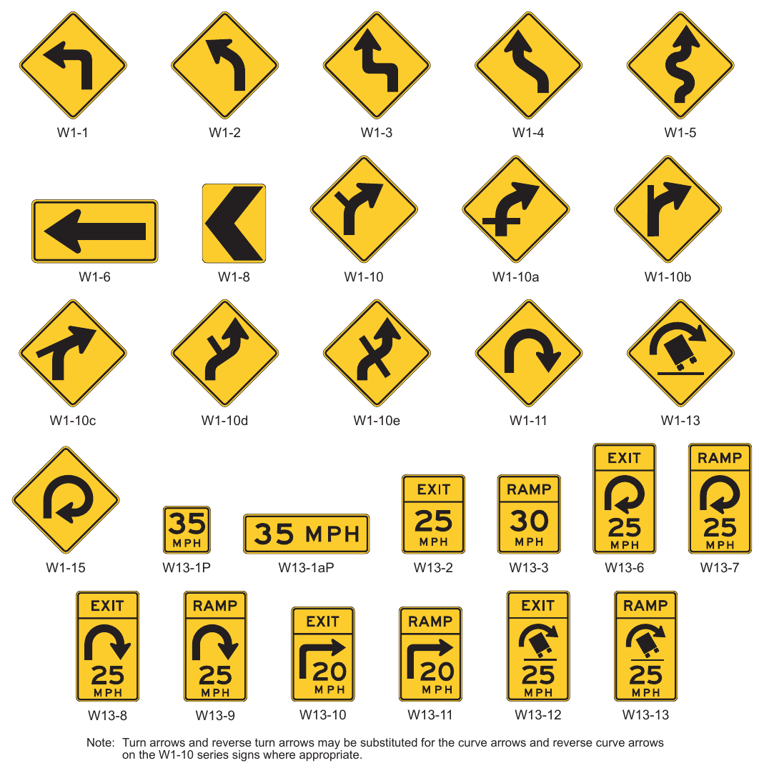
Signs shown: W1-1, W1-2, W1-3, W1-4, W1-5, W1-6, W1-8, W1-10, W1-10a, W1-10b, W1-10c, W1-10d, W1-10e, W1-11, W1-13, W1-15, W13-1P, W13-1aP, W13-2, W13-3, W13-6, W13-7, W13-8, W13-9, W13-10, W13-11, W13-12, W13-13
Note: Turn arrows and reverse turn arrows may be substituted for the curve arrows and reverse curve arrows on the W1-10 series signs where appropriate.
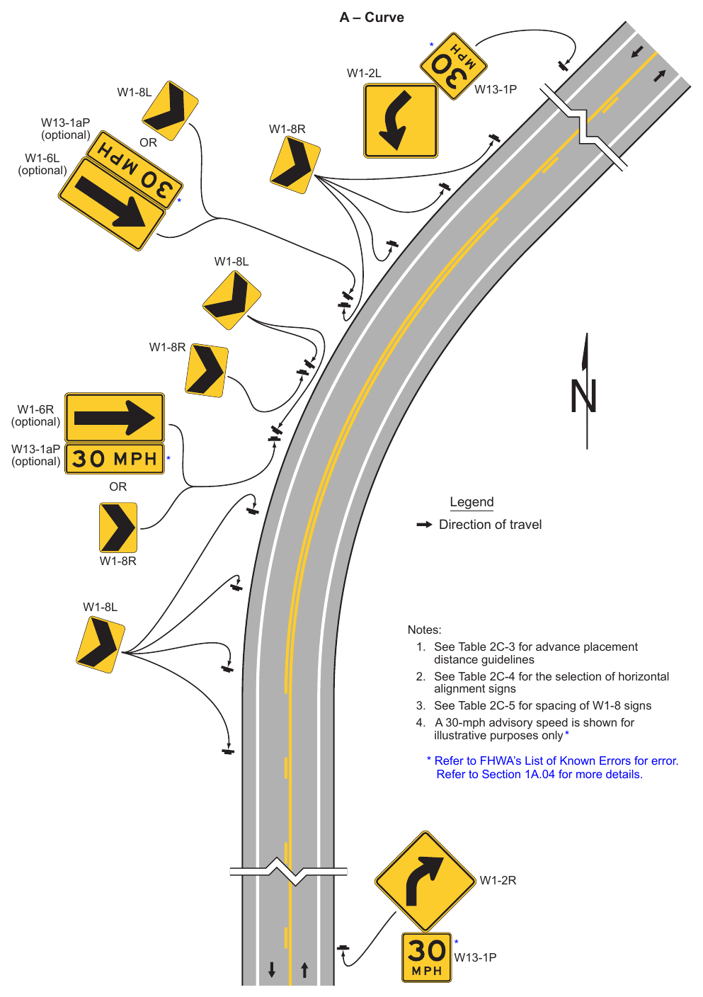
Signs shown: W1-2L, W1-8L, W13-1P, W13-1aP, W1-8R, W1-6L, W1-6R, W1-8, W1-2R
- 1. See Table 2C-3 for advance placement distance guidelines
- 2. See Table 2C-4 for the selection of horizontal alignment signs
- 3. See Table 2C-5 for spacing of W1-8 signs
- 4. A 30-mph advisory speed is shown for illustrative purposes only * Refer to Section 1A.04 for more details. W1-2R * W13-1P
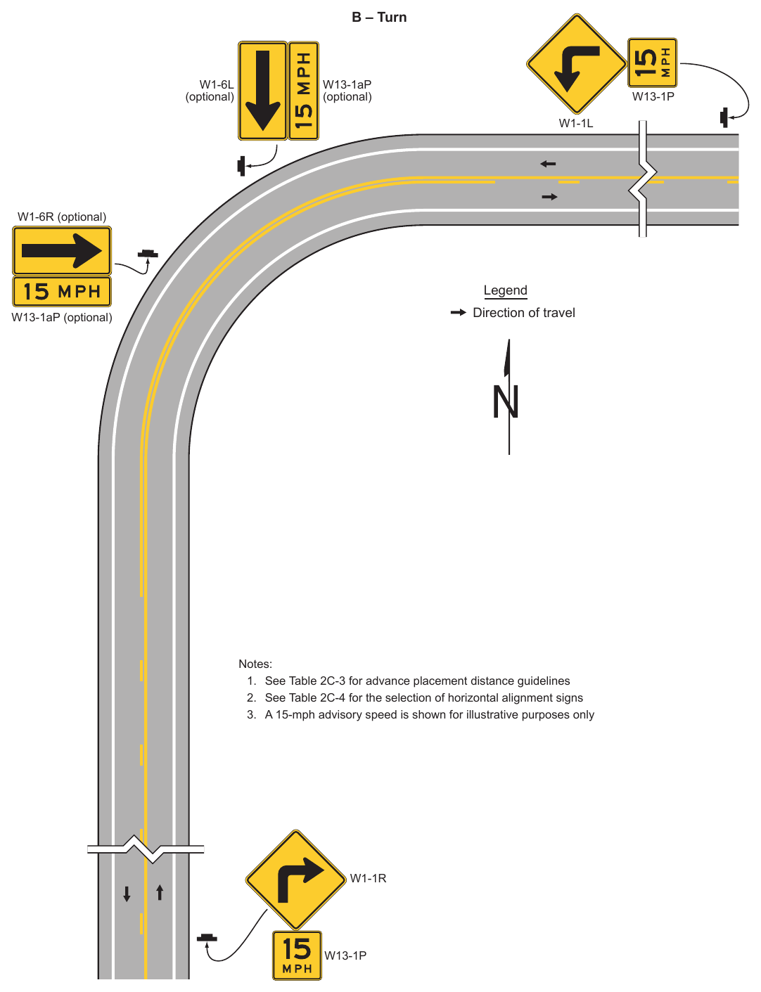
- 1. See Table 2C-3 for advance placement distance guidelines
- 2. See Table 2C-4 for the selection of horizontal alignment signs
- 3. A 15-mph advisory speed is shown for illustrative purposes only W1-1R W13-1P
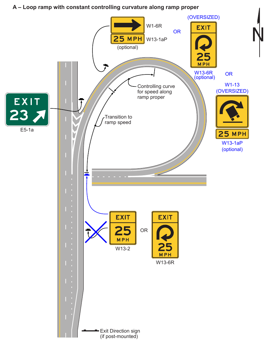
Speed and Other Warning Signs (Sheet 1 of 5) A – Loop ramp with constant controlling curvature along ramp proper W13-1aP (optional) (optional) Controlling curve for speed along ramp proper Transition to ramp speed E5-1a W13-1aP (optional) Exit Direction sign (if post-mounted)
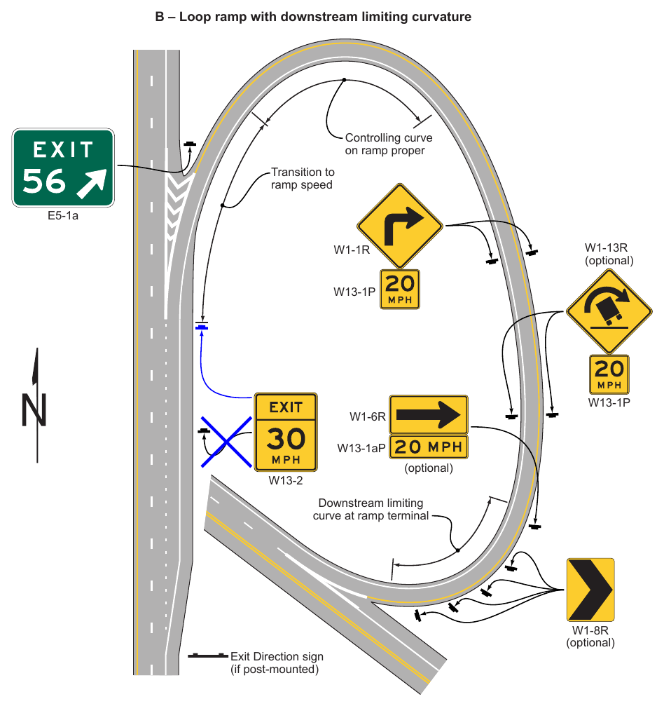
Signs shown: E5-1a, W1-1R, W1-13R, W13-1P, W1-6R, W13-1aP, W13-2, W1-8R
Speed and Other Warning Signs (Sheet 2 of 5) B – Loop ramp with downstream limiting curvature Controlling curve on ramp proper Transition to ramp speed E5-1a (optional) W13-1aP (optional) Downstream limiting curve at ramp terminal Exit Direction sign (if post-mounted) (optional)
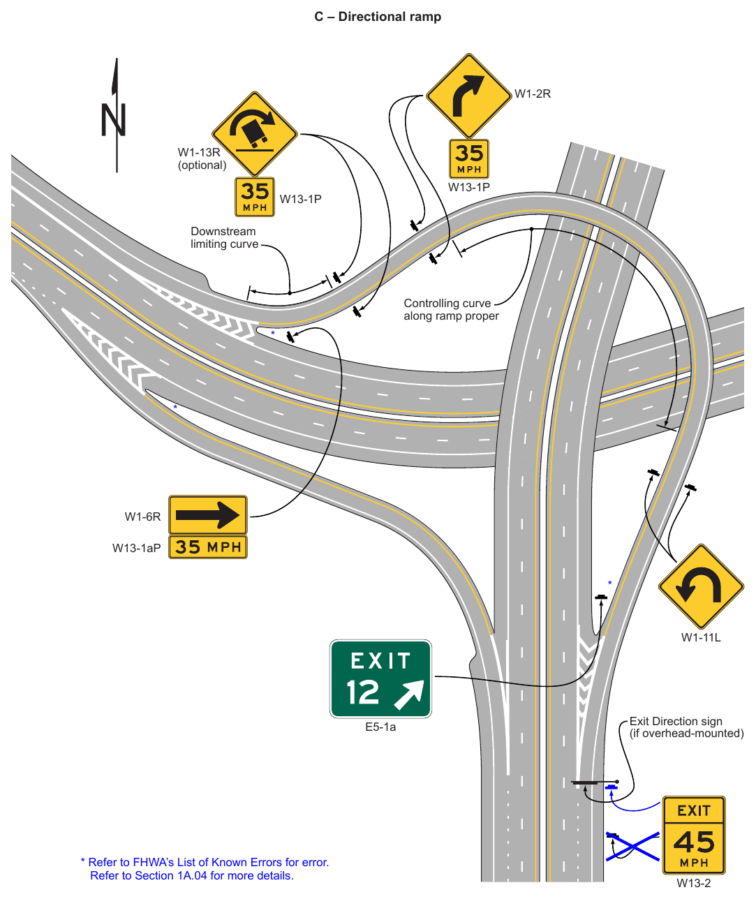
Signs shown: W1-2R, W1-13R, W13-1P, W1-6R, W13-1aP, W1-11L, E5-1a, W13-2
Speed and Other Warning Signs (Sheet 3 of 5) C – Directional ramp (optional) Downstream limiting curve Controlling curve along ramp proper W13-1aP E5-1a Refer to Section 1A.04 for more details. Exit Direction sign (if overhead-mounted)
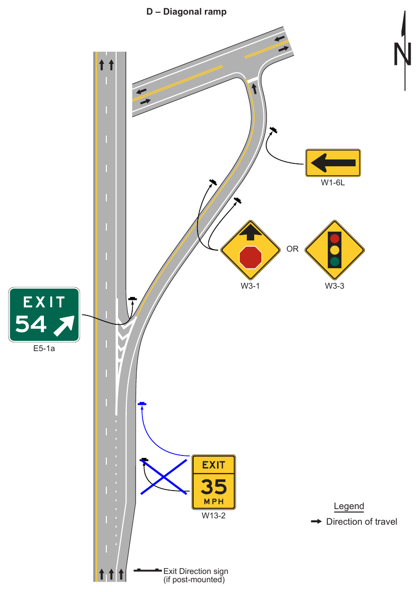
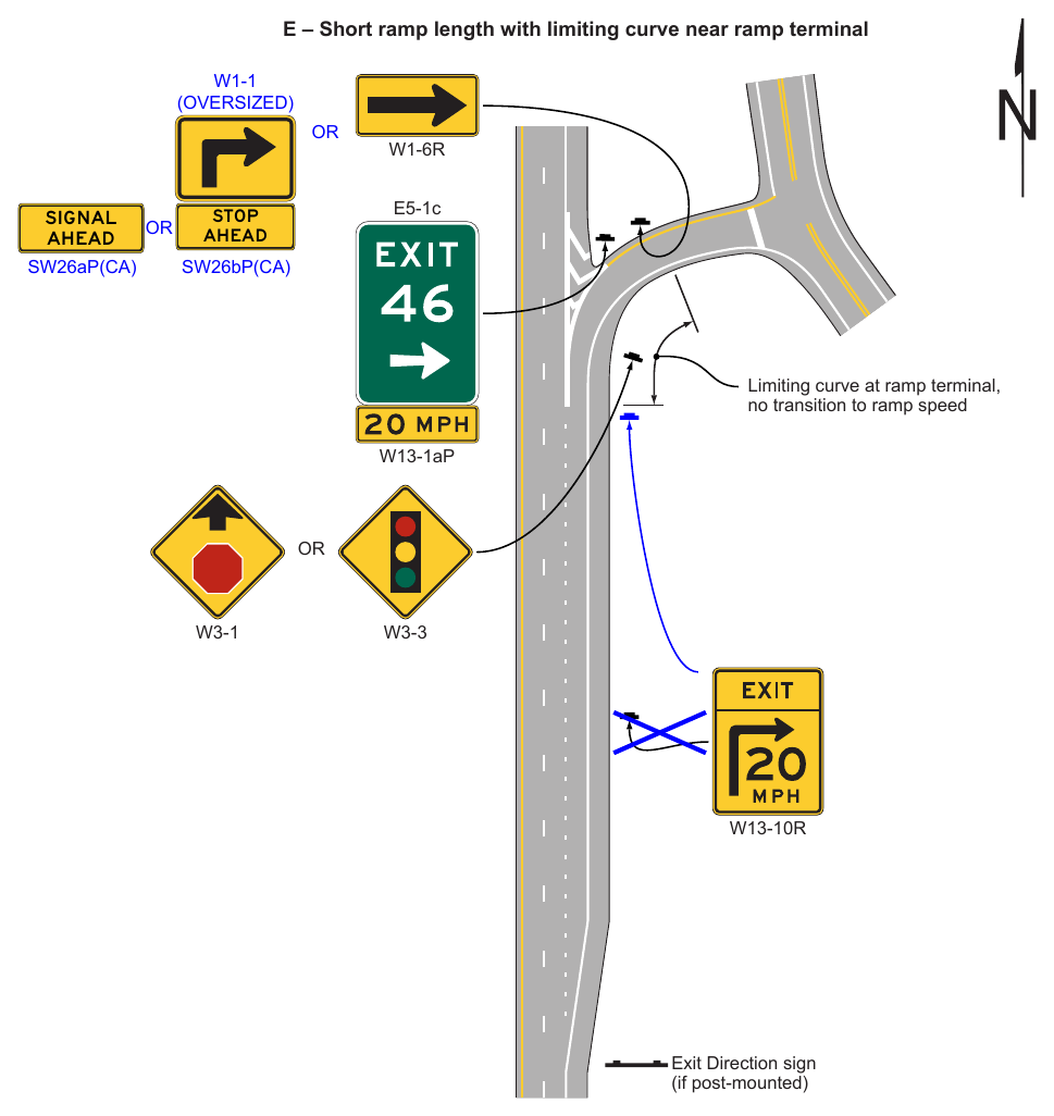
Signs shown: W1-1, W1-6R, E5-1c, W13-1aP, W3-1, W3-3, W13-10R
Speed and Other Warning Signs (Sheet 5 of 5) E – Short ramp length with limiting curve near ramp terminal SW26aP(CA) E5-1c SW26bP(CA) Limiting curve at ramp terminal, no transition to ramp speed W13-1aP Exit Direction sign (if post-mounted)
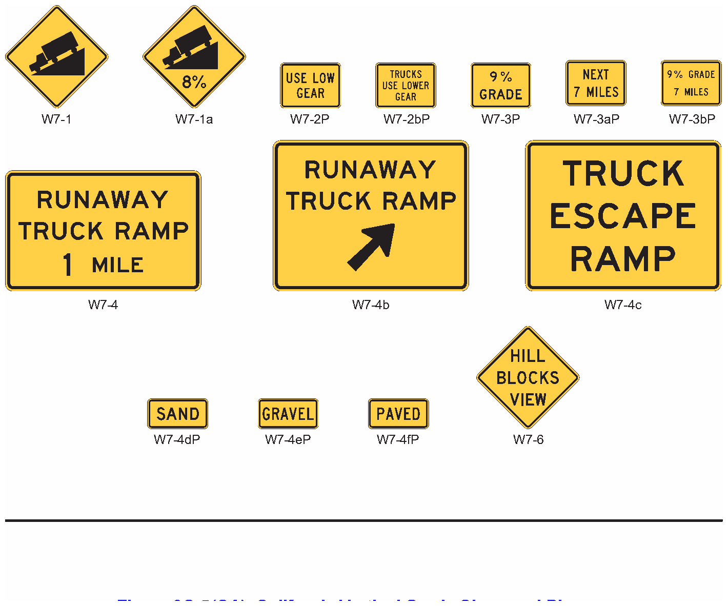
Signs shown: W7-1, W7-1a, W7-2P, W7-2bP, W7-3P, W7-3aP, W7-3bP, W7-4, W7-4b, W7-4c, W7-4dP, W7-4eP, W7-4fP, W7-6
.png)
Signs shown: SW4-1(CA)
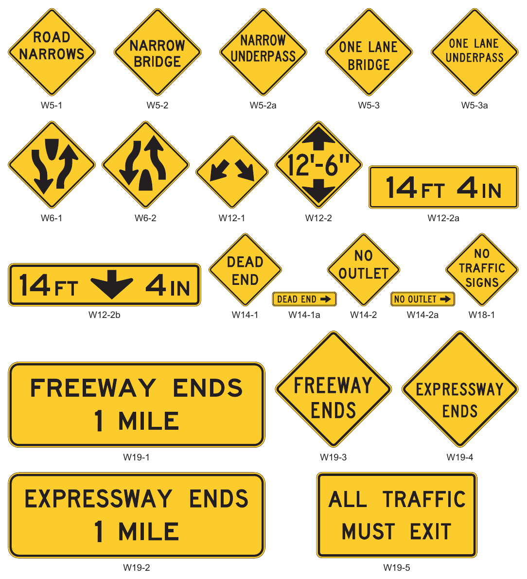
Signs shown: W5-1, W5-2, W5-2a, W5-3, W5-3a, W6-1, W6-2, W12-1, W12-2, W12-2a, W12-2b, W14-1, W14-1a, W14-2, W14-2a, W18-1, W19-1, W19-3, W19-4, W19-2, W19-5
.png)
Signs shown: SW48-1P(CA)
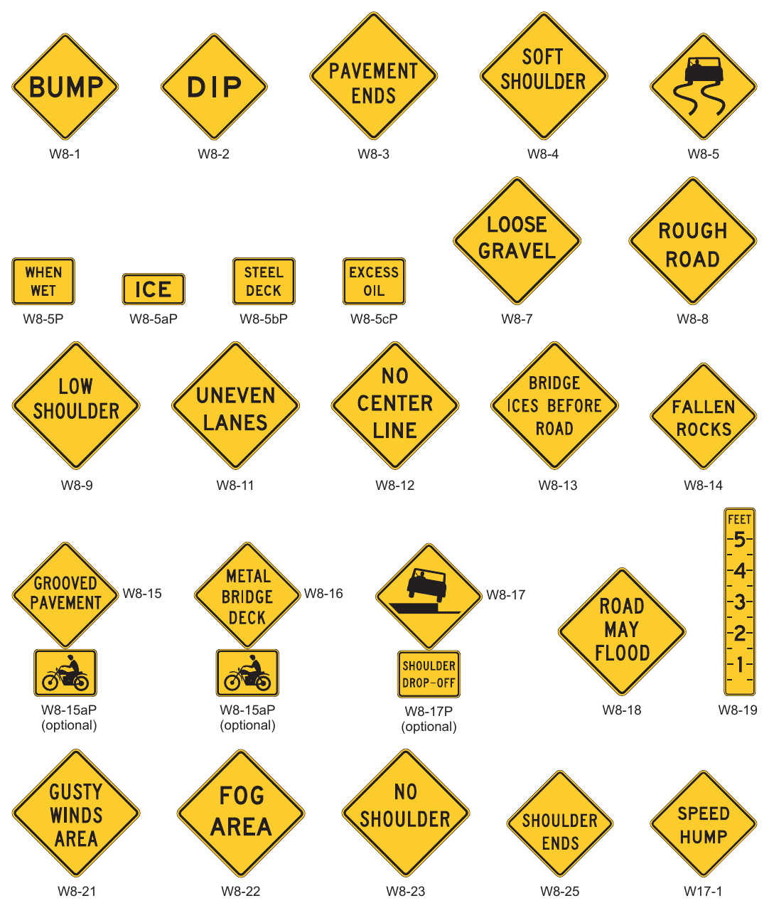
Signs shown: W8-1, W8-2, W8-3, W8-4, W8-5, W8-5P, W8-5aP, W8-5bP, W8-5cP, W8-7, W8-8, W8-9, W8-11, W8-12, W8-13, W8-14, W8-15, W8-16, W8-17, W8-15aP, W8-17P, W8-18, W8-19, W8-21, W8-22, W8-23, W8-25, W17-1
.png)
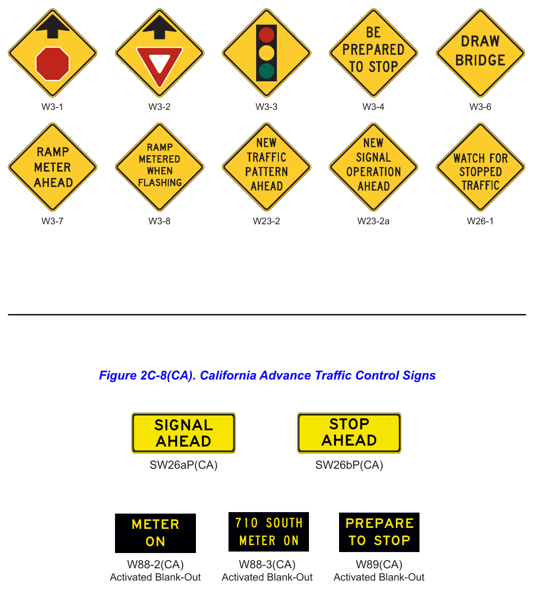
Signs shown: W3-1, W3-2, W3-3, W3-4, W3-6, W3-7, W3-8, W23-2, W23-2a, W26-1
.png)
Signs shown: W88-2(CA), W88-3(CA)
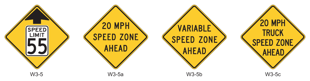
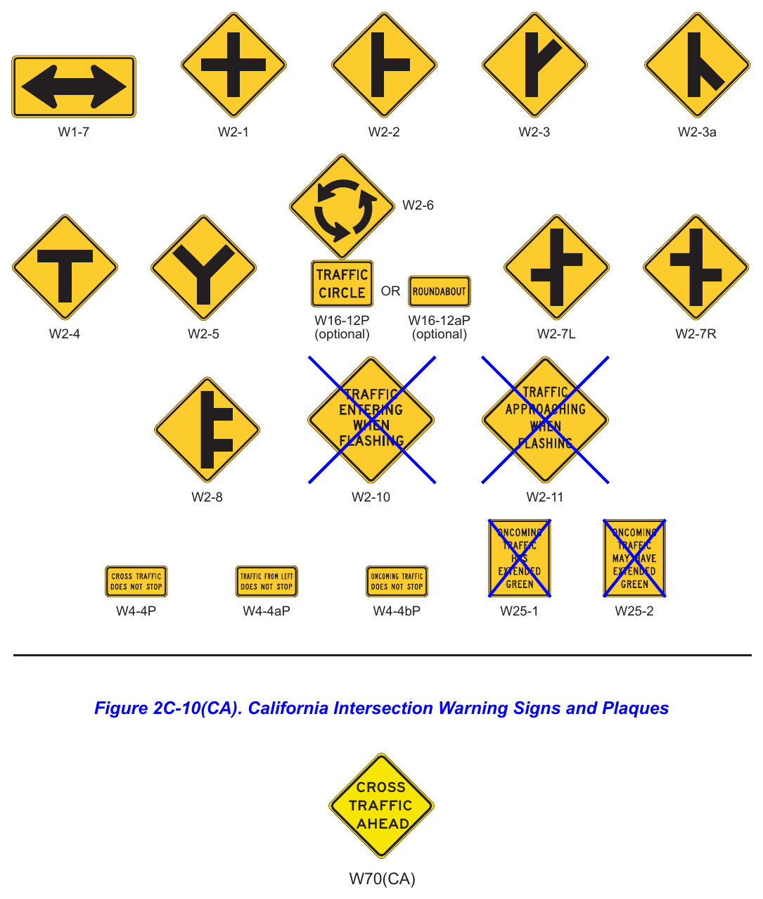
Signs shown: W1-7, W2-1, W2-2, W2-3, W2-3a, W2-6, W16-12P, W16-12aP, W2-4, W2-5, W2-7L, W2-7R, W2-8, W2-10, W2-11, W4-4P, W4-4aP, W4-4bP, W25-1, W25-2
.png)
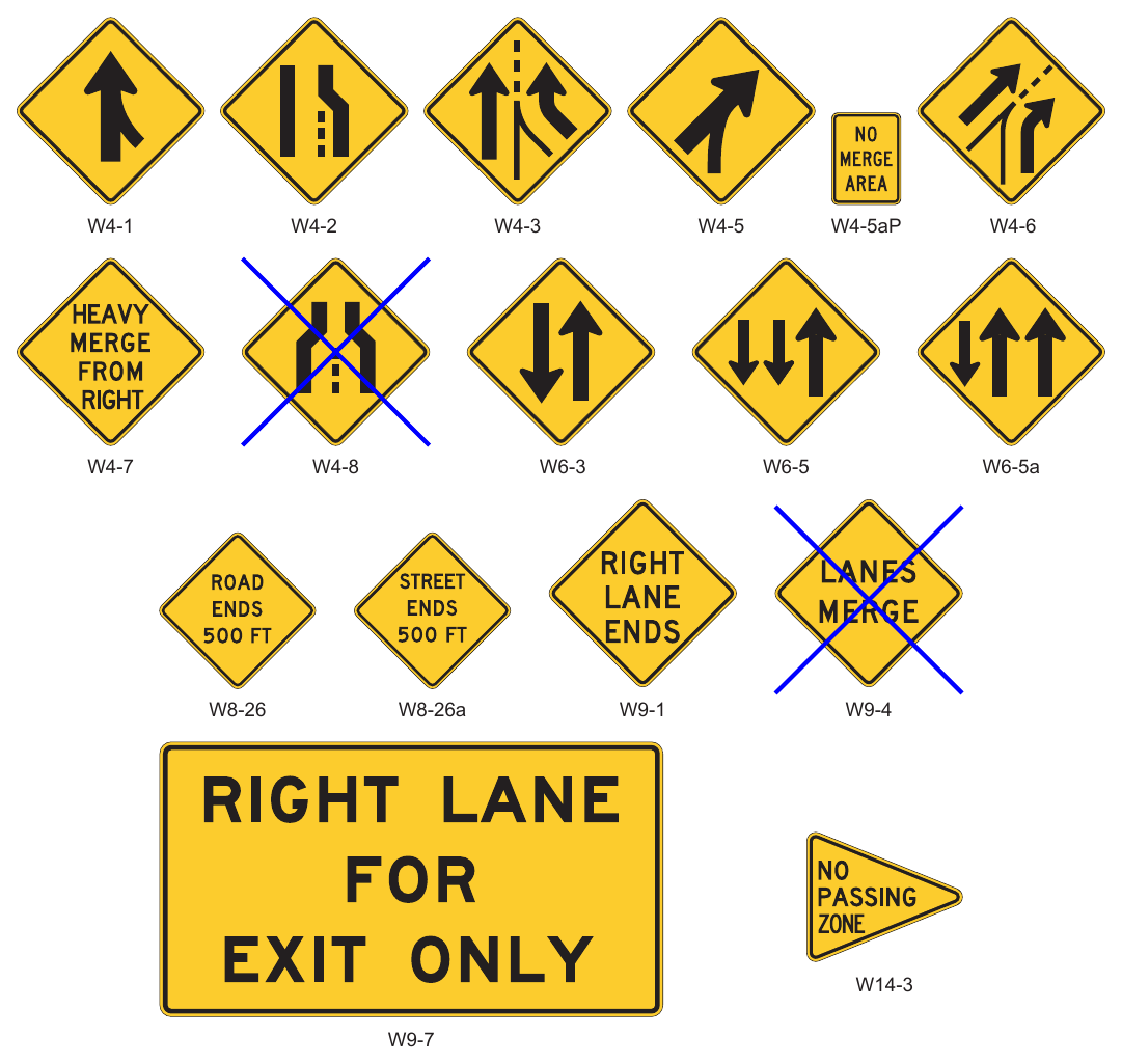
Signs shown: W4-1, W4-2, W4-3, W4-5, W4-5aP, W4-6, W4-7, W4-8, W6-3, W6-5, W6-5a, W8-26, W8-26a, W9-1, W9-4, W14-3, W9-7
.png)
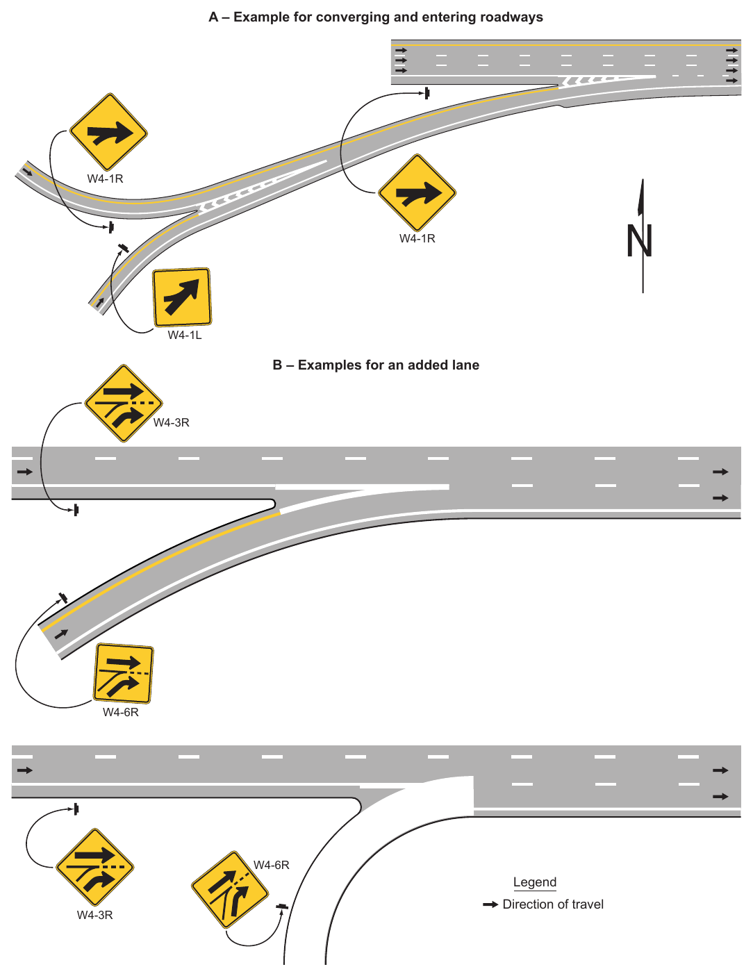
Signs shown: W4-1R, W4-1L, W4-3R, W4-6R
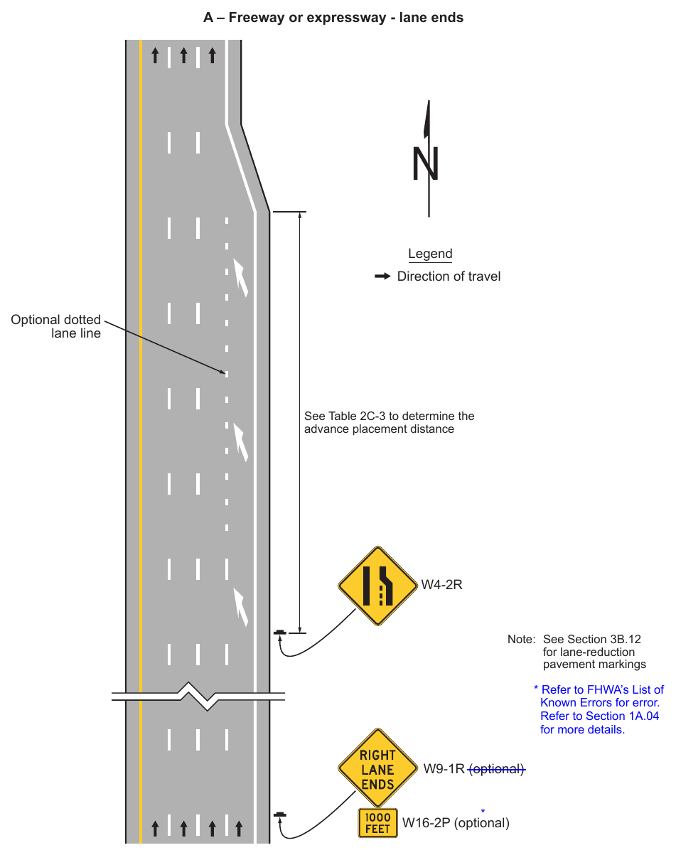
Signs shown: W4-2R, W9-1R, W16-2P
Note: See Section 3B.12 for lane-reduction pavement markings Known Errors for error. Refer to Section 1A.04 for more details. W9-1R (optional) W16-2P (optional)
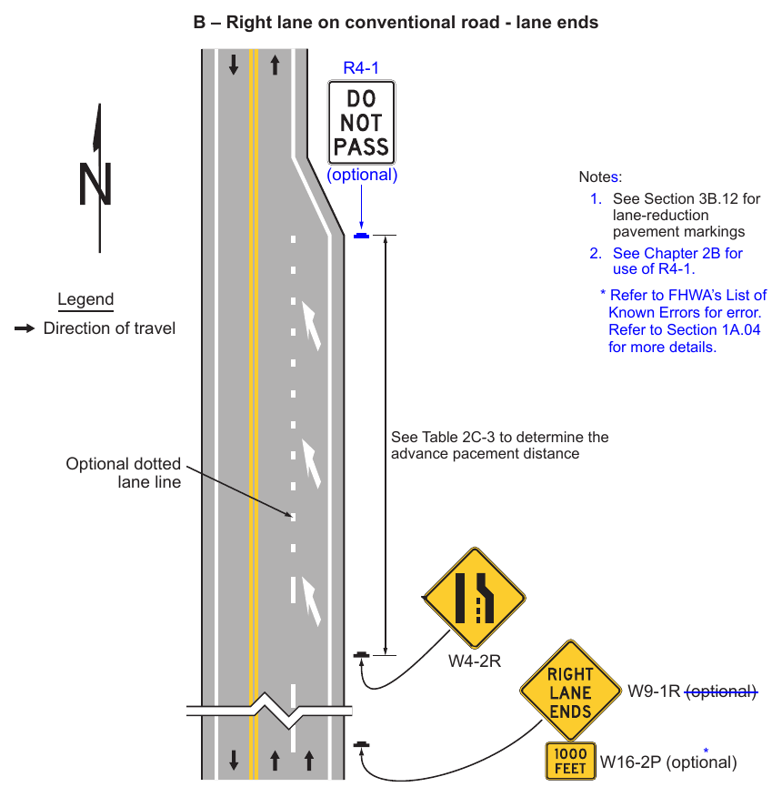
- 1. See Section 3B.12 for lane-reduction pavement markings
- 2. See Chapter 2B for use of R4-1. Known Errors for error. Refer to Section 1A.04 for more details. Legend Direction of travel Optional dotted lane line See Table 2C-3 to determine the advance pacement distance W4-2R W9-1R (optional) * W16-2P (optional)
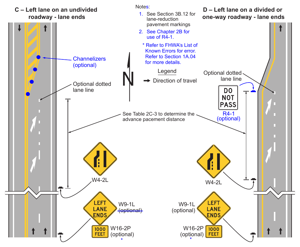
- 1. See Section 3B.12 for lane-reduction pavement markings
- 2. See Chapter 2B for use of R4-1. C – Left lane on an undivided roadway - lane ends D – Left lane on a divided or one-way roadway - lane ends Known Errors for error. Refer to Section 1A.04 for more details. Channelizers (optional) Legend Direction of travel Optional dotted lane line See Table 2C-3 to determine the advance pacement distance R4-1 (optional) Optional dotted lane line W4-2L W4-2L W9-1L (optional) W16-2P (optional) W9-1L (optional) W16-2P (optional) *
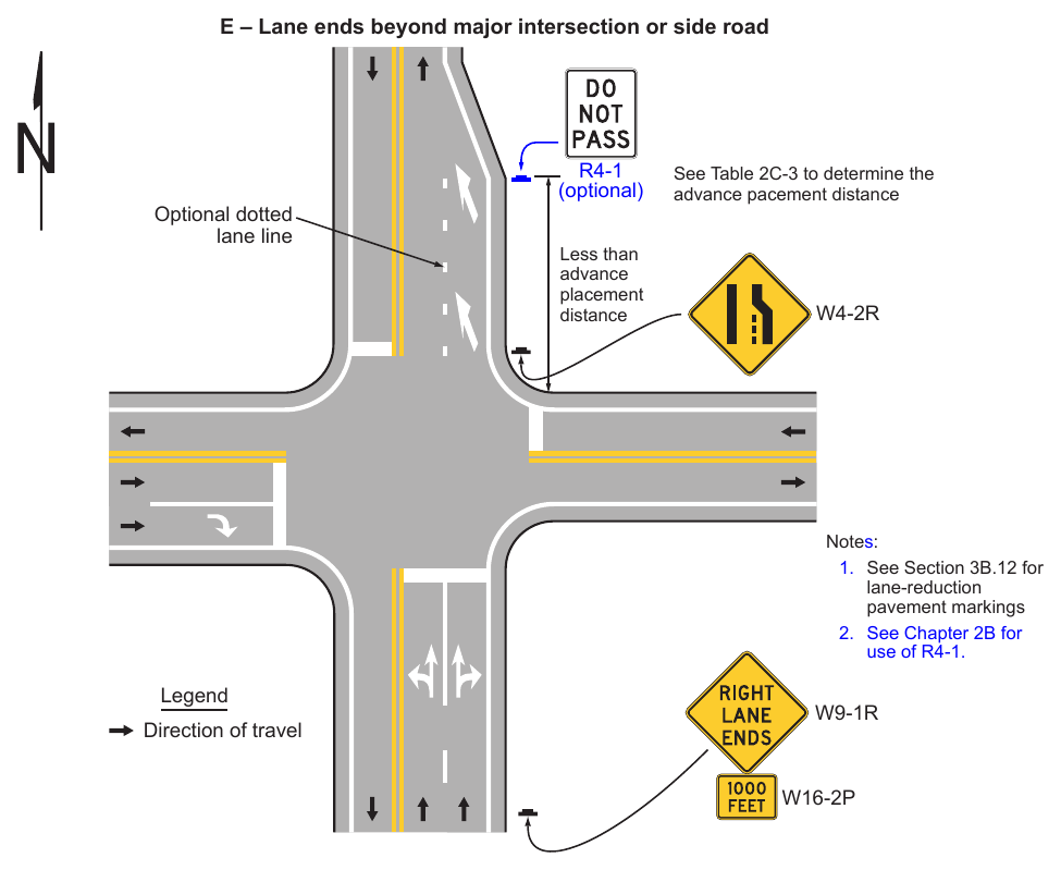
- 1. See Section 3B.12 for lane-reduction pavement markings
- 2. See Chapter 2B for use of R4-1. Legend Direction of travel W9-1R W16-2P
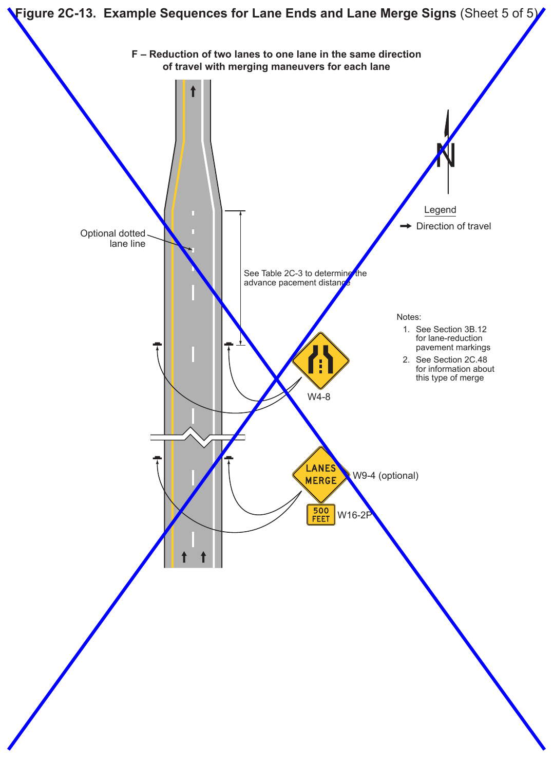
- 1. See Section 3B.12 for lane-reduction pavement markings
- 2. See Section 2C.48 for information about this type of merge W4-8 W9-4 (optional) W16-2P
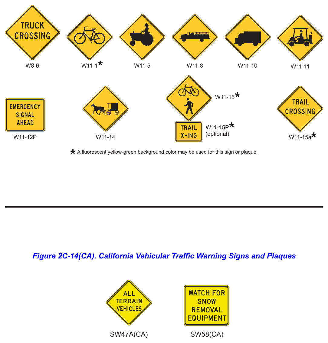
Signs shown: W8-6, W11-1, W11-5, W11-8, W11-10, W11-11, W11-15, W11-15P, W11-12P, W11-14, W11-15a
A fluorescent yellow-green background color may be used for this sign or plaque.
.png)
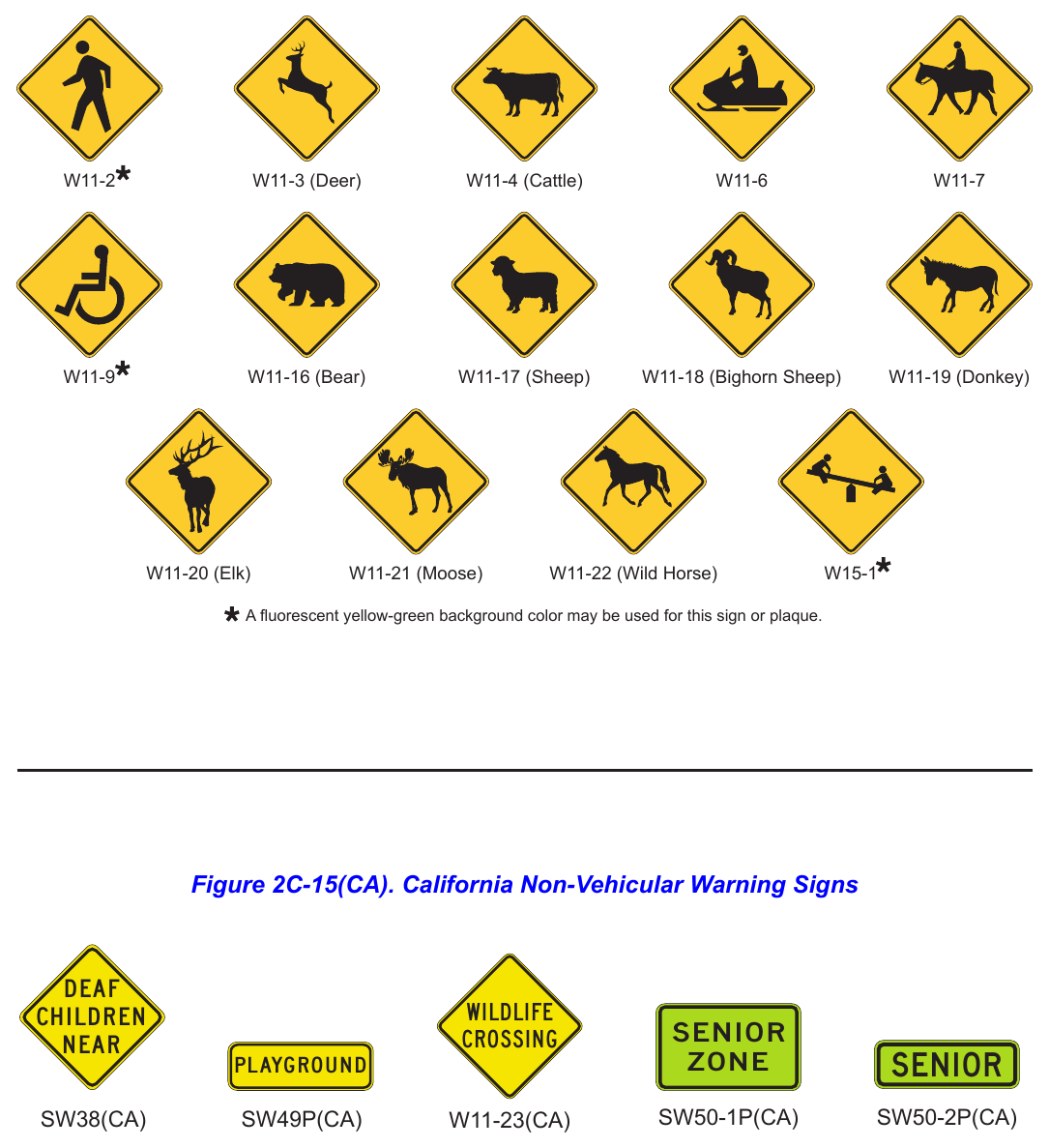
Signs shown: W11-2, W11-3, W11-4, W11-6, W11-7, W11-9, W11-16, W11-17, W11-18, W11-19, W11-20, W11-21, W11-22, W15-1
W11-3 (Deer) W11-4 (Cattle) W11-16 (Bear) W11-17 (Sheep) W11-18 (Bighorn Sheep) W11-19 (Donkey) W11-20 (Elk) W11-21 (Moose) W11-22 (Wild Horse) A fluorescent yellow-green background color may be used for this sign or plaque.
.png)
Signs shown: W11-23(CA), SW50-1P(CA), SW50-2P(CA)
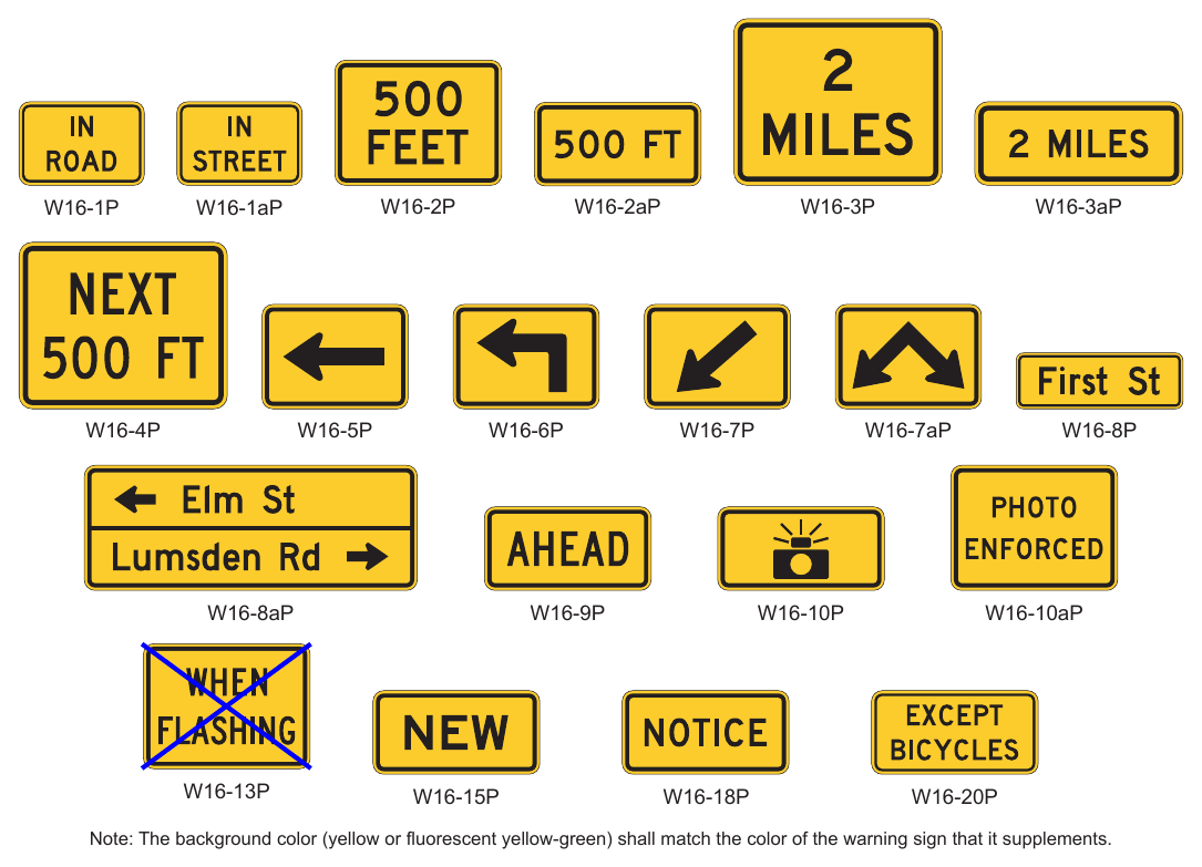
Signs shown: W16-1P, W16-1aP, W16-2P, W16-2aP, W16-3P, W16-3aP, W16-4P, W16-5P, W16-6P, W16-7P, W16-7aP, W16-8P, W16-8aP, W16-9P, W16-10P, W16-10aP, W16-13P, W16-15P, W16-18P, W16-20P
Note: The background color (yellow or fluorescent yellow-green) shall match the color of the warning sign that it supplements.
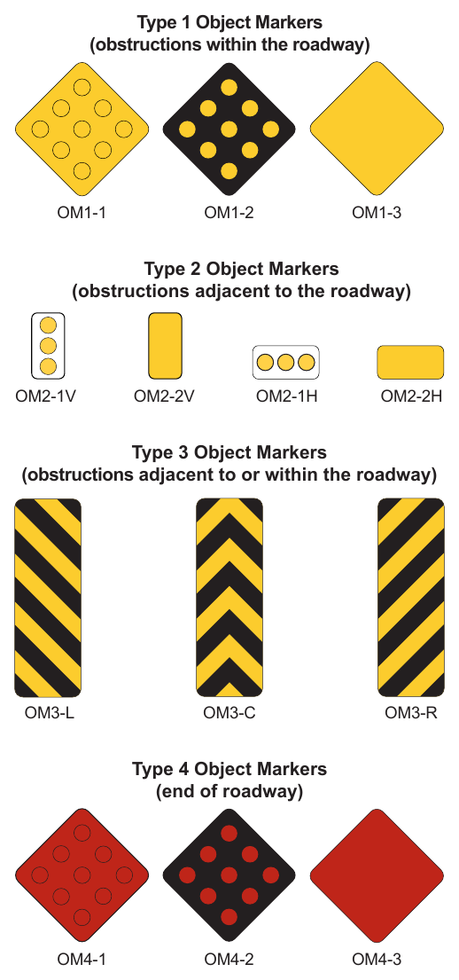
Signs shown: OM1-1, OM1-2, OM1-3, OM2-1V, OM2-2V, OM2-1H, OM2-2H, OM4-1, OM4-2, OM4-3
(obstructions within the roadway) Type 2 Object Markers (obstructions adjacent to the roadway) Type 3 Object Markers (obstructions adjacent to or within the roadway) Type 4 Object Markers (end of roadway)
.png)
Type Q(CA) Object Marker (Type 1) (obstructions within the roadway) 2.25 in. Minimum Diameter 0.75 in. spacing at the top and between bands 3 each, 3 in. bands or 1 each, 9 in. band of yellow retroreflective sheeting 18 in. - 24 in. Pavement Surface Type L(CA) Object Marker (Type 2) (obstructions adjacent to the roadway) Yellow retroreflective sheeting 12 in. (Measured along pole’s circumference) 12 in. 12 in. 2 in. Utility Pole 36 in.
20. Driver____ Observer___ Vehicle___ Date_______
35. SPEED M.P.H.
50. Type of Pavement___ Condition of Pavement___ Min. Sight Dist. Thru Curve_ Approach Speed (Estimated or Observed)_____
65. Limit Line For Trucks (see Section 2C.11)
70. Limit Line (see Section 2C.59) Co._Rte.PM Sta.___To_ Direction__ Weather___
.png)
Table 2C-1. Warning Sign and Plaque Sizes (Sheet 1 of 4)
| Sign or Plaque | Sign Designation | Section | Conventional Road | Expressway | Freeway | Minimum | Oversized | |
|---|---|---|---|---|---|---|---|---|
| Single Lane | Multi-Lane | |||||||
| Horizontal Alignment | W1-1,2,3,4,5 | 2C.07 | 30 x 30* | 36 x 36 | 36 x 36 | 36 x 36 | — | 48 x 48** |
| One-Direction Large Arrow | W1-6 | 2C.10 | 48 x 24 | 48 x 24 | 60 x 30 | 60 x 30 | — | 60 x 30 |
| Two-Direction Large Arrow | W1-7 | 2C.43 | 48 x 24 | 48 x 24 | — | — | — | 60 x 30 |
| Chevron Alignment | W1-8 | 2C.08 | 18 x 24 | 18 x 24 | 30 x 36 | 36 x 48 | — | 24 x 30 |
| Combination Horizontal | W1-10,10a,10b, | |||||||
| 2C.09 | 36 x 36 | 36 x 36 | 36 x 36 | 48 x 48 | — | — | ||
| Alignment/Intersection | 10c,10d,10e | |||||||
| Hairpin Curve | W1-11 | 2C.07 | 30 x 30 | 30 x 30 | 36 x 36 | 48 x 48 | — | 48 x 48 |
| Truck Rollover | W1-13 | 2C.11 | 36 x 36 | 36 x 36 | 36 x 36 | 48 x 48 | — | 48 x 48 |
| 270-degree Curve | W1-15 | 2C.07 | 30 x 30 | 30 x 30 | 36 x 36 | 48 x 48 | — | 48 x 48 |
| W2-1,2,3,3a, | ||||||||
| Intersection Warning | 2C.41 | 30 x 30 | 30 x 30 | 36 x 36 | — | 24 x 24 | 48 x 48 | |
| 4,5,6,7,8 | ||||||||
| Traffic Entering When Flashing | W2-10 | 2C.42 | 36 x 36 | 36 x 36 | 48 x 48 | — | — | — |
| Traffic Approaching When | ||||||||
| Flashing | W2-11 | 2C.42 | 36 x 36 | 36 x 36 | 48 x 48 | — | — | — |
| Stop, Yield, Signal Ahead | W3-1,2,3 | 2C.35 | 30 x 30 | 30 x 30 | 48 x 48 | 48 x 48 | 30 x 30 | — |
| Be Prepared to Stop | W3-4 | 2C.35 | 36 x 36 | 36 x 36 | 48 x 48 | 48 x 48 | 30 x 30 | — |
| Reduced Speed Limit Ahead | W3-5 | 2C.40 | 36 x 36 | 36 x 36 | 48 x 48 | 48 x 48 | — | — |
| XX MPH Speed Zone Ahead | W3-5a | 2C.40 | 36 x 36 | 36 x 36 | 48 x 48 | 48 x 48 | — | — |
| Variable Speed Zone Ahead | W3-5b | 2C.40 | 36 x 36 | 36 x 36 | 48 x 48 | 48 x 48 | — | — |
| XX MPH Truck Speed Zone Ahead | W3-5c | 2C.40 | 36 x 36 | 36 x 36 | 48 x 48 | 48 x 48 | — | — |
| Draw Bridge | W3-6 | 2C.36 | 36 x 36 | 36 x 36 | 48 x 48 | — | — | 60 x 60 |
| Ramp Meter Ahead | W3-7 | 2C.37 | 36 x 36 | 36 x 36 | — | — | — | — |
| Ramp Metered When Flashing | W3-8 | 2C.37 | 36 x 36 | 36 x 36 | — | — | — | — |
| Merge | W4-1 | 2C.45 | 36 x 36 | 36 x 36 | 48 x 48 | 48 x 48 | 30 x 30* | — |
| Lane Ends | W4-2 | 2C.47 | 36 x 36 | 36 x 36 | 48 x 48 | 48 x 48 | 30 x 30* | — |
| Added Lane | W4-3 | 2C.46 | 36 x 36 | 36 x 36 | 48 x 48 | 48 x 48 | 30 x 30* | — |
| Cross Traffic Does Not Stop (plaque) | W4-4P | 2C.66 | 24 x 12 | 24 x 12 | 36 x 18 | — | — | 48 x 24 |
| Traffic From Left (Right) Does Not | ||||||||
| W4-4aP | 2C.66 | 24 x 12 | 24 x 12 | 36 x 18 | — | — | 48 x 24 | |
| Stop (plaque) | ||||||||
| Oncoming Traffic Does Not Stop (plaque) | W4-4bP | 2C.66 | 24 x 12 | 24 x 12 | 36 x 18 | — | — | 48 x 24 |
| Entering Roadway Merge | W4-5 | 2C.45 | 36 x 36 | 36 x 36 | 48 x 48 | 48 x 48 | — | — |
| No Merge Area (plaque) | W4-5aP | 2C.45 | 18 x 24 | 18 x 24 | 24 x 30 | 24 x 30 | — | — |
| Entering Roadway Added Lane | W4-6 | 2C.46 | 36 x 36 | 36 x 36 | 48 x 48 | 48 x 48 | — | — |
| Heavy Merge from Right (Left) | W4-7 | 2C.49 | 36 x 36 | 36 x 36 | 48 x 48 | 48 x 48 | — | |
| 48 x 48 | ||||||||
| Single Lane Transition | W4-8 | 2C.48 | 36 x 36 | 36 x 36 | 36 x 36 | 48 x 48 | — | |
| Road Narrows | W5-1 | 2C.17 | 36 x 36 | 36 x 36 | 48 x 48 | 48 x 48 | 30 x 30* | — |
| Narrow Bridge | W5-2 | 2C.18 | 36 x 36 | 36 x 36 | 48 x 48 | 48 x 48 | 30 x 30* | — |
| Narrow Underpass | W5-2a | 2C.18 | 36 x 36 | 36 x 36 | 48 x 48 | 48 x 48 | 30 x 30* | |
| One Lane Bridge | W5-3 | 2C.19 | 36 x 36 | 36 x 36 | 48 x 48 | 48 x 48 | 30 x 30* | — |
| One Lane Underpass | W5-3a | 2C.19 | 36 x 36 | 36 x 36 | 48 x 48 | 48 x 48 | 30 x 30* | |
| Divided Highway | W6-1 | 2C.20 | 36 x 36 | 36 x 36 | 48 x 48 | 48 x 48 | — | — |
| Divided Highway Ends | W6-2 | 2C.21 | 36 x 36 | 36 x 36 | 48 x 48 | 48 x 48 | — | — |
| Two-Way Traffic | W6-3 | 2C.51 | 36 x 36 | 36 x 36 | 48 x 48 | 48 x 48 | — | — |
| Two-Way Traffic (3-Lane) | W6-5 | 2C.52 | 36 x 36 | 36 x 36 | 48 x 48 | — | — | — |
| Two-Way Traffic (3-Lane) | W6-5a | 2C.52 | 36 x 36 | 36 x 36 | 48 x 48 | — | — | — |
| Hill | W7-1 | 2C.14 | 30 x 30* | 36 x 36 | 36 x 36 | 36 x 36 | 24 x 24* | 48 x 48 |
| Hill with Grade | W7-1a | 2C.14 | 30 x 30* | 36 x 36 | 36 x 36 | 36 x 36 | 24 x 24* | 48 x 48 |
Table 2C-1. Warning Sign and Plaque Sizes (Sheet 2 of 4)
| Sign or Plaque | Sign Designation | Section | Conventional Road | Expressway | Freeway | Minimum | Oversized | |
|---|---|---|---|---|---|---|---|---|
| Single Lane | Multi-Lane | |||||||
| Use Low Gear (plaque) | W7-2P | 2C.64 | 24 x 18 | 24 x 18 | — | — | — | — |
| Trucks Use Lower Gear (plaque) | W7-2bP | 2C.64 | 24 x 18 | 24 x 18 | — | — | — | — |
| XX% Grade (plaque) | W7-3P | 2C.64 | 24 x 18 | 24 x 18 | — | — | — | — |
| Next XX Miles (plaque) | W7-3aP | 2C.61 | 24 x 18 | 24 x 18 | — | — | — | — |
| XX% Grade, XX Miles (plaque) | W7-3bP | 2C.64 | 24 x 18 | 24 x 18 | — | — | — | — |
| Runaway Truck Ramp XX Miles | W7-4 | 2C.15 | 84 x 48 | 84 x 48 | 120 x 72 | 120 x 72 | — | — |
| Runaway Truck Ramp Entrance | ||||||||
| W7-4b | 2C.15 | 84 x 54 | 84 x 54 | 120 x 78 | 120 x 78 | — | — | |
| Direction | ||||||||
| Truck Escape Ramp | W7-4c | 2C.15 | 78 x 60 | 78 x 60 | 78 x 60 | 78 x 60 | — | — |
| W7-4dP, | ||||||||
| Sand, Gravel, Paved (plaques) | 2C.15 | 24 x 12 | 24 x 12 | 24 x 12 | 24 x 12 | — | — | |
| 4eP,4fP | ||||||||
| Hill Blocks View | W7-6 | 2C.16 | 30 x 30* | 36 x 36 | 36 x 36 | — | — | 48 x 48 |
| Bump or Dip | W8-1,2 | 2C.26 | 30 x 30* | 36 x 36 | 36 x 36 | 48 x 48 | 24 x 24* | 48 x 48 |
| Pavement Ends | W8-3 | 2C.28 | 36 x 36 | 36 x 36 | 48 x 48 | — | 30 x 30* | — |
| Soft Shoulder | W8-4 | 2C.29 | 36 x 36 | 36 x 36 | 48 x 48 | 48 x 48 | 24 x 24* | 48 x 48 |
| Slippery When Wet | W8-5 | 2C.30 | 30 x 30* | 36 x 36 | 36 x 36 | 48 x 48 | 24 x 24* | 48 x 48 |
| Road Condition (plaques) | W8-5P,5bP,5cP | 2C.30 | 24 x 18 | 24 x 18 | 30 x 24 | 36 x 30 | — | 36 x 30 |
| Ice (plaque) | W8-5aP | 2C.30 | 24 x 12 | 24 x 12 | 30 x 18 | 30 x 18 | — | — |
| Truck Crossing | W8-6 | 2C.54 | 36 x 36 | 36 x 36 | 36 x 36 | 48 x 48 | 24 x 24* | 48 x 48 |
| Loose Gravel | W8-7 | 2C.30 | 36 x 36 | 36 x 36 | 36 x 36 | — | 24 x 24* | 48 x 48 |
| Rough Road | W8-8 | 2C.30 | 36 x 36 | 36 x 36 | 36 x 36 | 48 x 48 | 24 x 24* | 48 x 48 |
| Low Shoulder | W8-9 | 2C.29 | 36 x 36 | 36 x 36 | 36 x 36 | 48 x 48 | 24 x 24* | 48 x 48 |
| Uneven Lanes | W8-11 | 2C.30 | 36 x 36 | 36 x 36 | 36 x 36 | 48 x 48 | — | 48 x 48 |
| No Center Line | W8-12 | 2C.32 | 36 x 36 | 36 x 36 | 36 x 36 | 48 x 48 | — | — |
| Bridge Ices Before Road | W8-13 | 2C.30 | 36 x 36 | 36 x 36 | 36 x 36 | 48 x 48 | 24 x 24* | 48 x 48 |
| Fallen Rocks | W8-14 | 2C.30 | 30 x 30* | 36 x 36 | 36 x 36 | 48 x 48 | 24 x 24* | 48 x 48 |
| Grooved Pavement | W8-15 | 2C.31 | 30 x 30* | 36 x 36 | 36 x 36 | 48 x 48 | 24 x 24* | 48 x 48 |
| Motorcycle (plaque) | W8-15aP | 2C.31 | 24 x 18 | 24 x 18 | 30 x 24 | 36 x 30 | — | 36 x 30 |
| Metal Bridge Deck | W8-16 | 2C.31 | 30 x 30* | 36 x 36 | 36 x 36 | 48 x 48 | 24 x 24* | 48 x 48 |
| Shoulder Drop-Off | W8-17 | 2C.29 | 30 x 30* | 36 x 36 | 36 x 36 | 48 x 48 | 24 x 24* | 48 x 48 |
| Shoulder Drop-Off (plaque) | W8-17P | 2C.29 | 24 x 18 | 24 x 18 | 30 x 24 | 36 x 30 | — | 36 x 30 |
| Road May Flood | W8-18 | 2C.34 | 36 x 36 | 36 x 36 | 36 x 36 | 48 x 48 | 24 x 24* | 48 x 48 |
| Depth Gauge | W8-19 | 2C.34 | 12 x 72 | 12 x 72 | — | — | — | — |
| Gusty Winds Area | W8-21 | 2C.34 | 36 x 36 | 36 x 36 | 36 x 36 | 48 x 48 | 24 x 24* | 48 x 48 |
| Fog Area | W8-22 | 2C.34 | 36 x 36 | 36 x 36 | 36 x 36 | 48 x 48 | 24 x 24* | 48 x 48 |
| No Shoulder | W8-23 | 2C.29 | 36 x 36 | 36 x 36 | 36 x 36 | 48 x 48 | 24 x 24* | 48 x 48 |
| Shoulder Ends | W8-25 | 2C.29 | 30 x 30* | 36 x 36 | 36 x 36 | 48 x 48 | 24 x 24* | 48 x 48 |
| Road Ends | W8-26 | 2C.24 | 30 x 30 | 36 x 36 | — | — | — | — |
| Street Ends | W8-26a | 2C.24 | 30 x 30 | 36 x 36 | — | — | — | — |
| Right (Left) Lane Ends | W9-1 | 2C.47 | 36 x 36 | 36 x 36 | 36 x 36 | 48 x 48 | 30 x 30* | 48 x 48 |
| Lanes Merge | ||||||||
| W9-4 | 2C.48 | 36 x 36 | 36 x 36 | 36 x 36 | 48 x 48 | 30 x 30* | 48 x 48 | |
| Right (Left) Lane for Exit Only | W9-7 | 2C.50 | 132 x 72 | 132 x 72 | 132 x 72 | 132 x 72 | — | — |
| Bicycle | W11-1 | 2C.54 | 30 x 30 | 30 x 30 | 36 x 36 | — | — | 48 x 48 |
| Pedestrian | W11-2 | 2C.55 | 30 x 30* | 36 x 36 | 36 x 36 | — | — | 48 x 48 |
| W11-3,4,16,17, | ||||||||
| Large Animals | 2C.55 | 30 x 30* | 36 x 36 | 36 x 36 | — | 24 x 24* | 48 x 48 | |
| 18,19,20,21,22 | ||||||||
| Farm Vehicle | W11-5 | 2C.54 | 30 x 30* | 36 x 36 | 36 x 36 | — | 24 x 24* | 48 x 48 |
| Snowmobile | W11-6 | 2C.55 | 30 x 30* | 36 x 36 | 36 x 36 | — | 24 x 24* | 48 x 48 |
| Equestrian | W11-7 | 2C.55 | 30 x 30* | 36 x 36 | 36 x 36 | — | 24 x 24* | 48 x 48 |
Table 2C-1. Warning Sign and Plaque Sizes (Sheet 3 of 4)
| Sign or Plaque | Sign Designation | Section | Conventional Road | Expressway | Freeway | Minimum | Oversized | |
|---|---|---|---|---|---|---|---|---|
| Single Lane | Multi-Lane | |||||||
| Emergency Vehicle | W11-8 | 2C.54 | 30 x 30* | 36 x 36 | 36 x 36 | — | 24 x 24* | 48 x 48 |
| Handicapped | W11-9 | 2C.55 | 30 x 30* | 36 x 36 | 36 x 36 | — | — | 48 x 48 |
| Truck | W11-10 | 2C.54 | 30 x 30* | 36 x 36 | 36 x 36 | — | 24 x 24* | 48 x 48 |
| Golf Cart | W11-11 | 2C.54 | 30 x 30* | 36 x 36 | 36 x 36 | — | 24 x 24* | 48 x 48 |
| Emergency Signal Ahead (plaque) | W11-12P | 2C.54 | 36 x 30 | 36 x 30 | 36 x 30 | — | — | — |
| Horse-Drawn Vehicle | W11-14 | 2C.54 | 30 x 30* | 36 x 36 | 36 x 36 | — | 24 x 24* | 48 x 48 |
| Trail Crossing | W11-15 | 2C.54 | 30 x 30* | 36 x 36 | 36 x 36 | — | 24 x 24* | 48 x 48 |
| Trail Crossing | W11-15a | 2C.54 | 30 x 30* | 36 x 36 | 36 x 36 | — | 24 x 24* | 48 x 48 |
| Trail Crossing (plaque) | W11-15P | 2C.54 | 24 x 18 | 24 x 18 | 30 x 24 | — | — | 36 x 30 |
| Double Arrow | W12-1 | 2C.23 | 30 x 30* | 36 x 36 | 36 x 36 | — | — | — |
| Low Clearance Advance | W12-2 | 2C.25 | 36 x 36 | 36 x 36 | 48 x 48 | 48 x 48 | 30 x 30* | — |
| Low Clearance Overhead | W12-2a | 2C.25 | 84 x 24 | 84 x 24 | 84 x 24 | 84 x 24 | — | — |
| Low Clearance - Lane Overhead | W12-2b | 2C.25 | 102 x 24 | 102 x 24 | 102 x 24 | 102 x 24 | — | — |
| Advisory Speed (plaque) | W13-1P | 2C.59 | 18 x 18 | 18 x 18 | 24 x 24 | 30 x 30 | — | 30 x 30 |
| Advisory Speed Confirmation | ||||||||
| W13-1aP | 2C.59 | 48 x 15 | 48 x 15 | 60 x 18 | 60 x 18 | 48 x 15 | 72 x 24 | |
| (plaque) | ||||||||
| Advisory Exit or Ramp Speed | W13-2,3 | 2C.12 | 24 x 30 | 24 x 30 | 36 x 48 | 36 x 48 | — | 48 x 60 |
| Combination Horizontal | ||||||||
| Alignment/Advisory Exit or Ramp | W13-6,7,8,9 | 2C.12 | 24 x 42 | 24 x 42 | 36 x 66 | 36 x 66 | — | 48 x 84 |
| Speed Loop | 72 x 126 | |||||||
| Combination Horizontal Alignment/Advisory Exit or Ramp Speed Turn | W13-10,11 | 2C.12 | 24 x 36 | 24 x 36 | 36 x 54 | 36 x 54 | — | 48 x 72 |
| Combination Horizontal | ||||||||
| Alignment/Advisory Exit or Ramp | W13-12,13 | 2C.12 | 24 x 42 | 24 x 42 | 36 x 66 | 36 x 66 | — | 48 x 84 |
| Speed - Truck Rollover | 72 x 126 | |||||||
| Vehicle Speed Feedback Sign | W13-20 | 2C.13 | 24 x 30 | 30 x 36 | 36 x 48 | 48 x 60 | — | — |
| Vehicle Speed Feedback (plaque) | W13-20aP | 2C.13 | 24 x 18 | 30 x 24 | 36 x 30 | 48 x 36 | — | — |
| Dead End, No Outlet | W14-1,2 | 2C.24 | 30 x 30* | 36 x 36 | 36 x 36 | — | 24 x 24* | 48 x 48 |
| Dead End, No Outlet (with arrow) | W14-1a,2a | 2C.24 | 36 x 9 | 36 x 9 | — | — | — | — |
| No Passing Zone | W14-3 | 2C.53 | 48 x 48 x 36 | 48 x 48 x 36 | 64 x 64 x 48 | 64x64x48 | 40 x 40 x 30 | 64 x 64 x 48 |
| Playground | W15-1 | 2C.56 | 30 x 30* | 36 x 36 | 36 x 36 | — | 24 x 24* | 48 x 48 |
| In Road (plaque) | W16-1P | 2C.67 | 18 x 12 | 18 x 12 | 24 x 18 | — | — | 24 x 18 |
| In Street (plaque) | W16-1aP | 2C.67 | 18 x 12 | 18 x 12 | 24 x 18 | — | — | 24 x 18 |
| XX Feet (2-line plaque) | W16-2P | 2C.61 | 24 x 18 | 24 x 18 | 30 x 24 | 30 x 24 | — | 30 x 24 |
| XX Ft (1-line plaque) | W16-2aP | 2C.61 | 24 x 12 | 24 x 12 | — | — | — | 30 x 18 |
| XX Miles (2-line plaque) | W16-3P | 2C.61 | 30 x 24 | 30 x 24 | — | — | — | — |
| XX Miles (1-line plaque) | W16-3aP | 2C.61 | 30 x 12 | 30 x 12 | — | — | — | — |
| Next XX Feet (plaque) | W16-4P | 2C.61 | 30 x 24 | 30 x 24 | — | — | — | — |
| Supplemental Arrow (plaque) | W16-5P,6P | 2C.62 | 21 x 15 | 21 x 15 | — | — | — | 30 x 21 |
| Diagonal Downward Arrow (plaque) | W16-7P | 2C.63 | 21 x 15 | 21 x 15 | — | — | — | 30 x 21 |
| Dual Downward Diagonal Arrow | ||||||||
| W16-7aP | 2C.63 | 21 x 15 | 21 x 15 | — | — | — | 30 x 21 | |
| (plaque) | ||||||||
| Advance Street Name (1-line plaque) | W16-8P | 2C.65 | Varies x 8 | Varies x 8 | — | — | — | — |
| Advance Street Name (2-line | ||||||||
| W16-8aP | 2C.65 | Varies x 15 | Varies x 15 | — | — | — | — | |
| plaque) | ||||||||
| Ahead (plaque) | W16-9P | 2C.55 | 24 x 12 | 24 x 12 | 30 x 18 | — | — | 30 x 18 |
| Photo Enforced (symbol plaque) | W16-10P | 2C.69 | 24 x 12 | 24 x 12 | 36 x 18 | — | — | 48 x 24 |
| Photo Enforced (plaque) | W16-10aP | 2C.69 | 24 x 18 | 24 x 18 | 36 x 30 | — | — | 48 x 36 |
Table 2C-1. Warning Sign and Plaque Sizes (Sheet 4 of 4)
| Sign or Plaque | Sign Designation | Section | Conventional Road | Expressway | Freeway | Minimum | Oversized | |
|---|---|---|---|---|---|---|---|---|
| Single Lane | Multi-Lane | |||||||
| Traffic Circle (plaque) | W16-12P | 2C.41 | 24 x 18 | 24 x 18 | — | — | — | — |
| Roundabout (plaque) | W16-12aP | 2C.41 | 24 x 12 | 24 x 12 | — | — | — | — |
| When Flashing (plaque) | W16-13P | 2C.55 | 24 x 18 | 24 x 18 | — | — | — | — |
| New (plaque) | W16-15P | 2C.60 | 24 x 12 | 24 x 12 | — | — | — | — |
| Notice (plaque) | W16-18P | 2A.11 | 24 x 12 | 24 x 12 | — | — | — | — |
| Except Bicycles (plaque) | W16-20P | 2C.68 | 24 x 12 | 24 x 12 | — | — | — | — |
| Speed Hump | W17-1 | 2C.27 | 30 x 30* | 36 x 36 | — | — | 24 x 24* | 48 x 48 |
| No Traffic Signs | W18-1 | 2C.33 | 30 x 30* | 36 x 36 | — | — | 24 x 24* | 36 x 36 |
| Freeway Ends XX Miles | W19-1 | 2C.22 | — | — | — | 144 x 48 | — | — |
| Expressway Ends XX Miles | W19-2 | 2C.22 | — | — | 144 x 48 | — | — | — |
| Freeway Ends | W19-3 | 2C.22 | — | — | — | 48 x 48 | — | — |
| Expressway Ends | W19-4 | 2C.22 | — | — | 48 x 48 | — | — | — |
| All Traffic Must Exit | W19-5 | 2C.22 | — | — | 90 x 48 | 90 x 48 | — | — |
| New Traffic Pattern Ahead | W23-2 | 2C.38 | 36 x 36 | 36 x 36 | — | — | — | — |
| New Signal Operation Ahead | W23-2a | 2C.38 | 36 x 36 | 36 x 36 | 48 x 48 | 48 x 48 | — | — |
| Oncoming Traffic Has (May Have) | ||||||||
| Extended Green | W25-1,2 | 2C.44 | 24 x 30 | 24 x 30 | — | — | — | — |
| Watch for Stopped Traffic | W26-1 | 2C.39 | 36 x 36 | 36 x 36 | 48 x 48 | 48 x 48 | — | — |
* The minimum size required for diamond-shaped warning signs facing traffic on multi-lane conventional roads shall be 36 x 36 per Section 2C.03
** A rectangular 72 x 72 version may be used at freeway ramps
Notes:
1. Larger signs may be used when appropriate
2. Dimensions are shown as width x height, in inches
Section 2C.03 Notes:
- 1. Larger signs may be used when appropriate
- 2. Dimensions are shown as width x height, in inches
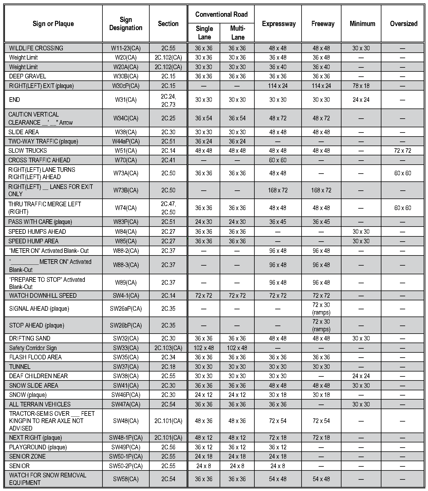
Table 2C-2. Minimum Size of Supplemental
| Size of Warning Sign | Size of Supplemental Plaque | |||
|---|---|---|---|---|
| Rectangular | Square | |||
| 1 Line | 2 Lines | Arrow | ||
| 24 x 24 | 24 x 12 | 24 x 18 | 21 x 15 | 18 x 18 |
| 30 x 30 | ||||
| 36 x 36 | 30 x 18 | 30 x 24 | 30 x 21 | 24 x 24 |
| 48 x 48 | ||||
Notes:
1. Larger supplemental plaques may be used when appropriate
2. Dimensions are shown as width x height, in inches
- 2. Dimensions are shown as width x height, in inches
Table 2C-3. Guidelines for Advance Placement of Warning Signs
| Posted or 85th- Percentile Speed | Advance Placement Distance1 | |||||||||
|---|---|---|---|---|---|---|---|---|---|---|
| Condition A: Speed reduction and lane changing in heavy traffic2 | Condition B: Deceleration to the listed advisory speed (mph) for the condition | |||||||||
| 03 | 104 | 204 | 304 | 404 | 504 | 604 | 704 | 804 | ||
| 20 mph | 225 ft | 115 ft | N/A5 | — | — | — | — | — | — | — |
| 25 mph | 325 ft | 155 ft | N/A5 | N/A5 | — | — | — | — | — | — |
| 30 mph | 460 ft | 200 ft | N/A5 | N/A5 | — | — | — | — | — | — |
| 35 mph | 565 ft | 250 ft | N/A5 | N/A5 | N/A5 | — | — | — | — | — |
| 40 mph | 670 ft | 305 ft | 100 ft6 | 100 ft6 | N/A5 | — | — | — | — | — |
| 45 mph | 775 ft | 360 ft | 125 ft | 100 ft6 | 100 ft6 | N/A5 | — | — | — | — |
| 50 mph | 885 ft | 425 ft | 200 ft | 175 ft | 125 ft | 100 ft6 | — | — | — | — |
| 55 mph | 990 ft | 495 ft | 275 ft | 225 ft | 200 ft | 125 ft | N/A5 | — | — | — |
| 60 mph | 1,100 ft | 570 ft | 350 ft | 325 ft | 275 ft | 200 ft | 100 ft6 | — | — | — |
| 65 mph | 1,200 ft | 645 ft | 450 ft | 400 ft | 350 ft | 275 ft | 200 ft | 100 ft6 | — | — |
| 70 mph | 1,250 ft | 730 ft | 525 ft | 500 ft | 450 ft | 375 ft | 275 ft | 150 ft | — | — |
| 75 mph | 1,350 ft | 820 ft | 625 ft | 600 ft | 550 ft | 475 ft | 375 ft | 250 ft | 100 ft6 | — |
| 80 mph | 1,475 ft | 910 ft | 725 ft | 700 ft | 625 ft | 550 ft | 450 ft | 350 ft | 200 ft | — |
| 85 mph | 1,600 ft | 1,010 ft | 825 ft | 800 ft | 750 ft | 675 ft | 575 ft | 450 ft | 300 ft | 150 ft |
1 The distances are adjusted for a sign legibility distance of 180 feet for Condition A. The distances for Condition B (with the exception of the potential stop condition) have been adjusted for a sign legibility distance of 250 feet, which is appropriate for an alignment warning symbol sign. For Conditions A and B, warning signs with less than 6-inch legend or more than four words, a minimum of 100 feet should be added to the advance placement distance to provide adequate legibility of the warning sign.
2 Typical conditions are locations where the road user must use extra time to adjust speed and change lanes in heavy traffic because of a complex driving situation. Typical signs are Merge and Right Lane Ends. The distances are determined by providing the driver a PRT of 14.0 to 14.5 seconds for vehicle maneuvers (2018 AASHTO Policy, Table 3-3, Decision Sight Distance, Avoidance Maneuver E) and adjusted for a legibility distance of 180 feet for the appropriate sign.
3 A typical condition is the warning of a potential stop situation. Typical signs are Stop Ahead, Yield Ahead, Signal Ahead, and Intersection Warning signs. The distances are based on the 2018 AASHTO Policy, Table 3-1, Stopping Sight Distance, providing a PRT of 2.5 seconds, a deceleration rate of 11.2 feet/second².
4 Typical conditions are locations where the road user must decrease speed to maneuver through the warned condition. Typical signs are Turn, Curve, Reverse Turn, or Reverse Curve. The distance is determined by providing a 2.5 second PRT, a vehicle deceleration rate of 10 feet/second², and adjusted for a sign legibility distance of 250 feet.
5 No suggested distances are provided for these speeds, as the placement location is dependent on site conditions and other signing. An alignment warning sign may be placed anywhere from the point of curvature up to 100 feet in advance of the curve. However, the alignment warning sign should be installed in advance of the curve and at least 100 feet from any other signs.
6 The minimum advance placement distance is listed as 100 feet to provide adequate spacing between signs.
Note: Warning signs that advise road users about conditions that are not related to a specific location, such as Deer Crossing or SOFT SHOULDER, can be installed in an appropriate location, based on engineering judgment.
Table 2C-4. Application of Traffic Control Devices for Changes in Horizontal Alignment
A - Determination of the Need for Devices for Changes in Horizontal Alignment1
| Roadway Type | AADT | |||
|---|---|---|---|---|
| Less than 1,000 | 1,000-2,999 | 3,000-3,999 | Greater than 3,999 | |
| Freeways and Expressways | Required | Required | Required | Required |
| Arterial or Collector without Pavement Markings | Optional | Recommended | Required | Required |
| Arterial or Collector with Pavement Markings2 | Optional | Recommended | Recommended | Required |
| All other roadways | Optional | Optional | Optional | Optional |
B - Selection of Devices for Changes in Horizontal Alignment
| Speed Differential3 | Devices for Change in Horizontal Alignment3 |
|---|---|
| 5 mph | Pavement markings or advance horizontal alignment warning sign on paved |
| roadways. Advance horizontal alignment warning sign on unpaved roadways.4 | |
| 10 mph | Advance horizontal alignment warning sign |
| 15 mph | Delineators5 and advance horizontal alignment warning sign |
| 20 mph or more | Chevrons5 and advance horizontal alignment warning sign |
3 The provisions for the use of Horizontal Alignment warning signs and devices are contained in Section 2C.06. The need for devices is determined by Chart A above.
4 A roadway is considered to have pavement markings when either a center line, edge lines, or both are present.
5 Section 2C.06 contains information about the use of a One Direction Large Arrow (W1-6) sign in place of or to supplement delineators and chevrons.
If devices are determined to be needed, the selection of the device(s) is based on Chart B below.
02. An arterial or collector is considered to have pavement markings when either a center line, edge lines, or both are present. B - Selection of Devices for Changes in Horizontal Alignment Pavement markings or advance horizontal alignment warning sign on paved roadways. Advance horizontal alignment warning sign on unpaved roadways. 4 Delineators5 and advance horizontal alignment warning sign Chevrons5 and advance horizontal alignment warning sign
03. The provisions for the use of Horizontal Alignment warning signs and devices are contained in Section 2C.06. The need for devices is determined by Chart A above.
04. A roadway is considered to have pavement markings when either a center line, edge lines, or both are present.
05. Section 2C.06 contains information about the use of a One Direction Large Arrow (W1-6) sign in place of or to supplement delineators and chevrons.
Table 2C-5. Typical Spacing of Chevron
| Advisory Speed | Curve Radius | Sign Spacing |
|---|---|---|
| 15 mph or less | Less than 200 feet | 40 feet |
| 20 to 30 mph | 200 to 400 feet | 80 feet |
| 35 to 45 mph | 401 to 700 feet | 120 feet |
| 50 to 60 mph | 701 to 1,250 feet | 160 feet |
| More than 60 mph | More than 1,250 feet | 200 feet |
Note: The relationship between the curve radius and the advisory speed shown in this table should not be used to determine the advisory speed.
Note: The relationship between the curve radius and the advisory speed shown in this table should not be used to determine the advisory
Table 2C-6. Use of Advisory Speed Plaque for Horizontal Alignment Changes
| Speed Differential | Use of Advisory Speed Plaque (W13-1P)1 |
|---|---|
| 5 mph | Optional |
| 10 mph | Recommended |
| 15 mph or more | Required |
1 See Section 2C.59
See Section 2C.59