4H. Bicycle Signals¶
§4H.01 Use of Bicycle Signal Faces¶
Option
01. A bicycle signal face may be used to provide separate control of a bicyclist movement for various situations, including the following:
- A. To provide a protected bicycle signal phase or a leading or lagging bicycle interval;
- B. To continue a through bicycle lane on the right-hand side of a mandatory right-turn lane (or on the left-hand side of a mandatory left-turn lane) that would otherwise be in non-compliance with Paragraph 1 of Section 9E.02 or Paragraph 7 of Section 9E.06;
- C. To provide a bicycle interval for a counter-flow bicycle facility; or
- D. To provide for unusual or unexpected arrangements of the bicyclist movement through complex intersections, conflict areas, or signal control.
02. A bicycle signal face may be used at a mid-block traffic control signal where there are no motor vehicle movements parallel to the bicycle crossing.
Support
03. Chapter 4C contains information on warrants for the installation of a new traffic control signal.
Guidance
04. The decision as to whether to incorporate a bicycle signal face(s) into a new traffic control signal design should be made during the engineering study performed in accordance with Paragraph 1 of Section 4C.01.
05. Engineering judgment should be exercised in determining whether or not it would be advantageous or beneficial to install a bicycle signal face(s) at an existing traffic control signal.
Support
06. Retrofitting existing circular traffic signals that are operated as bicycle signal faces with bicycle symbol signal faces is analogous to retrofitting existing traffic signals with pedestrian signals where such a determination is not required through an engineering study.
07. For the purpose of warrant analyses, provisions for classifying bicycles are provided in Paragraph 16 of Section 4C.01 and Paragraph 2 of Section 9F.01.
Standard
08. If used, a bicycle signal face shall only be used to control bicyclist movements from a designated bicycle lane or from a separate facility, such as a shared-use path.
09. If used, a bicycle signal face shall only be used to control bicyclist movements where bicyclists moving on a GREEN BICYCLE or YELLOW BICYCLE signal indication are not in conflict with any simultaneous motor vehicle movement at the signalized location, including right (or left) turns on red.
Guidance
10. If used where motor vehicle traffic can make the same movements as bicyclists, a bicycle signal face should only be used if the bicyclist movement controlled by the bicycle signal face is sometimes allowed to proceed or sometimes required to stop at times when motor vehicle traffic, making the same movement and controlled by other vehicular signal faces, is required to stop or allowed to proceed, respectively.
§4H.02 Prohibited Uses of Bicycle Signal Faces¶
Standard
01. Bicycle signal faces shall not be used to control conflicting bicyclist movements from perpendicular or nearly perpendicular directions.
Support
01a. As clarified by FHWA’s MUTCD Team, the purpose of this prohibition is intended to eliminate the “bike scramble” used in some jurisdictions that operate similar to a pedestrian scramble phase where all movements go at the same time from all directions. Since bicycles can be traveling much faster than pedestrians, the intent is to require separate phases to separate conflicting bicycle movements from perpendicular or near perpendicular directions.
Standard
02. Bicycle signal faces shall not be used for controlling any bicyclist movement that is sharing an approach lane with motor vehicle traffic.
03. Bicycle signal faces shall not be used in any manner with respect to the design and operation of a hybrid beacon.
§4H.03 Bicycle Signal Signs¶
Support
01. The primary purposes of the Bicycle Signal (R10-40, R10-40a, R10-41, R10-41a, R10-41b) sign (see Section 9B.22) are to inform road users that the signal indications in the bicycle signal face are intended only for bicyclists, and to inform bicyclists which specific bicyclist movements are controlled by the bicycle signal face.
Standard
02. Except as provided in Paragraph 3 of this Section, a Bicycle Signal (R10-40, R10-40a, R10-41, R10-41a, or R10-41b) sign shall be installed immediately adjacent to (including above or below) every bicycle signal face. The Bicycle Signal sign shall have a minimum size of 24 inches x 36 inches if it is placed next to an overhead-mounted bicycle signal face and shall have a minimum size of 12 inches x 21 inches if it is placed next to a post-mounted bicycle signal face.
Support
02a. Refer to FHWA’s List of Known Errors for error in Paragraph 2 text. Refer to Section 1A.04 for more details.
Option
03. The Bicycle Signal sign may be omitted adjacent to a supplemental near-side bicycle signal face containing 4-inch indications.
§4H.04 Application of Bicycle Symbol Signal Indications during Steady (Stop-and-Go) Operation¶
Standard
Steady bicycle symbol signal indications shall be applied as follows:
- A. A steady RED BICYCLE signal indication shall be displayed when it is intended to prohibit bicyclists in a designated bicycle lane or from a separate facility such as a shared-use path from entering the intersection or other controlled area. Turning after stopping shall be permitted as stated in Item C in Paragraph 1 of Section 4A.05.
- B. A steady YELLOW BICYCLE signal indication shall be displayed following a GREEN BICYCLE signal indication in the same bicycle signal face. A YELLOW BICYCLE signal indication shall not be displayed in conjunction with the change from the RED BICYCLE signal indication to a GREEN BICYCLE signal indication. The YELLOW BICYCLE signal indication shall be followed by a RED BICYCLE signal indication.
- C. A steady GREEN BICYCLE signal indication shall be displayed only when it is intended to permit bicyclists in a designated bicycle lane or from a separate facility such as a shared-use path to enter the intersection as discussed in Section 4A.05.
§4H.05 Application of Bicycle Symbol Signal Indications during Flashing Operation¶
Standard
01. The mode of operation of the bicycle signal faces at a traffic control signal shall be the same as the mode of operation of the other traffic signal faces at the same signalized location. Bicycle signal faces shall operate in the steady (stop-and-go) mode when the other traffic signal faces are operating in the steady (stop-and-go) mode. Bicycle signal faces shall operate in the flashing mode when the other signal faces are operating in the flashing mode. Bicycle signal faces shall not be placed in a dark mode when other vehicular traffic signal faces are operating in the flashing mode.
Guidance
02. When a traffic control signal is operated in the flashing mode, bicycle signal faces should display a flashing RED BICYCLE signal indication if the other vehicular signal faces on the same approach are displaying flashing red signal indications or if there are no other vehicular signal faces on the same approach.
03. When a traffic control signal is operated in the flashing mode, bicycle signal faces should display a flashing YELLOW BICYCLE signal indication if the other vehicular signal faces for the through lanes on the same approach are displaying flashing yellow signal indications unless it is determined by engineering judgment that a flashing RED BICYCLE signal indication would provide a safer operation.
Support
Refer to National MUTCD website, Frequently Asked Questions (FAQs) on Part 4 – Highway Traffic Signals, for use of flashing yellow Bicycle Symbol Signal Indication. Refer to Section 1A.04 for more details.
§4H.06 Layout of Bicycle Signal Faces¶
Standard
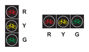
01. Bicycle signal faces shall consist of all bicycle symbol signal indications (see Figure 4H-1). Circular or arrow signal indications shall not be used in a bicycle signal face.
Option
02. Bicycle signal faces may be oriented vertically or horizontally.
Standard
03. The layouts and arrangements of the bicycle signal face shall be in accordance with the following provisions:
- A. Only the bicycle symbol shown on Page 6-7 in the 2004 Standard Highway Signs publication (see Section 1A.05) shall be used for bicycle symbol signal indications and shall be proportioned to fit within the signal lens. The bicycle symbol shall only be positioned horizontally and shall face to the left.
- B. The RED BICYCLE, YELLOW BICYCLE, and GREEN BICYCLE signal indications shall be in the same relative position to each other as specified for the CIRCULAR RED, CIRCULAR YELLOW, and CIRCULAR GREEN signal indications, respectively, in Sections 4E.04 and 4E.05.
- C. As a specific exception to Paragraph 5 of Section 4E.04, two YELLOW BICYCLE signal indications or two GREEN BICYCLE signal indications shall not be arranged horizontally adjacent to each other at right angles to the basic straight line arrangement to form a clustered signal face.
Option
04. Backplates (see Paragraphs 18 and 19 in Section 4D.06) may be used with bicycle signal faces.
05. If a bicycle signal face having 4-inch signal indications is used, the accompanying visors may be omitted.
§4H.07 Size of Bicycle Symbol Signal Indications¶
Standard
01. There shall be three nominal diameter sizes for bicycle signal indications: 4 inches, 8 inches, and 12 inches.
02. All signal indications in a bicycle signal face shall be of the same size.
03. Four-inch signal indications shall not be used for any bicycle signal face other than a supplemental, post-mounted, near-side bicycle signal face.
§4H.08 Placement of Bicycle Signal Faces¶
Standard
01. The provisions of Sections 4D.05 through 4D.08 shall apply to the placement of the bicycle signal faces except as follows:
- A. As a specific exception to Item A in Paragraph 1 of Section 4D.05, a minimum of one primary bicycle signal face shall be provided to control traffic for the bicyclist movement, even if a bicyclist through movement exists.
- B. The primary bicycle signal face shall have either 8-inch or 12-inch signal indications, even if it is located at the near side of the signal-controlled location.
- C. When the primary bicycle signal face is located more than 120 feet beyond the stop line, a supplemental near-side bicycle signal face shall be provided.
Guidance
02. When the primary bicycle signal face is located more than 80 feet and up to 120 feet beyond the stop line, a supplemental near-side bicycle signal face should be provided.
03. A bicycle signal face should be separated horizontally or vertically from the nearest vehicular traffic signal face for the same approach by at least 3 feet measured either horizontally perpendicular to the approach between the centers of the signal faces or vertically from the center of the lowest signal indication of the top signal face to the center of the highest signal indication of the bottom signal face. If horizontally- arranged or clustered signal faces are used, the minimum 3-foot horizontal separation between the two signal faces should be measured from the center of the rightmost signal indication in the signal face on the left to the center of the left-most signal indication in the signal face on
04. the right. Bicycle signal faces should be placed such that visibility is maximized for bicyclists and minimized for adjacent or conflicting vehicle movements not controlled by the bicycle signal face. Consideration should be given to using visibility-limited bicycle signal faces in situations where drivers not controlled by the bicycle signal face might be confused by viewing the bicycle signal indications, such as when the bicyclist movement controlled by the bicycle signal face is sometimes allowed to proceed or sometimes required to stop at times when motor vehicle traffic, making the same movement and controlled by other vehicular signal faces, is required to stop or allowed to proceed, respectively.
§4H.09 Mounting Height of Bicycle Signal Faces¶
Standard
The provisions of Section 4D.09 shall apply to the mounting height of bicycle signal faces except as follows:
- A. The bottom of the signal housing (including brackets) of a bicycle signal face that is not located over a roadway or shoulder shall be a minimum of 7 feet above the sidewalk or ground, and
- B. If 4-inch signal indications are used in a supplemental, post-mounted, near-side bicycle signal face, the bottom of the signal housing (including brackets) shall be a minimum of 4 feet and a maximum of 8 feet above the sidewalk or ground. Bicycle signal faces with 4-inch signal indications installed above a pedestrian sidewalk or pathway shall not project more than 4 inches into the pedestrian facility.
§4H.10 Intensity and Light Distribution of Bicycle Signal Faces¶
Guidance
Except for the 4-inch nominal size of the lens diameter, the intensity and distribution of light from each illuminated bicycle signal face should be similar to that recommended for vehicular traffic signal faces in accordance with Paragraph 11 of Section 4E.01 to the extent practical.
§4H.11 Yellow Change and Red Clearance Intervals for Bicycle Signal Faces¶
Standard
01. The provisions of Section 4F.17 shall apply to the duration of the yellow change and the red clearance intervals of a bicycle signal phase.
Guidance
02. The minimum duration of the yellow change interval of a bicycle signal phase should be 3 seconds.
Support
03. The function of the yellow change interval is to warn bicyclists approaching a signalized location that their permission to proceed is being terminated after which they will be directed to stop. Providing clearance time for a bicyclist to travel through the intersection or conflict area is the purpose of the red clearance interval rather than the yellow change interval.
§4H.12 Bicycle Push Buttons¶
Option
01. Bicycle push buttons may be used for bicycle detection. Support:
02. The location of bicycle push buttons intended only for use by bicyclists and not pedestrians are determined by engineering judgment considering a reasonable reach without requiring most bicyclists to dismount.
Standard
03. Where used, push buttons intended to be used by both pedestrians and bicyclists shall be located and operated to meet all accessibility requirements (see Section 4I.05).
04. Bicycle push buttons shall be accompanied by an appropriate regulatory sign (R10-4, R10-24, or R10-26) explaining the purpose and operation of the push button (see Sections 2B.58 and 9B.20).
§4H.101(CA) Optional Use of Bicycle Signal Faces¶
Support
01. A bicycle signal (refer to Figure 4H-1) is an electrically powered traffic control device that uses bicycle signal faces and directs bicyclists to take specific actions. Use of bicycle signal faces is analogous to using pedestrian signal heads where implementation is based on engineering judgment. Refer to CVC §§ 21450 and 21456.3.
Option
02. Existing signalized locations may be retrofitted with additional signal heads that include bicycle signal faces if the engineer determines that it would be advantageous or beneficial to have the signalized location implement bicycle signal faces.
Standard
03. If used, bicycle signal faces shall only be used at signalized locations. Signal phasing shall be such that while bicycles are moving on a green or yellow bicycle indication, they are not in conflict with any simultaneous motor vehicle movements at the signalized location, including right (or left) turns on red.
Guidance
04. Before existing signalized intersections are retrofitted with bicycle signal faces, alternative means of handling conflicts between bicycles and motor vehicles should be considered.
05. Two alternatives that should be considered are:
- A. Striping to direct a bicyclist to a lane adjacent to a traffic lane such as a bike lane to left of a right-turn-only lane.
- B. Redesigning the intersection to direct a bicyclist from an off-street path to a bicycle lane at a point removed from the signalized intersection.
§4H.102(CA) Limit Line Bicycle Detection Zone¶
Standard
All new limit line bicycle detection zone installations and modifications to the existing limit line bicycle detection zone installations on a public or private road or driveway intersecting a public road (refer to Section 1B.01 for applicability and Section 1C.02 for definitions and meanings) shall either provide a Limit Line Bicycle Detection Zone in which the Reference Bicycle-Rider for each traffic movement from each approach is detected or be placed on permanent recall or fixed time operation. Refer to CVC § 21450.5.
02. All new and modified bike path approaches to a signalized intersection shall be equipped with either a Limit Line Bicycle Detection Zone or a bicyclist pushbutton, or else the phase serving the bike path shall be placed on permanent recall or fixed time operation. A bicyclist pushbutton, if used, shall be located on the right side of the bike path and where it can be reached from the bike path.
03. At new signalized intersections or when the advance detection is being replaced at existing signalized intersections, phases with advance detection only shall be placed on permanent recall.
Support
04. The requirement to detect the Reference Bicycle-Rider in the Limit Line Bicycle Detection Zone is technology-neutral.
Option
05. The limit line bicycle detection zone in a bike lane may be narrower than 6 feet. Refer to Figure 4H-101(CA).
06. A Bicycle Detector Symbol may be used. Refer to Sections 9B.20 and 9E.15.
07. A bicyclist pushbutton may be used to supplement the required limit line bicycle detection zone.
Support
08. Refer to Chapter 9B for bicycle regulatory signs and Chapter 9E for bicycle facility markings.
Guidance
09. If more than 50% of the limit line detectors need to be replaced at a signalized intersection, then the entire intersection should be upgraded so that every lane has a Limit Line Bicycle Detection Zone.
10. The Reference Bicycle-Rider or the equivalent should be used to confirm bicycle detection under the following situations:
- A. A new detection system has been installed; or
- B. The detection configuration has been modified.
Support
11. CVC § 21202(a) requires bicyclists traveling “at a speed less than the normal speed of traffic” to ride “as close as practicable to the right-hand curb or edge of the roadway” with exceptions, including when the bicyclist is “approaching a place where a right turn is authorized.” This exception was intended to provide the bicyclist the flexibility to avoid having to ride against the right hand curb or edge of the road where a potential conflict would be created with a right turning road user.
12. A Limit Line Bicycle Detection Zone provides for the detection of both bicycles and vehicles, including motorcycles.
Guidance
13. Where a Limit Line Bicycle Detection Zone that detects the Reference Bicycle-Rider has been provided, minimum bicycle timing should be provided as follows:
14. For all phases, the sum of the minimum green, plus the yellow change interval, plus any red clearance interval should be
01. sufficient to allow a bicyclist riding a bicycle 6 feet long to clear the last conflicting lane at a speed of 14.7 feet/sec plus an additional effective start-up time of 6 seconds, according the formula Gmin + Y + Rclear ≥ 6 sec + (W+6 feet)/14.7 feet/sec, Where: Gmin = Length of minimum green interval (sec) Y = Length of yellow interval (sec) Rclear = Length of red clearance interval (sec) W = Distance from limit line to far side of last conflicting lane (feet)
Support
15. Bicyclist crossing times are shown in Table 4H-101(CA). The speed of 14.7 feet/sec represents the final crossing speed and the effective start-up time of 6 seconds represents the time lost in reacting to the green light and then accelerating to full speed.
Option
16. A limit line bicycle detection system that can discriminate between bicyclists and vehicles may be used to extend the length of the minimum green.
17. Supplemental Reference Bicycle-Rider detection zones, new technology, or various signal controller settings may be utilized to adjust the time (Gmin + Y + Rclear ) and/or travel distance (W) that bicyclists are exposed to conflicting vehicular traffic.
-sheet1.png)
Signs shown: R10-26
- B. Intersection with a Bike Lane and Right-turn Lane
- A. Intersection with a Wide Right/Through Lane
04. The detection zone in a bike lane may be narrower than 6’.
01. PUSH BUTTON (Optional)
03. NOT TO SCALE
- 1. Typical technology-neutral limit line detection locations. See Section 4H.102(CA).
- 2. Typical presence detection locations.
- 3. Typical advance detection locations.
- 4. A bicyclist pushbutton may be used to activate a traffic signal to supplement the required limit line detection. A pushbutton should be located so it is convenient to use by bicyclists. See Chapter 9B for bicycle regulatory signs.
-sheet2.png)
Signs shown: R10-26
- C. Intersection with a Bike Lane Striped to the Intersection
- D. Intersection with a Bike Lane Dropped before the Intersection
04. PUSH BUTTON (Optional) (Optional)
03. NOT TO SCALE
- 1. Typical technology-neutral limit line detection locations. See Section 4H.102(CA).
- 2. Typical presence detection locations.
- 3. Typical advance detection locations.
- 4. A bicyclist pushbutton may be used to activate a traffic signal to supplement the required limit line detection. A pushbutton should be located so it is convenient to use by bicyclists. See Chapter 9B for bicycle regulatory signs.
-sheet3.png)
Signs shown: R10-26
- F. Intersection with a Channelized Right-turn Lane
- E. Intersection with a Bike Lane, a Share Right/Through Lane and Channelizing Island
04. R10-26 (Optional) (Optional)
03. NOT TO SCALE
- 1. Typical technology-neutral limit line detection locations. See Section 4H.102(CA).
- 2. Typical presence detection locations.
- 3. Typical advance detection locations.
- 4. A bicyclist pushbutton may be used to activate a traffic signal to supplement the required limit line detection. A pushbutton should be located so it is convenient to use by bicyclists. See Chapter 9B for bicycle regulatory signs.
Table 4H-101(CA). Signal Operations - Minimum Bicycle Timing
| 𝐺 + Y + 𝑅 ≥ 6 Sec + (w+6 ft)/14.7 ft/Sec, Where 𝑚𝑖𝑛 𝑐𝑙𝑒𝑎𝑟 | |
|---|---|
| 𝐺 = Length of minimum green interval (sec) 𝑚𝑖𝑛 | |
| Y = Length of yellow interval (sec) | |
| 𝑅 = Length of red clearance interval (sec) 𝑐𝑙𝑒𝑎𝑟 | |
| W = distance from limit line to far side of last conflicting lane (ft) | |
| Distance from limit line to far side of last conflicting lane | Minimum phase length (minimum green plus yellow plus red clearance) |
| Feet | Seconds |
| 40 | 9.1 |
| 50 | 9.8 |
| 60 | 10.5 |
| 70 | 11.2 |
| 80 | 11.9 |
| 90 | 12.5 |
| 100 | 13.2 |
| 110 | 13.9 |
| 120 | 14.6 |
| 130 | 15.3 |
| 140 | 15.9 |
| 150 | 16.6 |
| 160 | 17.3 |
| 170 | 18.0 |
| 180 | 18.7 |
𝐺𝑚𝑖𝑛 + Y + 𝑅𝑐𝑙𝑒𝑎𝑟 ≥ 6 Sec + (w+6 ft)/14.7 ft/Sec, Where 𝐺𝑚𝑖𝑛 = Length of minimum green interval (sec) Y = Length of yellow interval (sec) 𝑅𝑐𝑙𝑒𝑎𝑟 = Length of red clearance interval (sec) W = distance from limit line to far side of last conflicting lane (ft) Distance from limit line to far side of