2B. Regulatory Signs¶
Chapter 2B. REGULATORY SIGNS, BARRICADES, AND GATES¶
§2B.01 Application of Regulatory Signs¶
Standard
01. Regulatory signs shall be used to inform road users of selected traffic laws or regulations and to indicate the applicability of the legal requirements.
02. Regulatory signs shall be installed at or near where the regulations apply. The signs shall clearly indicate the requirements imposed by the regulations and shall be designed and installed to provide adequate visibility and legibility in order to obtain compliance.
03. Regulatory signs shall be retroreflective or illuminated (see Section 2A.21).
§2B.02 Design of Regulatory Signs¶
Standard
01. Regulatory signs shall be rectangular unless specifically designated otherwise in this Manual. Regulatory signs shall be designed in accordance with the sizes, shapes, colors, and legends contained in the “Standard Highway Signs” publication (see Section 1A.05).
Support
02. The use of educational plaques to supplement symbol signs is described in Section 2A.09.
03. The use of LEDs in the border or legend of regulatory signs is described in Section 2A.12.
Standard
04. LED signs displaying a part-time prohibitory message incorporating a red circle and diagonal of a static sign shall display a red symbol that approximates the same red circle and diagonal as closely as possible. The symbol of the action to be prohibited shall be displayed in white LEDs on a black background.
05. A regulatory sign displayed entirely with LEDs and incorporated within the border of a larger full-matrix changeable message sign shall display the regulatory sign legend in the size, shape, color, and legend of the standard regulatory sign.
§2B.03 Size of Regulatory Signs¶
Standard
01. Except as provided in Section 2A.07, the minimum sizes for regulatory signs shall be as shown in Table 2B-1.
Support
02. Section 2A.07 contains information regarding the applicability of the various columns in Table 2B-1.
Standard
03. Except as provided in Paragraphs 5 and 6 of this Section, the minimum sizes for regulatory signs facing traffic on multi-lane conventional roads shall be as shown in the Multi-Lane column of Table 2B-1.
04. The minimum size of regulatory signs applied on low-volume rural roads with operating speeds of 30 mph or less shall be as shown in the Minimum column of Table 2B-1.
Option
05. Where the posted speed limit is 35 mph or less on a multi-lane highway or street, other than for a STOP sign, the minimum size shown in the Single Lane column in Table 2B-1 may be used.
06. Where a regulatory sign, other than a STOP sign, is placed on the left-hand side of a multi-lane roadway in addition to the installation of the same regulatory sign on the right-hand side or the roadway, the minimum size shown in the Single Lane column in Table 2B-1 may be used for both the sign on the right-hand side and the sign on the left-hand side of the roadway.
Guidance
07. The minimum sizes for regulatory signs facing traffic on exit and entrance ramps at major interchanges connecting an Expressway or Freeway with an Expressway or Freeway (see Section 2E.11) should be as shown in the column of Table 2B-1 that corresponds to the mainline roadway classification (Expressway or Freeway). If a minimum size is not provided in the Freeway column, the minimum size in the Expressway column should be used. If a minimum size is not provided in the Freeway or Expressway Column, the size in the Oversized column should be used.
08. The minimum sizes for all regulatory signs facing traffic on exit and entrance ramps at all other classifications of interchanges (see Section 2E.11) should be the sizes shown in Table 2B-1 in the Conventional Road Single Lane column for single-lane ramps and in the Multi-Lane column for multi-lane ramps.
Table 2B-1. Regulatory Sign and Plaque Sizes (Sheet 1 of 6)
| Sign or Plaque | Sign Designation | Section | Conventional Road | Expressway | Freeway | Minimum | Oversized | |
|---|---|---|---|---|---|---|---|---|
| Single Lane | Multi-Lane | |||||||
| Stop | R1-1 | 2B.04 | 30 x 30 | 36 x 36 | 36 x 36 | — | 30 x 30* | 48 x 48 |
| Yield | R1-2 | 2B.05 | 36 x 36 x 36 | 48 x 48 x 48 | 48 x 48 x 48 | 60 x 60 x 60 | 30 x 30 x 30* | — |
| To Oncoming Traffic (plaque) | R1-2aP | 2B.18 | 24 x 18 | 24 x 18 | 36 x 30 | 48 x 36 | 24 x 18 | — |
| To Traffic in Circle (plaque) | R1-2bP | 2B.18 | 24 x 15 | 24 x 15 | — | — | 24 x 15 | 36 x 24 |
| To All Lanes (plaque) | R1-2cP | 2B.18 | 24 x 15 | 24 x 15 | — | — | 24 x 15 | 36 x 24 |
| All Way (plaque) | R1-3P | 2B.04 | 18 x 6 | 18 x 6 | — | — | — | 30 x 12 |
| Yield Here to Pedestrians | R1-5 | 2B.19 | — | 36 x 36 | — | — | — | 36 x 36 |
| Stop Here for Pedestrians | R1-5b | 2B.19 | — | 36 x 36 | — | — | — | 36 x 36 |
| Yield Here to (Stop Here for) Trail Crossing | R1-5d,5e | 2B.19 | — | 36 x 42 | — | — | — | — |
| In-Street Pedestrian Crossing - Yield (Stop) | R1-6,6a | 2B.20 | 12 x 36 | 12 x 36 | — | — | — | — |
| In-Street Trail Crossing - Yield (Stop) | R1-6d,6e | 2B.20 | 12 x 36 | 12 x 36 | — | — | — | — |
| Overhead Pedestrian Crossing - Yield (Stop) | R1-9,9a | 2B.20 | 90 x 24 | 90 x 24 | — | — | — | — |
| Overhead Trail Crossing | R1-9d,9e | 2B.20 | 72 x 24 | 72 x 24 | — | — | — | — |
| Except Right Turn (plaque) | R1-10P | 2B.04 | 24 x 18 | 24 x 18 | — | — | — | — |
| Speed Limit | R2-1 | 2B.21 | 24 x 30 | 30 x 36 | 36 x 48 | 48 x 60 | 18 x 24 | 30 x 36 |
| Truck Speed Limit (plaque) | R2-2P | 2B.22 | 24 x 24 | 24 x 24 | 36 x 36 | 48 x 48 | — | 36 x 36 |
| Bus Speed Limit (plaque) | R2-2aP | 2B.22 | 24 x 24 | 24 x 24 | 36 x 36 | 48 x 48 | — | 36 x 36 |
| Truck-Bus Speed Limit (plaque) | R2-2bP | 2B.22 | 24 x 30 | 24 x 30 | 36 x 42 | 48 x 54 | — | 36 x 42 |
| Vehicles Over X Tons Speed Limit (plaque) | R2-2cP | 2B.22 | 24 x 30 | 24 x 30 | 36 x 42 | 48 x 54 | — | 36 x 42 |
| Night Speed Limit (plaque) | R2-3P | 2B.23 | 24 x 24 | 24 x 24 | 36 x 36 | 48 x 48 | — | 36 x 36 |
| Minimum Speed Limit (plaque) | R2-4P | 2B.24 | 24 x 24 | 24 x 24 | 36 x 36 | 48 x 48 | — | 36 x 36 |
| Combined Maximum and Minimum Speed Limits | R2-4a | 2B.24 | 24 x 48 | 24 x 48 | 36 x 72 | 48 x 96 | — | 36 x 72 |
| Unless Otherwise Posted (plaque) | R2-5P | 2B.21 | 24 x 18 | 24 x 18 | 36 x 24 | 36 x 24 | — | 36 x 24 |
| Citywide (plaque) | R2-5aP | 2B.21 | 24 x 6 | 24 x 6 | — | — | — | 30 x 9 |
| Neighborhood (plaque) | R2-5bP | 2B.21 | 24 x 6 | 24 x 6 | — | — | — | 30 x 9 |
| Residential (plaque) | R2-5cP | 2B.21 | 24 x 6 | 24 x 6 | — | — | — | 30 x 9 |
| Fines Higher (plaque) | R2-6P | 2B.25 | 24 x 18 | 24 x 18 | 36 x 24 | 48 x 36 | — | 36 x 24 |
| Fines Double (plaque) | R2-6aP | 2B.25 | 24 x 18 | 24 x 18 | 36 x 24 | 48 x 36 | — | 36 x 24 |
| $XX Fine (plaque) | R2-6bP | 2B.25 | 24 x 18 | 24 x 18 | 36 x 24 | 48 x 36 | — | 36 x 24 |
| Begin Higher Fines Zone | R2-10 | 2B.25 | 24 x 30 | 24 x 30 | 36 x 48 | 48 x 60 | — | 36 x 48 |
| End Higher Fines Zone | R2-11 | 2B.25 | 24 x 30 | 24 x 30 | 36 x 48 | 48 x 60 | — | 36 x 48 |
| End Variable Speed Limit | R2-13 | 2B.21 | 24 x 30 | 24 x 30 | 36 x 48 | 48 x 60 | — | 36 x 48 |
| End Truck Speed Limit | R2-14 | 2B.21 | 24 x 30 | 24 x 30 | 36 x 48 | 48 x 60 | — | 36 x 48 |
| Movement Prohibition | R3-1,2,3, 4,18,27 | 2B.26 | 24 x 24 | 36 x 36 | 36 x 36 | — | — | 48 x 48 |
| Movement Prohibition - Trucks | R3-1b | 2B.26 | 24 x 36 | 24 x 36 | 36 x 54 | 36 x 54 | — | — |
| Movement Prohibition - Trucks Buses | R3-1c | 2B.26 | 24 x 42 | 24 x 42 | 36 x 60 | 36 x 60 | — | — |
| Movement Prohibition - Trucks Over X Tons | R3-1d | 2B.26 | 24 x 48 | 24 x 48 | 36 x 66 | 36 x 66 | — | — |
| Movement Prohibition - Except Buses | R3-1e | 2B.26 | 24 x 36 | 24 x 36 | 36 x 54 | 36 x 54 | — | — |
| Movement Prohibition - Except Buses Taxis | R3-1f | 2B.26 | 24 x 42 | 24 x 42 | 36 x 66 | 36 x 66 | — | — |
| Movement Prohibition - Time and Day | R3-1g | 2B.26 | 24 x 36 | 24 x 36 | 36 x 54 | 36 x 54 | — | — |
Table 2B-1. Regulatory Sign and Plaque Sizes (Sheet 2 of 6)
| Sign or Plaque | Sign Designation | Section | Conventional Road | Expressway | Freeway | Minimum | Oversized | |
|---|---|---|---|---|---|---|---|---|
| Single Lane | Multi-Lane | |||||||
| Movement Prohibition - Multiple Times and Day | R3-1h | 2B.26 | 24 x 42 | 24 x 42 | 36 x 66 | 36 x 66 | — | — |
| Mandatory Movement Lane Control | R3-5,5a | 2B.28 | 30 x 36 | 30 x 36 | — | — | — | — |
| Left Lane (plaque) | R3-5bP | 2B.28 | 30 x 12 | 30 x 12 | — | — | — | — |
| HOV 2+ (plaque) | R3-5cP | 2B.28 | 24 x 12 | 24 x 12 | — | — | — | — |
| Taxi Lane (plaque) | R3-5dP | 2B.28 | 30 x 12 | 30 x 12 | — | — | — | — |
| Right Lane (plaque) | R3-5fP | 2B.28 | 30 x 12 | 30 x 12 | — | — | — | — |
| Bus Lane (plaque) | R3-5gP | 2B.28 | 30 x 12 | 30 x 12 | — | — | — | — |
| Optional Movement Lane Control Thru and Turn | R3-6 | 2B.29 | 30 x 36 | 30 x 36 | — | — | — | — |
| Optional Movement U and Left Turn | R3-6a | 2B.29 | 30 x 36 | 30 x 36 | — | — | — | — |
| Optional Movement Left Turns | R3-6b | 2B.29 | 30 x 36 | 30 x 36 | — | — | — | — |
| Right (Left) Lane Must Turn Right (Left) | R3-7 | 2B.28 | 30 x 30 | 36 x 36 | 48 x 48 | — | — | 48 x 48 |
| Except Buses (plaque) | R3-7aP | 2B.28 | 24 x 12 | 24 x 12 | — | — | — | — |
| Except Bicycles (plaque) | R3-7bP | 2B.28 | 24 x 12 | 24 x 12 | — | — | — | — |
| Advance Intersection Lane Control | R3-8,8a,8b, 8xa, 8xb,8xc | 2B.30 | Varies x 30 | Varies x 30 | — | — | — | Varies x 36 |
| Advance Circular Intersection Lane Control (2 Lanes) | R3-8zd, R3-8ze, R3-8zf, R3-8zg | 2B.27 | — | 36 x 36 | — | — | — | — |
| Two-Way Left Turn Only (overhead) | R3-9a | 2B.32 | 30 x 36 | 30 x 36 | — | — | — | — |
| Two-Way Left Turn Only (post-mounted) | R3-9b | 2B.32 | 24 x 36 | 24 x 36 | — | — | — | 36 x 48 |
| Begin (plaque) | R3-9cP | 2B.33 | 24 x 12 | 24 x 12 | — | — | — | 36 x 18 |
| End (plaque) | R3-9dP | 2B.33 | 24 x 12 | 24 x 12 | — | — | — | 36 x 18 |
| Reversible Lane Control (overhead) | R3-9e | 2B.34 | 108 x 48 | 108 x 48 | — | — | — | — |
| Reversible Lane Control (post-mounted) | R3-9f | 2B.34 | 30 x 42 | 36 x 54 | — | — | — | — |
| Advance Reversible Lane Control Transition | R3-9g,9h | 2B.34 | 108 x 36 | 108 x 36 | — | — | — | — |
| End Reverse Lane | R3-9i | 2B.34 | 108 x 48 | 108 x 48 | — | — | — | — |
| Lane For Left Turn Only | R3-19 | 2B.28 | 30 x 24 | 30 x 24 | — | — | — | — |
| Lane for U Turn Only | R3-19a | 2B.28 | 30 x 24 | 30 x 24 | — | — | — | — |
| Lane For U and Left Turns Only | R3-19b | 2B.28 | 30 x 30 | 30 x 30 | — | — | — | — |
| Begin Right (Left) Turn Lane | R3-20 | 2B.28 | 24 x 36 | 24 x 36 | — | — | — | — |
| All Turns (U-Turn) from Right Lane | R3-23,23a | 2B.35 | 60 x 36 | 60 x 36 | — | — | — | — |
| All Turns (U-Turn) Directional | R3-24,24b, 25,25b,26a | 2B.35 | 72 x 18 | 72 x 18 | — | — | — | — |
| U-Turns and Left Turns Directional | R3-24a, 25a,26 | 2B.35 | 60 x 24 | 60 x 24 | — | — | — | — |
| Right (Left) Lane Must Exit | R3-33 | 2B.31 | — | — | 78 x 36 | 78 x 36 | — | — |
| Right (Left) Lane Must Exit | R3-33a | 2B.31 | — | — | 42 x 60 | 42 x 60 | — | — |
| Do Not Pass | R4-1 | 2B.36 | 24 x 30 | 24 x 30 | 36 x 48 | 48 x 60 | 18 x 24* | 36 x 48 |
| Pass With Care | R4-2 | 2B.37 | 24 x 30 | 24 x 30 | 36 x 48 | 48 x 60 | 18 x 24* | 36 x 48 |
| Slower Traffic Keep Right | R4-3 | 2B.38 | 24 x 30 | 24 x 30 | 36 x 48 | 48 x 60 | 18 x 24* | 36 x 48 |
| Trucks Use Right Lane | R4-5 | 2B.38 | 24 x 30 | 24 x 30 | 36 x 48 | 48 x 60 | — | 36 x 48 |
| Keep Right | R4-7,7a,7b | 2B.39 | 24 x 30 | 24 x 30 | 36 x 48 | 48 x 60 | 18 x 24* | 36 x 48 |
| Narrow Keep Right | R4-7c | 2B.39 | 18 x 30 | 18 x 30 | — | — | — | — |
| Keep Left | R4-8,8a,8b | 2B.39 | 24 x 30 | 24 x 30 | 36 x 48 | 48 x 60 | 18 x 24 | 36 x 48 |
| Narrow Keep Left | R4-8c | 2B.39 | 18 x 30 | 18 x 30 | — | — | — | — |
| Stay in Lane | R4-9 | 2B.40 | 24 x 30 | 24 x 30 | 36 x 48 | 48 x 60 | 18 x 24 | 36 x 48 |
| Runaway Vehicles Only | R4-10 | 2B.41 | 48 x 48 | 48 x 48 | — | — | — | — |
Table 2B-1. Regulatory Sign and Plaque Sizes (Sheet 3 of 6)
| Sign or Plaque | Sign Designation | Section | Conventional Road | Expressway | Freeway | Minimum | Oversized | |
|---|---|---|---|---|---|---|---|---|
| Single Lane | Multi-Lane | |||||||
| Slow Vehicles with XX or More Following Vehicles Must Use Turn-Out | R4-12 | 2B.42 | 42 x 24 | 42 x 24 | — | — | — | 72 x 42 |
| Slow Vehicles Must Use Turn-Out Ahead | R4-13 | 2B.42 | 42 x 24 | 42 x 24 | — | — | — | — |
| Slow Vehicles Must Turn Out | R4-14 | 2B.42 | 30 x 42 | 30 x 42 | — | — | — | — |
| Keep Right Except to Pass | R4-16 | 2B.38 | 24 x 30 | 24 x 30 | 36 x 48 | 48 x 60 | 18 x 24* | 36 x 48 |
| Do Not Drive on Shoulder | R4-17 | 2B.43 | 24 x 30 | 24 x 30 | 36 x 48 | 48 x 60 | 18 x 24 | 36 x 48 |
| Do Not Pass on Shoulder | R4-18 | 2B.43 | 24 x 30 | 24 x 30 | 36 x 48 | 48 x 60 | 18 x 24 | 36 x 48 |
| All Traffic | R4-20 | 2B.44 | 24 x 30 | 24 x 30 | 36 x 48 | 48 x 60 | — | 36 x 48 |
| Right (Left) Turn Only | R4-21 | 2B.44 | 24 x 30 | 24 x 30 | — | — | — | — |
| Do Not Enter | R5-1 | 2B.46 | 30 x 30 | 36 x 36 | 36 x 36 | 48 x 48 | — | 36 x 36 |
| Wrong Way | R5-1a | 2B.47 | 36 x 24 | 42 x 30 | 36 x 24 | 42 x 30 | 30 x 18 | 42 x 30 |
| No Trucks | R5-2 | 2B.45 | 24 x 24 | 24 x 24 | 30 x 30 | 36 x 36 | — | 36 x 36 |
| Except Local Deliveries (plaque) | R5-2aP | 2B.45 | 24 x 12 | 24 x 12 | 30 x 15 | 36 x 18 | — | 36 x 18 |
| No Thru Trucks | R5-2b | 2B.45 | 24 x 30 | 24 x 30 | 30 x 36 | 36 x 48 | — | 36 x 48 |
| No Motor Vehicles | R5-3 | 2B.45 | 24 x 24 | 24 x 24 | — | — | 24 x 24 | — |
| No Commercial Vehicles | R5-4 | 2B.45 | 24 x 30 | 24 x 30 | 36 x 48 | 36 x 48 | — | — |
| No Vehicles with Lugs | R5-5 | 2B.45 | 24 x 30 | 24 x 30 | 36 x 48 | 48 x 60 | — | — |
| No Bicycles | R5-6 | 2B.45 | 24 x 24 | 24 x 24 | 30 x 30 | 36 x 36 | 24 x 24* | 48 x 48 |
| No Non-Motorized Traffic | R5-7 | 2B.45 | 30 x 24 | 30 x 24 | 42 x 24 | 48 x 30 | — | 42 x 24 |
| No Motor-Driven Cycles | R5-8 | 2B.45 | 30 x 24 | 30 x 24 | 42 x 24 | 48 x 30 | — | 42 x 24 |
| No Pedestrians, Bicycles, Motor-Driven Cycles | R5-10 | 2B.45 | 30 x 36 | 30 x 36 | — | — | — | — |
| No Pedestrians, Bicycles, Motor-Driven Cycles On Freeway | R5-10a | 2B.45 | 30 x 36 | 30 x 36 | — | — | — | — |
| No Pedestrians or Bicycles | R5-10b | 2B.45 | 30 x 18 | 30 x 18 | — | — | — | — |
| No Pedestrians | R5-10c | 2B.45 | 24 x 12 | 24 x 12 | — | — | — | — |
| Authorized Vehicles Only | R5-11 | 2B.45 | 30 x 24 | 30 x 24 | — | — | — | — |
| No Thru Traffic | R5-12 | 2B.45 | 24 x 30 | 24 x 30 | — | — | — | 30 x 36 |
| One Way | R6-1 | 2B.49 | 36 x 12 | 48 x 18 | 48 x 18 | 48 x 18 | — | 72 x 24 |
| One Way | R6-2 | 2B.49 | 24 x 30 | 30 x 36 | 36 x 48 | 48 x 60 | 18 x 24 | 36 x 48 |
| Divided Highway Crossing | R6-3,3a | 2B.50 | 30 x 24 | 30 x 24 | 36 x 30 | — | — | 36 x 30 |
| Roundabout Circulation (plaque) | R6-5P | 2B.51 | 30 x 30 | 30 x 30 | — | — | — | — |
| Begin One Way | R6-6 | 2B.49 | 24 x 30 | 30 x 36 | — | — | — | — |
| End One Way | R6-7 | 2B.49 | 24 x 30 | 30 x 36 | — | — | — | — |
| Parking Restrictions | R7-1,2,2a,3, 4,4a, 5,6,8,10, 107,108 | 2B.52, 2B.53 | 12 x 18 | 12 x 18 | — | — | — | — |
| Van Accessible (plaque) | R7-8aP | 2B.52, 2B.53 | 12 x 6 | 12 x 6 | — | — | — | — |
| Parking Fee Station, Multispace Meter | R7-20 | 2B.52, 2B.53 | 24 x 18 | 24 x 18 | — | — | — | — |
| Metered Parking | R7-21 | 2B.52, 2B.53 | 12 x 18 | 12 x 18 | — | — | — | — |
| Mobile Parking Payment (plaque) | R7-21aP | 2B.52, 2B.53 | 12 x 6 | 12 x 6 | ||||
| Metered Parking | R7-22 | 2B.52, 2B.53 | 12 x 18 | 12 x 18 | — | — | — | — |
| No Parking Bus Stop | R7-107a | 2B.52, 2B.53 | 12 x 24 | 12 x 24 | — | — | — | — |
| No Parking Bus Stop (with transit pictograph) | R7-107b | 2B.52, 2B.53 | 12 x 30 | 12 x 30 | — | — | — | — |
Table 2B-1. Regulatory Sign and Plaque Sizes (Sheet 4 of 6)
| Sign or Plaque | Sign Designation | Section | Conventional Road | Expressway | Freeway | Minimum | Oversized | |
|---|---|---|---|---|---|---|---|---|
| Single Lane | Multi-Lane | |||||||
| No Parking Except Electric Vehicles | R7-111 | 2B.52, 2B.53 | 12 x 18 | 12 x 18 | — | — | — | — |
| No Parking Except Electric Vehicles (part-time) | R7-111a | 2B.52, 2B.53 | 12 x 18 | 12 x 18 | — | — | — | — |
| Electric Vehicle Parking (time limit) | R7-112 | 2B.52, 2B.53 | 12 x 18 | 12 x 18 | — | — | — | — |
| Electric Vehicle Parking (time limit part-time) | R7-112a | 2B.52, 2B.53 | 12 x 18 | 12 x 18 | — | — | — | — |
| Electric Vehicle Parking (time limit part-time) | R7-112b | 2B.52, 2B.53 | 12 x 21 | 12 x 21 | — | — | — | — |
| No Parking Except While Charging | R7-113 | 2B.52, 2B.53 | 12 x 18 | 12 x 18 | — | — | — | — |
| Vehicle Must Be Plugged In (plaque) | R7-113aP | 2B.52, 2B.53 | 12 x 6 | 12 x 6 | — | — | — | — |
| Vacate Stall When Charging Completed (plaque) | R7-113bP | 2B.52, 2B.53 | 12 x 6 | 12 x 6 | — | — | — | — |
| Vehicle Charging Only (time limit) | R7-114 | 2B.52, 2B.53 | 12 x 18 | 12 x 18 | — | — | — | — |
| Vehicle Charging Only (time limit, part-time) | R7-114a | 2B.52, 2B.53 | 12 x 18 | 12 x 18 | — | — | — | — |
| Vehicle Charging Only (time limit part-time) | R7-114b | 2B.52, 2B.53 | 12 x 21 | 12 x 21 | — | — | — | — |
| No Parking/Restricted Parking (combined sign) | R7-200 | 2B.52, 2B.53 | 24 x 18 | 24 x 18 | — | — | — | — |
| No Parking/Restricted Parking (combined sign) | R7-200a | 2B.52, 2B.53 | 12 x 36 | 12 x 36 | — | — | — | — |
| Tow Away Zone (plaque) | R7-201P, 201aP | 2B.52, 2B.53 | 12 x 6 | 12 x 6 | — | — | — | — |
| This Side of Sign (plaque) | R7-202P | 2B.52, 2B.53 | 12 x 6 | 12 x 6 | — | — | — | — |
| Snow Emergency Route | R7-203 | 2B.52, 2B.53 | 18 x 24 | 18 x 24 | — | — | — | 24 x 30 |
| No Parking on Pavement | R8-1 | 2B.52, 2B.53 | 24 x 30 | 24 x 30 | 36 x 48 | 48 x 60 | — | 36 x 48 |
| No Parking Except on Shoulder | R8-2 | 2B.52, 2B.53 | 24 x 30 | 24 x 30 | 36 x 48 | 48 x 60 | — | 36 x 48 |
| No Parking (symbol) | R8-3 | 2B.52, 2B.53 | 24 x 24 | 30 x 30 | 36 x 36 | 48 x 48 | 12 x 12 | 36 x 36 |
| No Parking | R8-3a | 2B.52, 2B.53 | 24 x 30 | 24 x 30 | 36 x 36 | 48 x 48 | 18 x 24 | 36 x 36 |
| On Pavement | R8-3c | 2B.52, 2B.53 | 24 x 36 | 24 x 36 | — | — | 18 x 30 | 36 x 54 |
| On Bridge | R8-3d | 2B.52, 2B.53 | 24 x 36 | 24 x 36 | — | — | 18 x 30 | 36 x 54 |
| On Tracks | R8-3e | 2B.52, 2B.53 | 24 x 36 | 24 x 36 | — | — | 18 x 30 | 36 x 54 |
| Except on Shoulder | R8-3f | 2B.52, 2B.53 | 24 x 36 | 24 x 36 | — | — | 18 x 30 | 36 x 54 |
| Emergency Parking Only | R8-4 | 2B.55 | 30 x 24 | 30 x 24 | 30 x 24 | 48 x 36 | — | 48 x 36 |
| No Stopping on Pavement | R8-5 | 2B.53, 2B.54 | 24 x 30 | 24 x 30 | 36 x 48 | 48 x 60 | — | 36 x 48 |
| No Stopping Except on Shoulder | R8-6 | 2B.53, 2B.54 | 24 x 30 | 24 x 30 | 36 x 48 | 48 x 60 | — | 36 x 48 |
| Emergency Stopping Only | R8-7 | 2B.55 | 30 x 24 | 30 x 24 | 48 x 36 | 48 x 36 | — | 48 x 36 |
| Walk on Left Facing Traffic | R9-1 | 2B.56 | 18 x 24 | 18 x 24 | — | — | — | — |
| Cross Only at Crosswalks | R9-2 | 2B.57 | 12 x 18 | 12 x 18 | — | — | — | — |
| No Pedestrian Crossing (symbol) | R9-3 | 2B.57 | 18 x 18 | 18 x 18 | 24 x 24 | 30 x 30 | — | 30 x 30 |
| No Pedestrian Crossing | R9-3a | 2B.57 | 12 x 18 | 12 x 18 | — | — | — | — |
Table 2B-1. Regulatory Sign and Plaque Sizes (Sheet 5 of 6)
| Sign or Plaque | Sign Designation | Section | Conventional Road | Expressway | Freeway | Minimum | Oversized | |
|---|---|---|---|---|---|---|---|---|
| Single Lane | Multi-Lane | |||||||
| Use Crosswalk (plaque) | R9-3bP | 2B.57 | 18 x 12 | 18 x 12 | — | — | — | — |
| No Hitchhiking (symbol) | R9-4 | 2B.56 | 18 x 18 | 18 x 18 | — | — | — | 24 x 24 |
| No Hitchhiking | R9-4a | 2B.56 | 18 x 24 | 18 x 24 | — | — | 12 x 18 | — |
| No Skaters | R9-13 | 2B.45 | 18 x 18 | 18 x 18 | 24 x 24 | 30 x 30 | — | 30 x 30 |
| No Equestrians | R9-14 | 2B.45 | 18 x 18 | 18 x 18 | 24 x 24 | 30 x 30 | — | 30 x 30 |
| No Snowmobiles | R9-15 | 2B.45 | 18 x 18 | 18 x 18 | 24 x 24 | 30 x 30 | — | 30 x 30 |
| No All-Terrain Vehicles | R9-16 | 2B.45 | 18 x 18 | 18 x 18 | 24 x 24 | 30 x 30 | — | 30 x 30 |
| Except on Shoulder (plaque) | R9-19P | 2B.45 | 18 x 12 | 18 x 12 | 24 x 18 | 30 x 24 | — | 30 x 24 |
| Cross Only On Green | R10-1 | 2B.58 | 12 x 18 | 12 x 18 | — | — | — | — |
| Pedestrian Signs | R10-2,3, 3b,3c,3d,4 | 2B.58 | 9 x 12 | 9 x 12 | — | — | — | — |
| Pedestrian Signs | R10-3a,3e,3f, 3g,3h,3i,4a | 2B.58 | 9 x 15 | 9 x 15 | — | — | — | — |
| Left on Green Arrow Only | R10-5 | 2B.59 | 30 x 36 | 30 x 36 | 30 x 36 | — | 24 x 30 | 48 x 60 |
| Stop Here on Red | R10-6 | 2B.59 | 24 x 36 | 24 x 36 | — | — | — | 36 x 48 |
| Stop Here on Red | R10-6a | 2B.59 | 24 x 30 | 24 x 30 | — | — | — | 36 x 42 |
| Do Not Block Intersection | R10-7 | 2B.59 | 24 x 30 | 24 x 30 | — | — | — | — |
| Use Lane with Green Arrow | R10-8 | 2B.59 | 30 x 36 | 30 x 36 | 36 x 42 | — | — | 60 x 72 |
| Left (Right) Turn Signal | R10-10 | 2B.59 | 24 x 30 | 24 x 30 | — | — | — | 30 x 36 |
| U- Turn Signal | R10-10a | 2B.59 | 24 x 30 | 24 x 30 | — | — | — | 30 x 36 |
| No Turn on Red | R10-11 | 2B.60 | 24 x 30 | 24 x 30 | — | — | — | 36 x 48 |
| No Turn on Circular Red | R10-11a | 2B.60 | 24 x 30 | 24 x 30 | — | — | — | 36 x 48 |
| No Turn on Red | R10-11b | 2B.60 | 24 x 24 | 24 x 24 | — | — | — | 36 x 36 |
| No Turn on Red Except From Right Lane | R10-11c | 2B.60 | 30 x 36 | 30 x 36 | — | — | — | — |
| No Turn on Red From This Lane | R10-11d | 2B.60 | 30 x 42 | 30 x 42 | — | — | — | — |
| Left Turn Yield on Green | R10-12 | 2B.59 | 30 x 36 | 30 x 36 | — | — | — | — |
| Left Turn Yield on Flashing Yellow Arrow | R10-12a | 2B.59 | 30 x 36 | 30 x 36 | — | — | — | — |
| Left Turn Yield to Bicycle | R10-12b | 2B.59 | 30 x 36 | 30 x 36 | — | — | — | — |
| Emergency Signal | R10-13 | 2B.59 | 36 x 24 | 36 x 24 | — | — | — | 42 x 30 |
| Emergency Signal - Stop on Flashing Red | R10-14 | 2B.59 | 36 x 42 | 36 x 42 | — | — | — | — |
| Emergency Signal - Stop on Flashing Red (overhead) | R10-14a | 2B.59 | 60 x 24 | 60 x 24 | — | — | — | — |
| Stop Here on Flashing Red | R10-14b | 2B.59 | 24 x 36 | 24 x 36 | — | — | — | 36 x 48 |
| Turning Vehicles Yield to Pedestrians | R10-15 | 2B.59 | 30 x 30 | 30 x 30 | — | — | — | — |
| Turning Vehicles Stop for Pedestrians | R10-15a | 2B.59 | 30 x 30 | 30 x 30 | — | — | — | — |
| U-Turn Yield to Right Turn | R10-16 | 2B.59 | 30 x 36 | 30 x 36 | — | — | — | — |
| Right on Red Arrow After Stop | R10-17a | 2B.60 | 30 x 36 | 30 x 36 | — | — | — | 36 x 48 |
| Traffic Laws Photo Enforced | R10-18 | 2B.69 | 36 x 24 | 36 x 24 | 48 x 30 | 54 x 36 | — | 54 x 36 |
| Traffic Signal Photo Enforced | R10-18a | 2B.69 | 30 x 42 | 30 x 42 | 30 x 42 | — | — | 36 x 54 |
| Photo Enforced (symbol plaque) | R10-19P | 2B.69 | 24 x 12 | 24 x 12 | 36 x 18 | 48 x 24 | — | 48 x 24 |
| Photo Enforced (plaque) | R10-19aP | 2B.69 | 24 x 18 | 24 x 18 | 36 x 24 | 48 x 36 | — | 48 x 36 |
| MON—FRI (and times) (3 lines) (plaque) | R10-20aP | 2B.60 | 24 x 24 | 24 x 24 | — | — | — | — |
| SUNDAY (and times) (2 lines) (plaque) | R10-20aP | 2B.60 | 24 x 18 | 24 x 18 | — | — | — | — |
| Crosswalk - Stop on Red | R10-23 | 2B.59 | 24 x 30 | 24 x 30 | — | — | — | — |
Table 2B-1. Regulatory Sign and Plaque Sizes (Sheet 6 of 6)
| Sign or Plaque | Sign Designation | Section | Conventional Road | Expressway | Freeway | Minimum | Oversized | |
|---|---|---|---|---|---|---|---|---|
| Single Lane | Multi-Lane | |||||||
| Stop on Red - Yield on Flashing Red After Stop | R10-23a | 2B.59 | 24 x 30 | 24 x 30 | — | — | — | — |
| Push Button For Warning Lights - Wait for Gap in Traffic | R10-25 | 2B.58 | 9 x 12 | 9 x 12 | — | — | — | — |
| Left Turn Yield on Flashing Red Arrow After Stop | R10-27 | 2B.59 | 30 x 36 | 30 x 36 | — | — | — | — |
| XX Vehicles per Green | R10-28 | 2B.61 | 24 x 30 | 24 x 30 | — | — | — | — |
| XX Vehicles per Green Each Lane | R10-29 | 2B.61 | 36 x 24 | 36 x 24 | — | — | — | — |
| Right Turn on Red Must Yield to U-Turn | R10-30 | 2B.60 | 30 x 36 | 30 x 36 | — | — | — | — |
| At Signal (plaque) | R10-31P | 2B.59 | 24 x 9 | 24 x 9 | — | — | — | — |
| Push Button for 2 Seconds for Extra Crossing Time (plaque) | R10-32P | 2B.58 | 9 x 12 | 9 x 12 | — | — | — | — |
| Keep Off Median | R11-1 | 2B.62 | 24 x 30 | 24 x 30 | — | — | — | — |
| Road Closed | R11-2,2a, 2b,2c | 2B.63 | 48 x 30 | 48 x 30 | — | — | — | — |
| Road Closed - Local Traffic Only | R11-3,3a, 3b,4 | 2B.63 | 60 x 30 | 60 x 30 | — | — | — | — |
| Weight Limit | R12-1, 2 | 2B.64 | 24 x 30 | 24 x 30 | 36 x 48 | — | — | 36 x 48 |
| Weight Limit - Axle, Gross | R12-4 | 2B.64 | 36 x 24 | 36 x 24 | — | — | — | — |
| Weight Limit | R12-5 | 2B.64 | 24 x 36 | 24 x 36 | 36 x 48 | 48 x 60 | — | — |
| Weight Limit - Specialized Hauling Vehicles | R12-6 | 2B.64 | 30 x 42 | 36 x 48 | 36 x 48 | 48 x 60 | — | 48 x 60 |
| Weight Limit - Emergency Vehicles | R12-7 | 2B.64 | 30 x 36 | 30 x 36 | 48 x 60 | 48 x 60 | — | 48 x 60 |
| Weight Limit - Emergency Vehicles (plaque) | R12-7aP | 2B.64 | 30 x 30 | 30 x 30 | 48 x 48 | 48 x 48 | — | 48 x 48 |
| Weigh Station | R13-1 | 2B.65 | 72 x 54 | 72 x 54 | 96 x 72 | 132 x 90 | — | — |
| Truck Route | R14-1 | 2B.66 | 24 x 18 | 24 x 18 | — | — | — | — |
| Hazardous Material | R14-2,3 | 2B.67 | 24 x 24 | 24 x 24 | 30 x 30 | 36 x 36 | — | 42 x 42 |
| National Network | R14-4,5 | 2B.68 | 30 x 30 | 30 x 30 | 36 x 36 | 36 x 36 | — | 42 x 42 |
| Move Over or Reduce Speed | R16-3 | 2B.71 | — | 60 x 48 | 84 x 60 | 102 x 72 | — | 84 x 60 |
| Minor Crashes Move Vehicles from Travel Lanes | R16-4 | 2B.70 | — | 60 x 42 | 84 x 54 | 96 x 60 | — | 84 x 54 |
| Lights On When Using Wipers or Raining | R16-5,6 | 2B.73 | 24 x 30 | 24 x 30 | 36 x 48 | 48 x 60 | — | 36 x 48 |
| Turn On Headlights Next XX Miles | R16-7 | 2B.73 | 60 x 18 | 60 x 18 | 96 x 30 | 132 x 36 | — | 96 x 30 |
| Turn On, Check Headlights | R16-8,9 | 2B.73 | 42 x 18 | 42 x 18 | 60 x 30 | 78 x 36 | — | 60 x30 |
| Begin, End Daytime Headlight Section | R16-10,11 | 2B.73 | 60 x 18 | 60 x 18 | 96 x 30 | 120 x 36 | — | 96 x 30 |
| No Hand-Held Phone Use By Driver | R16-15 | 2B.72 | — | — | 72 x 48 | 72 x 48 | — | — |
| No Hand-Held Phone Use By Driver | R16-15a | 2B.72 | 30 x 42 | 30 x 42 | — | — | — | — |
Notes: 1. Larger signs may be used when appropriate
- 2. Dimensions in inches are shown as width x height
§2B.04 STOP Sign (R1-1) and ALL-WAY Plaque (R1-3P)¶
Standard
01. When it is determined that a full stop is always required on an approach to an intersection, a STOP (R1-1) sign (see Figure 2B-1) shall be used.
02. Secondary legends shall not be used on STOP sign faces.
03. The STOP sign shall not be displayed using a changeable message sign.
04. At intersections where all approaches are controlled by STOP signs (see Section 2B.12), an ALL-WAY (R1-3P) supplemental plaque (see Figure 2B-1) shall be mounted below each STOP sign. The ALL-WAY plaque shall have a white legend and border on a red background.
05. Supplemental plaques with legends such as 2-WAY, 3-WAY, 4-WAY, or other numbers of ways shall not be used with STOP signs.
Support
06. The use of the CROSS TRAFFIC DOES NOT STOP (W4-4P series) and other plaques with variations of this legend is described in Section 2C.66.
Guidance
07. The TRAFFIC FROM LEFT (RIGHT) DOES NOT STOP (W4-4aP) plaque or ONCOMING TRAFFIC DOES NOT STOP (W4-4bP) plaque should be used at intersections where STOP signs control all but one approach to the intersection, unless the only non-stopped approach is from a one-way street.
Option
08. The EXCEPT RIGHT TURN (R1-10P) plaque (see Figure 2B-1) may be mounted below the STOP sign if an engineering study determines that a special combination of geometry and traffic volumes is present that makes it possible for right-turning traffic on the approach to be allowed to enter the intersection without stopping.
Support
09. The design and application of Stop Beacons are described in Section 4S.05.
§2B.05 YIELD Sign (R1-2)¶
Support
01. The YIELD sign requires road users to yield the right-of-way to other traffic on certain approaches to an intersection or on a two way approach to a one way section of roadway, such as a narrow bridge or underpass. Vehicles controlled by a YIELD sign need to slow down to a speed that is reasonable for the existing conditions or stop when necessary to avoid interfering with conflicting traffic.
Standard
02. The YIELD (R1-2) sign (see Figure 2B-1) shall not be displayed using a changeable message sign.
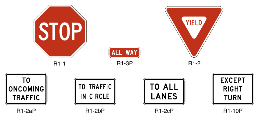
Signs shown: R1-1, R1-3P, R1-2, R1-2aP, R1-2bP, R1-2cP, R1-10P
SIGNING FOR RIGHT-OF-WAY AT INTERSECTIONS¶
§2B.06 General Considerations¶
Support
01. Unsignalized intersections represent the most common form of intersection right-of-way control. Selection of control type might be impacted by specific requirements of State law or local ordinances.
02. Roundabouts and traffic circles are circular intersection designs and are not traffic control devices. The decision to convert an intersection from a conventional intersection to a circular intersection is an engineering design decision and not a traffic control device decision. As such, criteria for conversion from a conventional intersection to a circular intersection are not included in the MUTCD.
Guidance
03. The type of traffic control used at an unsignalized intersection should be the least restrictive that provides appropriate levels of safety and efficiency for all road users.
Support
04. Some types of right-of-way control that can exist at an unsignalized intersection in order from the least restrictive to the most restrictive are the following:
- A. No intersection control (see Section 2B.09): There are no right-of-way traffic control devices on any of the approaches to the intersection.
- B. Yield control (see Section 2B.10): YIELD signs are placed on all approaches (for a circular intersection), on opposing approaches for a four-leg intersection, on a single approach for a three-leg intersection, or in the median of a divided highway. The YIELD signs are placed on the minor road.
- C. Minor road stop control (see Section 2B.11): STOP signs are typically placed on opposing approaches (for a four-leg intersection) or on a single approach (for a three-leg intersection). The STOP signs are normally placed on the minor road. Section 2B.07 contains guidance on selecting the minor road.
- D. All-way stop control (see Section 2B.12): STOP signs are placed on all approaches to the intersection.
Guidance
05. When selecting a form of intersection control, the following factors should be considered:
- A. Motor vehicle, bicycle, and pedestrian traffic volumes on all approaches; where the term units/day or units/hour is indicated, it should be the total of motor vehicle, bicycle, and pedestrian volume;
- B. Driver yielding behavior with regard to all modes of conflicting traffic, including bicyclists and pedestrians;
- C. Number and angle of approaches;
- D. Approach speeds;
- E. Sight distance available on each approach;
- F. Reported crash experience; and
- G. The presence of a grade crossing near the intersection.
Standard
06. YIELD or STOP signs shall not be used for speed control.
Support
07. Appropriate traffic calming or other speed control measures are available to control vehicle speeds, such as those that do not have the potential to diminish the effectiveness of traffic control devices when used for their specified purpose.
Standard
08. Because the potential for conflicting commands could create driver confusion, YIELD or STOP signs shall not be used in conjunction with any traffic control signal operation, except in the following cases:
- A. If the signal indication for an approach is a flashing red at all times;
- B. If a minor street or driveway is located within or adjacent to the area controlled by the traffic control signal, but does not require separate traffic signal control because an extremely low potential for conflict exists; or
- C. If a channelized turn lane is separated from the adjacent travel lanes by an island and the channelized turn lane is not controlled by a traffic control signal.
09. STOP signs and YIELD signs shall not be installed on different approaches to the same unsignalized intersection if those approaches conflict with or oppose each other, except as provided for in Items A and B in Paragraph 3 of Section 2B.10.
10. Portable or part-time STOP or YIELD signs shall not be used except for emergency and temporary traffic control zone purposes.
11. A portable or part-time (folding) STOP sign that is manually placed into view and manually removed from view shall not be used during a power outage to control a signalized approach unless the maintaining agency establishes that the signal indication that will first be displayed to that approach upon restoration of power is a flashing red signal indication and that the portable STOP sign will be manually removed from view prior to resuming stop-and-go operation of the traffic control signal.
Option
12. A portable or part-time (folding) STOP sign that is electrically or mechanically operated such that it only displays the stop message during a power outage and ceases to display the stop message upon restoration of power may be used during a power outage to control a signalized approach.
Support
13. The use of STOP signs at grade crossings is described in Sections 8B.04 and 8B.05.
14. Section 9B.01 contains provisions regarding the assignment of priority where a shared-use path crosses a roadway.
§2B.07 Determining the Minor Road for Unsignalized Intersections¶
Guidance
01. The selection of the minor road to be controlled by YIELD or STOP signs should be based on one or more of the following criteria:
- A. A roadway intersecting a designated through or numbered highway,
- B. A roadway with the lower functional classification,
- C. A roadway with the lower traffic volume,
- D. A roadway with the lower speed limit, and/or
- E. A roadway that intersects with a roadway that has a higher priority for one or more modes of travel.
02. When two roadways that have relatively equal volumes, speeds, and/or other characteristics intersect, the following factors should be considered in selecting the minor road for installation of YIELD or STOP signs:
- A. Controlling the direction that conflicts the most with established pedestrian crossing activity or school walking routes;
- B. Controlling the direction that has obscured vision, dips, or bumps that already require drivers to use lower operating speeds; and
- C. Controlling the direction that has the best sight distance from a controlled position to observe conflicting traffic.
§2B.08 Right-of-Way Intersection Control Considerations¶
Guidance
01. Before converting to a more restrictive form of right-of-way control at an unsignalized intersection, the following alternative treatments to address safety, operational, or other concerns should be among those to be considered:
- A. Where yield or stop controlled, installing Yield Ahead or Stop Ahead signs on the appropriate approaches to the intersection;
- B. Removing parking on one or more approaches;
- C. Removing sight distance obstructions;
- D. Installing signs along the major street to warn road users approaching the intersection;
- E. Relocating the stop line(s) and making other changes to improve the sight distance at the intersection;
- F. Installing measures designed to reduce speeds on the approaches;
- G. Installing an Intersection Control Beacon (see Section 4S.02) or Stop Beacon (see Section 4S.05) at the intersection to supplement STOP sign control;
- H. Installing a Warning Beacon (see Section 4S.03) on warning signs in advance of a stop-controlled intersection on major-street and/or minor-street approaches;
- I. Adding one or more lanes on a minor-street approach to reduce the number of vehicles per lane on the approach;
- J. Revising the geometrics at the intersection to channelize vehicular movements and reduce the time required for a vehicle to complete a movement, which could also assist pedestrians;
- K. Revising the geometrics at the intersection to add pedestrian median refuge islands and/or curb extensions;
- L. Installing roadway lighting if a disproportionate number of crashes occur at night;
- M. Restricting one or more turning movements on a full-time or part-time basis if alternate routes are available;
- N. Installing on the major street a pedestrian-actuated device: Warning Beacon (see Section 4S.03), rectangular rapid-flashing beacon (see Section 4L.01), or In-Roadway Warning Lights (see Chapter 4U), if pedestrian safety is the major concern;
- O. If the warrant is satisfied, installing all-way stop control;
- P. Installing a pedestrian hybrid beacon (see Chapter 4J) on the major street to address pedestrian safety;
- Q. Installing a circular intersection; and
- R. Employing other alternatives, depending on conditions at the intersection.
§2B.09 No Intersection Control¶
Guidance
01. The decision not to use intersection control should be based on engineering judgment.
Option
02. The following factors may be considered:
- A. Intersection sight distance is adequate on all approaches.
- B. All approaches to the intersection are a single lane and there are no separate turn lanes.
- C. The combined motor vehicle, bicycle, and pedestrian volume (existing or projected) entering the intersection from all approaches averages less than 1,000 units per day or 80 units in the peak hour.
- D. There are no marked crosswalks or bicycle lanes on any approach.
- E. None of the approaches to the intersection are for a through highway, main road, or higher functional classification.
- F. The angle of intersection is between 90 and 75 degrees.
- G. The functional classification of the intersecting streets is either the intersection of two local streets or the intersection of a local street with a collector street.
§2B.10 Yield Control¶
Guidance
01. At intersections where a full stop is not necessary at all times, consideration should first be given to using less restrictive measures such as YIELD signs.
02. Yield control should be considered when engineering judgment indicates that all of the following conditions exist:
- A. Intersection sight distance is adequate on the approaches to be controlled by YIELD signs.
- B. All approaches to the intersection are a single lane and there are no separate turn lanes.
- C. One of the following crash-related criteria applies:
- 1. For changing from no intersection control to yield control, there have been two or more reported crashes in the previous 12 months that are susceptible to correction by the installation of a YIELD sign.
- 2. For changing from minor road stop control to yield control, there have been two or fewer reported crashes in the previous 12 months.
- D. The combined motor vehicle, bicycle, and pedestrian volume entering the intersection averages less than 1,800 units per day or 140 units in the peak hour.
- E. The angle of intersection is between 90 and 75 degrees.
- F. The functional classification of the intersecting streets is either the intersection of two local streets or the intersection of a local street with a collector street.
Option
03. YIELD signs may be installed at an intersection when any of the following conditions apply:
- A. At the second intersection of a divided highway crossing or median break functioning as two separate intersections (see Figure 2B-19). In this case, a YIELD sign may be installed at the entrance to the second intersection.
- B. For a channelized turn lane that is separated from the adjacent travel lanes by an island, even if the adjacent lanes at the intersection are controlled by a highway traffic control signal or by a STOP sign.
- C. At an intersection where a special problem exists and where engineering judgment indicates the problem to be susceptible to correction by the use of the YIELD sign.
- D. Facing the entering roadway for a merge-type movement if engineering judgment indicates that control is needed because acceleration geometry and/or sight distance is not adequate for merging traffic operation.
- E. On low-volume rural roads if engineering judgment indicates that a YIELD sign would provide adequate control.
Guidance
04. The YIELD signs should be installed on opposing minor-street approaches (for a four-leg intersection) or on the minor-street approach (for a three-leg intersection). When two intersecting roadways have relatively equal volumes, speeds, and other characteristics, yield control should be installed on the approach that conflicts the most with established pedestrian crossing activity, school walking routes, or bicycle crossing activity.
Standard
05. A YIELD sign shall be used to require road users to yield the right-of-way to other traffic at the entrance to a roundabout. YIELD signs at roundabouts shall be used to control the approach roadways and shall not be used to control the circulatory roadway.
06. YIELD signs shall not be placed on all of the approaches to an intersection, except at roundabouts.
§2B.11 Minor Road Stop Control¶
Guidance
01. Stop control on the minor-road approach or approaches to an intersection should be considered when engineering judgment indicates that one or more of the following conditions exist:
- A. A restricted view exists that requires road users to stop in order to adequately observe conflicting traffic on the through street or highway.
- B. Crash records indicate that:
- 1. For a four-leg intersection, there are three or more reported crashes in a 12-month period or six or more reported crashes in a 36-month period. The crashes should be susceptible to correction by installation of minor-road stop control.
- 2. For a three-leg intersection, there are three or more reported crashes in a 12-month period or five or more reported crashes in a 36-month period. The crashes should be susceptible to correction by installation of minor-road stop control.
- C. The intersection is of a lower functional classification road with a higher functional classification road.
- D. Conditions that previously supported the installation of all-way stop control no longer exist.
02. On low-volume rural roads, a STOP sign should be considered at an intersection where engineering judgment indicates that Item C in Paragraph 1 of this Section is applicable or where the intersection has inadequate sight distance for the operating vehicle speeds.
§2B.12 All-Way Stop Control¶
Support
01. The provisions in the following sections describe warrants for the recommended engineering study to determine all-way stop control. Warrants are not a substitute for engineering judgment. The fact that a warrant for a particular traffic control device is met is not conclusive justification to install or not install all-way stop control. Because each intersection will have unique characteristics that affect its operational performance or safety, it is the engineering study for a given intersection that is ultimately the basis for a decision to install or not install all-way stop control.
02. All-way stop controls at intersections with substantially differing approach volumes can reduce the effectiveness of these devices for all roadway users.
Guidance
03. The decision to establish all-way stop control at an unsignalized intersection should be based on an engineering study. The engineering study for all-way stop control should include an analysis of factors related to the existing operation and safety at the intersection, the potential to improve these conditions, and the applicable factors contained in the following all-way stop control warrants:
- A. All-Way Stop Control Warrant A: Crash Experience (see Section 2B.13)
- B. All-Way Stop Control Warrant B: Sight Distance (see Section 2B.14)
- C. All-Way Stop Control Warrant C: Transition to Signal Control or Transition to Yield Control at a Circular Intersection (see Section 2B.15)
- D. All-Way Stop Control Warrant D: 8-Hour Volume (Vehicles, Pedestrians, Bicycles) (see Section 2B.16)
- E. All-Way Stop Control Warrant E: Other Factors (see Section 2B.17)
Option
04. The decision to install all-way stop control on site roadways open to public travel may be based on engineering judgment.
Standard
05. The satisfaction of an all-way stop control warrant or warrants shall not in itself require the installation of all-way stop control at an unsignalized intersection.
§2B.13 All-Way Stop Control Warrant A: Crash Experience¶
Option
All-way stop control may be installed at an intersection where an engineering study indicates that:
- A. For a four-leg intersection, there are five or more reported crashes in a 12-month period or six or more reported crashes in a 36-month period that were of a type susceptible to correction by the installation of all-way stop control.
- B. For a three-leg intersection, there are four or more reported crashes in a 12-month period or five or more reported crashes in a 36-month period that were of a type susceptible to correction by the installation of all-way stop control.
§2B.14 All-Way Stop Control Warrant B: Sight Distance¶
Option
01. All-way stop control may be installed at an intersection where an engineering study indicates that sight distance on the minor-road approaches controlled by a STOP sign is not adequate for a vehicle to turn onto or cross the major (uncontrolled) road.
Support
02. At such a location, a road user, after stopping, cannot see conflicting traffic and is not able to negotiate the intersection unless conflicting cross traffic is also required to stop.
§2B.15 All-Way Stop Control Warrant C: Transition to Signal Control or Transition to Yield Control at a Circular Intersection¶
Option
01. All-way stop control may be installed at locations where all-way stop control is an interim measure that can be installed to control traffic while arrangements are being made for the installation of a traffic control signal (see Chapter 4C) at the intersection or for the installation of yield control at a circular intersection.
§2B.16 All-Way Stop Control Warrant D: 8-Hour Volume (Vehicles, Pedestrians, Bicycles)¶
Option
01. All-way stop control may be installed at an intersection where an engineering study indicates:
- A. The combined motor vehicle, bicycle, and pedestrian volume entering the intersection from the major-street approaches is at least 300 units per hour for each of any 8 hours of a typical day; and
- B. The combined motor vehicle, bicycle, and pedestrian volume entering the intersection from the minor-street approaches is at least 200 units per hour for each of any of the same 8 hours.
02. If the 85th-percentile approach speed of the major-street traffic exceeds 40 mph, the minimum vehicular volume warrants may be reduced to 70 percent of the values given in Items A and B in Paragraph 1 of this Section.
§2B.17 All-Way Stop Control Warrant E: Other Factors¶
Option
01. All-way stop control may be installed at an intersection where an engineering study indicates that all-way stop control is needed due to other factors not addressed in the other all-way stop control warrants. Such other factors may include, but are not limited to, the following:
- A. The need to control left-turn conflicts,
- B. An intersection of two residential neighborhood collector (through) streets of similar design and operating characteristics where all-way stop control would improve traffic operational characteristics of the intersection, or
- C. Where pedestrian and/or bicyclist movements support the installation of all-way stop control.
§2B.18 STOP Sign or YIELD Sign Placement¶
Standard
01. The STOP or YIELD sign shall be installed on the near side of the intersection on the right-hand side of the approach to which it applies. When the STOP or YIELD sign is installed at this required location and the sign visibility is restricted, a Stop Ahead sign (see Section 2C.35) shall be installed in advance of the STOP sign or a Yield Ahead sign (see Section 2C.35) shall be installed in advance of the YIELD sign.
02. The STOP or YIELD sign shall be located as close as practicable to the intersection it regulates, while optimizing its visibility to the road user it is intended to regulate.
03. STOP signs and YIELD signs shall not be mounted on the same post.
Support
04. Section 2A.05 contains information about mounting signs back-to-back with a STOP or YIELD sign.
Guidance
05. STOP or YIELD signs should not be placed farther than 50 feet from the edge of the pavement of the intersected roadway (see Drawing F in Figure 2A-3).
06. Supplemental plaques used in conjunction with a STOP or YIELD sign should be limited to those specified for such use in this Manual.
Option
07. Where drivers proceeding straight ahead must yield to traffic approaching from the opposite direction, such as at a one-lane bridge, a TO ONCOMING TRAFFIC (R1-2aP) plaque (see Figure 2B-1) may be mounted below the YIELD sign.
08. Where drivers must yield to traffic in a multi-lane roundabout, a TO TRAFFIC IN CIRCLE (R1-2bP) or TO ALL LANES (R1-2cP) plaque (see Figure 2B-1) may be mounted below the YIELD sign.
Support
09. Figure 2A-3 shows examples of some typical placements of STOP signs and YIELD signs.
10. Section 2A.13 contains additional information about separate and combined mounting of other signs with STOP or YIELD signs.
Guidance
11. Stop lines that are used to supplement a STOP sign should be located as described in Section 3B.19. Yield lines that are used to supplement a YIELD sign should be located as described in Section 3B.19.
12. Where there is a marked crosswalk at the intersection, the STOP sign should be installed in advance of the edge of the crosswalk that is nearest to the approaching traffic.
13. Except at roundabouts and channelized right-turn lanes, where there is a marked crosswalk at the intersection, the YIELD sign should be installed in advance of the edge of the crosswalk that is nearest to the approaching traffic.
14. Where two roads intersect at an acute angle, the STOP or YIELD sign should be positioned at an angle, or shielded, so that the legend is out of view of traffic to which it does not apply.
15. If a raised splitter island is available on the left-hand side of a multi-lane roundabout approach, an additional YIELD sign should be placed on the left-hand side of the approach.
Option
16. If a raised splitter island is available on the left-hand side of a single-lane roundabout approach, an additional YIELD sign may be placed on the left-hand side of the approach.
17. At wide-throat intersections or where two or more approach lanes of traffic exist on the signed approach, an additional STOP or YIELD sign may be installed on the left-hand side of the road and/or a stop or yield line may be used to improve observance of the right-of-way control. At channelized intersections or at divided roadways separated by a median or divisional island, the additional STOP or YIELD sign may be placed on a channelizing island, or in the median or on the divisional island. An additional STOP or YIELD sign may also be placed overhead facing the approach at the intersection to improve observance of the right-of-way control.
Standard
18. More than one STOP sign or more than one YIELD sign shall not be placed on the same support facing in the same direction.
Option
19. For a yield-controlled channelized right-turn movement onto a roadway without an acceleration lane and for an entrance ramp onto a freeway or expressway without an acceleration lane, a NO MERGE AREA (W4-5aP) supplemental plaque (see Section 2C.45) may be mounted below a Yield Ahead (W3-2) sign and/or below a YIELD (R1-2) sign when engineering judgment indicates that road users would expect an acceleration lane to be present.
§2B.19 Yield Here To Pedestrians Signs and Stop Here For Pedestrians Signs (R1-5 Series)¶
Support
01. The R1-5 series signs are intended to mitigate the scenario that can place pedestrians at risk by blocking other drivers’ view of pedestrians and by blocking the pedestrians’ view of the vehicles approaching in the adjacent lanes.
Standard
02. Yield Here to (Stop Here for) Pedestrians (R1-5, R1-5a, R1-5b, R1-5c, R1-5d, and R1-5e) signs (see Figure 2B-2) shall be used if yield (stop) lines are used in advance of a marked crosswalk only where it crosses an uncontrolled multi-lane approach. The Stop Here for Pedestrians signs shall only be used where the law specifically requires that a driver must stop for a pedestrian in a crosswalk. The legend STATE LAW shall not be displayed on the R1-5 series signs.
Guidance
03. If yield (stop) lines and Yield Here to (Stop Here for) Pedestrians signs are used in advance of a crosswalk that crosses an uncontrolled multi-lane approach, the signs should be placed 20 to 50 feet in advance of the nearest edge of the crosswalk (see Section 3B.19 and Figure 3B-16).
Standard
04. When used with a School Crossing assembly within school zones (see Part 7), the R1-5a and R1-5c signs shall be used in place of the R1-5 and R1-5b signs in accordance with Paragraph 2 of this Section.
05. When used with a Trail Crossing assembly (see Section 2C.54), the R1-5d and R1-5e signs shall be used in place of the R1-5 and R1-5b signs in accordance with Paragraph 2 of this Section.
Guidance
06. When Yield Here to (Stop Here for) Pedestrians signs are provided in advance of a crosswalk across an multi-lane approach, parking should be prohibited in the area between the yield (stop) line and the crosswalk.
07. Yield (stop) lines and Yield Here to (Stop Here for) Pedestrians signs should not be used in advance of crosswalks that cross an approach to or departure from a roundabout.
Option
08. Yield Here to (Stop Here for) Pedestrians signs may be used in accordance with Paragraphs 2 through 4 of this Section even if yield (stop) lines are not used.
09. A Pedestrian Crossing (W11-2) warning sign may be placed overhead or may be post-mounted with a diagonal downward-pointing arrow (W16-7P) plaque at the crosswalk location where Yield Here to (Stop Here for) Pedestrians signs have been installed in advance of the crosswalk.
Standard
10. If a W11-2 sign is post-mounted at the crosswalk location where a Yield Here to (Stop Here for) Pedestrians sign is used on the approach, the Yield Here to (Stop Here for) Pedestrians sign shall not be placed on the same post as the W11-2 sign.
Option
11. An advance Pedestrian Crossing (W11-2) warning sign with an AHEAD or a distance supplemental plaque may be used in conjunction with a Yield Here to (Stop Here for) Pedestrians sign on the approach to the same crosswalk.
12. In-Street Pedestrian Crossing signs and Yield Here to (Stop Here for) Pedestrians signs may be used together at the same crosswalk.
§2B.20 In-Street and Overhead Pedestrian and Trail Crossing Signs (R1-6 and R1-9 Series)¶
Option
01. The In-Street Pedestrian Crossing (R1-6 or R1-6a) sign (see Figure 2B-2), In-Street Trail Crossing (R1-6d or R1-6e) sign (see Figure 2B-2), the Overhead Pedestrian Crossing (R1-9 or R1-9a) sign (see Figure 2B-2), or the Overhead Trail Crossing (R1-9d or R1-9e) sign (see Figure 2B-2) may be used to remind road users of laws regarding right-of-way at an unsignalized crosswalk. The legend STATE LAW may be displayed at the top of the R1-6 series and R1-9 series signs if applicable. On the R1-6 series signs, the legends STOP or YIELD may be used instead of the appropriate STOP sign or YIELD sign symbol.
02. Highway agencies may develop and apply criteria for determining the applicability of In-Street Pedestrian Crossing signs.
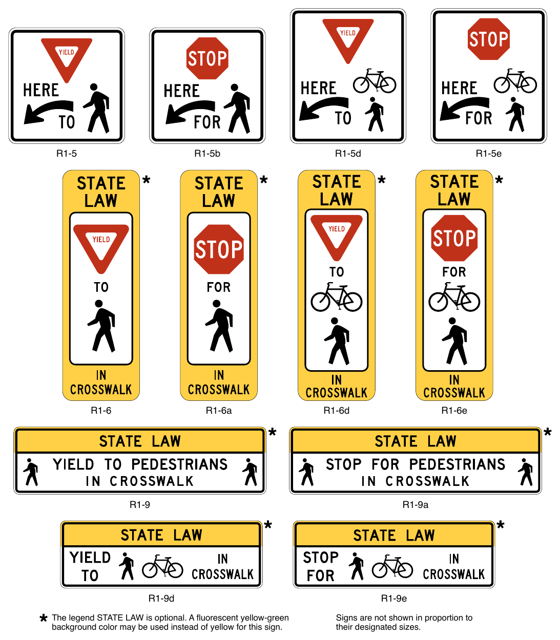
Signs shown: R1-5, R1-5b, R1-5d, R1-5e, R1-6, R1-6a, R1-6d, R1-6e, R1-9, R1-9a, R1-9d, R1-9e
The legend STATE LAW is optional. A fluorescent yellow-green background color may be used instead of yellow for this sign. R1-5d R1-5e R1-6d R1-6e R1-9a R1-9e Signs are not shown in proportion to their designated sizes.
Standard
03. The STOP FOR legend shall only be used in States where the State law specifically requires that a driver must stop for a pedestrian or a bicyclist in a crosswalk.
04. If used, In-Street Pedestrian or Trail Crossing signs shall only be placed in the roadway at the crosswalk location on the center line, on a median island, on a lane line, or on an edge line.
05. The In-Street Pedestrian or Trail Crossing sign shall not be post-mounted on the left-hand or right-hand side of the roadway.
Support
06. Section 3I.02 contains information about the use of tubular markers to provide additional emphasis for a pedestrian crossing.
Standard
07. If used, the Overhead Pedestrian or Trail Crossing sign shall be placed over the roadway at the crosswalk location.
08. When used at an uncontrolled crossing, the In-Street or Overhead Pedestrian Crossing sign shall be used only as a supplement to a Pedestrian Crossing (W11-2) warning sign with a diagonal downward-pointing arrow (W16-7P) plaque at the crosswalk location.
09. When used at an uncontrolled crossing, the In-Street or Overhead Trail Crossing sign shall be used only as a supplement to a Trail Crossing (W11-15) warning sign with a diagonal downward-pointing arrow (W16-7P) plaque at the crosswalk location.
10. An In-Street or Overhead Pedestrian or Trail Crossing sign shall not be placed in advance of the crosswalk to educate road users about the State law prior to reaching the crosswalk, nor shall it be installed as an educational display that is not near any crosswalk.
Guidance
11. If an island (see Chapter 3J) is available, the In-Street Pedestrian or Trail Crossing sign, if used, should be placed on the island.
Option
12. In-Street Pedestrian or Trail Crossing signs may be mounted back-to-back in the median or on the center line of an undivided roadway.
Standard
13. The In-Street Pedestrian or Trail Crossing sign and the Overhead Pedestrian Crossing or Trail sign shall not be used at crosswalks on approaches controlled by a traffic control signal, pedestrian hybrid beacon, or an emergency-vehicle hybrid beacon.
14. Except where the In-Street Crossing sign is placed on a physical island, the sign support shall be designed to bend over and then bounce back to its normal vertical position when struck by a vehicle.
Option
15. The In-Street and Overhead Pedestrian and Trail Crossing sign may be used at intersections or midblock pedestrian crossings with flashing beacons.
Support
16. The provisions of Section 2A.15 concerning mounting height are not applicable for the In-Street Pedestrian Crossing sign. Section 2A.18 contains information about sign mounting methods.
Standard
17. The top of an In-Street Pedestrian or Trail Crossing sign shall be a maximum of 4 feet above the pavement surface. The top of an In-Street Pedestrian or Trail Crossing sign placed in an island shall be a maximum of 4 feet above the island surface.
Option
18. The In-Street Pedestrian Crossing or Trail Crossing signs may be used seasonally to prevent damage in winter because of plowing operations, and may be removed at night if the pedestrian activity at night is minimal.
19. Both sign mounting types, In-Street Crossing (R1-6 series) signs and Overhead Crossing (R1-9 series) signs, may be used together at the same crosswalk.
SPEED LIMIT SIGNS AND PLAQUES¶
§2B.21 Speed Limit Sign (R2-1)¶
Support
01. In general, the maximum speed limits applicable to rural and urban roads are established:
- A. Statutorily – a maximum speed limit applicable to a particular class of road, such as freeways or city streets, that is established by State law; or
- B. As speed zones – based on engineering studies.
02. State statutory limits might restrict the maximum speed limit that can be established on a particular road, notwithstanding what an engineering study might indicate.
03. Agencies with designated authorities to set speed limits, which include States, and sometimes local jurisdictions, can establish non-statutory speed limits or designate reduced speed zones using an engineering study. Setting appropriate speed limits is especially important to ensure safety for all road users in varying types of contexts, particularly on roadways where adjacent land use suggests that trips could be served by varied modes. These situations include urban and suburban non-freeway arterials or rural arterials that serve as main streets in smaller communities, consistent with the context classifications of urban core, urban, suburban, and rural towns found in “A Policy on Geometric Design of Highways and Streets,” 2018 Edition, AASHTO. When setting a speed limit, a range of factors such as land-use context, pedestrian and bicyclist activity, crash history, intersection spacing, driveway density, roadway geometry, roadside conditions, roadway functional classification, traffic volume, and observed speeds can influence the speed limit determined in the engineering study. The engineering study will determine which of the recommended factors will prevail in setting the speed limit.
04. Jurisdictions can use speed limit setting tools and methods such as expert systems and those consistent with the safe system approach as part of the required engineering study for a non-statutory speed limit. As speed limit setting tools vary, jurisdictions need to be aware of their limitations and advantages, possible variation between the tools and the need to explore gaps or weaknesses of tools, and weigh the output accordingly in consideration of setting speed limits.
05. To achieve desired operating speeds, agencies often implement other speed management strategies concurrently with setting speed limits, such as traffic calming measures, geometric design features, speed safety cameras, and increased enforcement.
Standard
06. Speed zones (other than statutory speed limits) shall only be established on the basis of an engineering study that has been performed in accordance with traffic engineering practices. The engineering study shall consider the roadway context.
Guidance
07. Among the factors that should be considered when conducting an engineering study for establishing or reevaluating speed limits within speed zones are the following:
- A. Roadway environment (such as roadside development, number and frequency of driveways and access points, and land use), functional classification, public transit volume and location or frequency of stops, parking practices, and pedestrian and bicycle facilities and activity;
- B. Roadway characteristics (such as lane widths, shoulder condition, grade, alignment, median type, and sight distance);
- C. Geographic context (such as an urban district, rural town center, non-urbanized rural area, or suburban area), and multi-modal trip generation;
- D. Reported crash experience for at least a 12-month period;
- E. Speed distribution of free-flowing vehicles including the pace, median (50th-percentile), and 85th-percentile speeds; and
- F. A review of past speed studies to identify any trends in operating speeds.
08. When the 85th-percentile speed is appreciably greater than the posted speed limit, and the roadway context does not support setting a higher speed limit, the engineering study should consider whether changes to geometric features, enforcement, and/or other speed-reduction countermeasures might improve compliance with the posted speed limit. A similar approach should be used if the results of past speed studies indicate that the 85th-percentile speed has consistently increased.
09. On urban and suburban arterials, and on rural arterials that serve as main streets through developed areas of communities, the 85th-percentile speed should not be used to set speed limits without consideration of all factors described in Paragraph 7 of this Section.
10. On a freeway, expressway, or rural highway (outside urbanized locations or conditions), the speed limit that is posted within a speed zone should be within 5 mph of the 85th-percentile speed of free-flowing motor-vehicle traffic under the following conditions:
- A. All factors described in Paragraph 7 of this Section have been considered and determined to be nonmitigating, and
- B. The measures described in Paragraph 8 of this Section have been considered to the extent practicable.
11. State and local agencies should conduct engineering studies to reevaluate non-statutory speed limits on segments of their roadways that have undergone significant changes since the last review (such as changes to roadway context, the addition or elimination of parking or driveways, changes in the number of travel lanes, changes in the configuration of bicycle lanes, changes to road geometrics, changes in traffic control signal coordination, or significant changes in traffic volumes).
12. Speed studies for signalized intersection approaches should be taken outside the influence area of the traffic control signal, which is generally considered to be approximately 1/2 mile, to avoid obtaining skewed results for the speed distribution. If the signal spacing is less than 1 mile, the speed study should be at approximately the middle of the segment.
Standard
13. The Speed Limit (R2-1) sign (see Figure 2B-3) shall display the limit established by law, ordinance, regulation, or as adopted by the authorized agency based on an engineering study. The speed limits displayed shall be in multiples of 5 mph.
14. Speed Limit (R2-1) signs, indicating speed limits for which posting is required by law, shall be located at the points of change from one speed limit to another.
15. At the downstream end of the section to which a particular speed limit applies, a Speed Limit sign showing the next speed limit shall be installed.
16. Speed Limit signs indicating the statutory speed limits shall be installed at entrances to the State and, where appropriate, at jurisdictional boundaries in urban areas.
Guidance
17. Additional Speed Limit signs should be installed beyond interchanges and major intersections and at other locations where it is necessary to remind road users of the speed limit that is applicable.
Support
18. The 2nd Edition of the “Traffic Control Devices Handbook,” 2013, Institute of Transportation Engineers” contains suggested criteria on the spacing of speed limit signs.
Option
19. If a jurisdiction has a policy of installing Speed Limit signs in accordance with statutory requirements only on the streets that enter a city, neighborhood, or residential area to indicate the speed limit that is applicable to the entire city, neighborhood, or residential area unless otherwise posted, a CITYWIDE (R2-5aP), NEIGHBORHOOD (R2-5bP), or RESIDENTIAL (R2-5cP) plaque may be mounted above the Speed Limit sign and an UNLESS OTHERWISE POSTED (R2-5P) plaque may be mounted below the Speed Limit sign (see Figure 2B-3).
Support
20. Section 2C.40 contains information about the use of speed zone signs to inform road users of a reduced or variable speed zone to provide advance notice to comply with the posted speed limit ahead.
Option
21. If a W3-5b sign is posted to provide notice of a variable speed zone, an END VARIABLE SPEED LIMIT (R2-13) sign (see Figure 2B-3) may be installed at the downstream end of the zone to provide notice to road users of the termination of the speed zone.
Standard
22. If a W3-5c sign is posted to provide notice of a truck speed zone, an END TRUCK SPEED LIMIT (R2-14) sign (see Figure 2B-3) shall be installed at the downstream end of the zone to provide notice to road users of the termination of the speed zone.
Guidance
23. An advisory speed plaque (see Section 2C.59) mounted below a warning sign should be used to warn road users of an advisory speed for a roadway condition. A Speed Limit sign should not be used for this purpose.
24. Advance traffic control warning signs (see Section 2C.35), intersection warning signs (see Section 2C.41), and/or other traffic control devices are appropriate warning prior to a signalized intersection. A Speed Limit sign should not be used for this purpose.
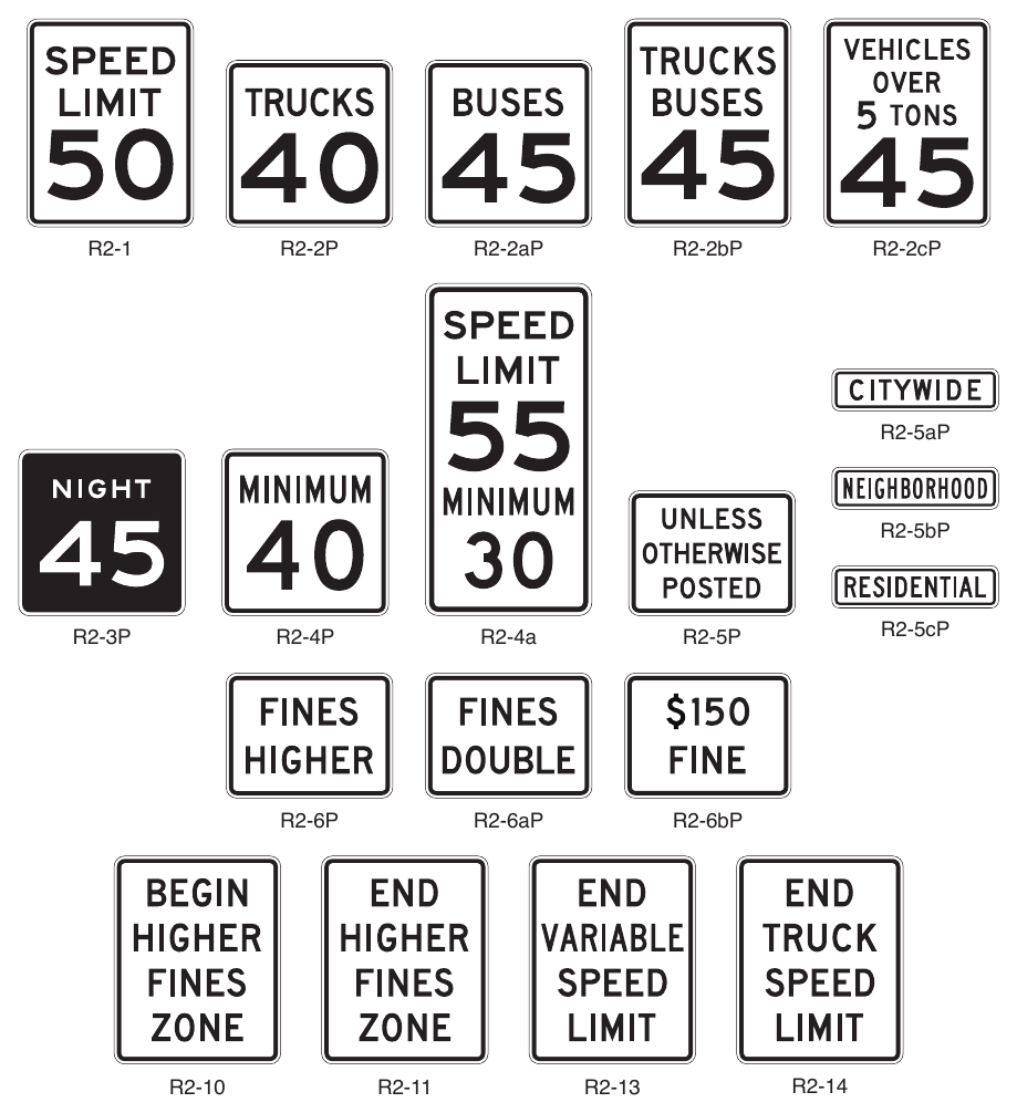
Signs shown: R2-1, R2-2P, R2-2aP, R2-2bP, R2-2cP, R2-5aP, R2-5bP, R2-5cP, R2-3P, R2-4P, R2-4a, R2-5P, R2-6P, R2-6aP, R2-6bP, R2-10, R2-11, R2-13, R2-14
Option
25. Two types of Speed Limit signs may be used: one to designate passenger car speeds, including any nighttime information or maximum or minimum speed limit that might apply; and the other to show any special speed limits for trucks and other vehicles.
Guidance
26. No more than three speed limits should be displayed on any one Speed Limit sign or assembly.
Option
27. A variable speed limit sign that changes the speed limit for traffic and ambient conditions may be installed provided that the appropriate speed limit is displayed at the proper times and locations in accordance with Paragraphs 9 and 10 of this Section.
Standard
28. The variable speed limit sign legend “SPEED LIMIT” shall be a black legend on a white retroreflective background. The variable speed limit legend shall be displayed in white LEDs on an opaque black background.
Support
29. Section 2C.13 contains information about the use of a Vehicle Speed Feedback plaque mounted below a Speed Limit sign that displays to approaching drivers the speed at which they are traveling.
30. Advisory speed signs and plaques are discussed in Sections 2C.12 and 2C.59. Temporary traffic control zone speed signs are discussed in Part 6. The WORK ZONE (G20-5aP) plaque intended for installation above a Speed Limit sign is discussed in Section 6G.08. School Speed Limit signs are discussed in Section 7B.05.
§2B.22 Vehicle Speed Limit Plaques (R2-2P Series)¶
Standard
01. Where a special speed limit applies to certain classes of vehicles, the Truck Speed Limit (R2-2P) plaque, Bus Speed Limit (R2-2aP) plaque, Truck-Bus Speed Limit (R2-2bP) plaque, or Vehicles over X Tons Speed Limit (R2-2cP) plaque (see Figure 2B-3) shall be displayed below the Speed Limit (R2-1) sign, except as provided in Paragraph 2 of this Section.
Option
02. The legend of a Vehicle Speed Limit (R2-2P series) plaque may be combined in a single sign and displayed below the SPEED LIMIT XX legend, similar to the Combined Maximum and Minimum Speed Limits (R2-4a) sign (see Section 2B.24).
03. A different vehicle class legend may be substituted on the R2-2P series plaque for other classes of vehicles not included in Paragraph 1 of this Section.
§2B.23 Night Speed Limit Plaque (R2-3P)¶
Standard
01. Where different speed limits are prescribed for day and night, both limits shall be posted.
Guidance
02. A Night Speed Limit (R2-3P) plaque (see Figure 2B-3) should be reversed using a white retroreflective legend and border on a black background.
Option
03. A Night Speed Limit plaque may be combined with or installed below the standard Speed Limit (R2-1) sign.
§2B.24 Minimum Speed Limit Plaque (R2-4P) and Combined Maximum and Minimum Speed Limits Sign (R2-4a)¶
Standard
01. A Minimum Speed Limit (R2-4P) plaque (see Figure 2B-3) shall be displayed only in combination with a Speed Limit sign. Where used, the R2-4P plaque shall be mounted below a Speed Limit (R2-1) sign.
Option
02. Where engineering judgment determines that slow speeds on a highway might impede the normal and reasonable movement of traffic, the Minimum Speed Limit (R2-4P) plaque may be installed below a Speed Limit (R2-1) sign to indicate the minimum legal speed. In lieu of a sign assembly with the R2-1 sign and R2-4P plaque, the Combined Maximum and Minimum Speed Limits (R2-4a) sign may be used.
§2B.25 Higher Fines Signs and Plaque (R2-6P, R2-10, and R2-11)¶
Standard
01. Except as provided in Paragraph 3 of this Section, if increased fines are imposed for traffic violations within a designated zone of a roadway, a BEGIN HIGHER FINES ZONE (R2-10) sign (see Figure 2B-3) or a FINES HIGHER (R2-6P) plaque (see Figure 2B-3) shall be used to provide notice to road users.
02. If an R2-10 sign or an R2-6P plaque is posted to provide notice of increased fines for traffic violations, an END HIGHER FINES ZONE (R2-11) sign (see Figure 2B-3) shall be installed at the downstream end of the zone to provide notice to road users of the termination of the increased fines zone.
Option
03. The BEGIN HIGHER FINES ZONE (R2-10) sign or FINES HIGHER (R2-6P) plaque may be omitted where the higher fines zone is established by statute.
Guidance
04. The BEGIN HIGHER FINES ZONE sign or FINES HIGHER plaque should be located at the beginning of the temporary traffic control zone, school zone, or other applicable designated zone and just beyond any interchanges, major intersections, or other major traffic generators.
05. Agencies should limit the use of the Higher Fines signs and plaque to locations where work is actually underway, or to locations where the roadway, shoulder, or other conditions, including the presence of a school zone and/or a reduced school speed limit zone, require a speed reduction or extra caution on the part of the road user.
Standard
06. The Higher Fines signs and plaque shall have a black legend and border on a white rectangular background. All supplemental plaques mounted below the Higher Fines signs and plaque shall have a black legend and border on a white rectangular background.
07. The FINES HIGHER plaque shall be mounted below an applicable regulatory or warning sign in a temporary traffic control zone (see Section 6G.08), a school zone (see Section 7B.06), or other applicable designated zone.
Option
08. Alternate legends such as BEGIN (or END) DOUBLE FINES ZONE may also be used for the R2-10 and R2-11 signs.
09. The legend FINES HIGHER on the R2-6P plaque may be replaced by FINES DOUBLE (R2-6aP), $XX FINE (R2-6bP), or another legend appropriate to the specific regulation (see Figure 2B-3).
10. The following may be mounted below an R2-10 sign or R2-6P plaque:
- A. A supplemental plaque specifying the times that the higher fines are in effect (similar to the S4-1P plaque shown in Figure 7B-1),
- B. A supplemental plaque WHEN CHILDREN (WORKERS) ARE PRESENT, or
- C. A supplemental plaque WHEN FLASHING (similar to the S4-4P plaque shown in Figure 7B-1) if used in conjunction with a Speed Limit Sign Beacon (see Section 4S.04).
MOVEMENT AND LANE CONTROL SIGNS AND PLAQUES¶
§2B.26 Movement Prohibition Signs (R3-1 through R3-4, R3-18, and R3-27)¶
Standard
01. Movement Prohibition signs (see Figure 2B-4) shall be installed where specific movements are prohibited at an intersection approach except as provided in Paragraphs 13 and 17 of this Section.
Guidance
02. Movement Prohibition signs should only be used to prohibit a turn or through movement from an entire approach and should not be used to designate movements that are required or permitted from a specific lane or lanes on a multi-lane approach.
03. Movement Prohibition signs should be placed where they will be most easily seen by road users who might be intending to make the movement.
04. If a No Right Turn (R3-1) sign (see Figure 2B-4) is used, at least one should be placed either over the roadway or at a right-hand corner of the intersection.
05. If a No Left Turn (R3-2) sign (see Figure 2B-4) is used, at least one should be placed over the roadway, at the far left corner of the intersection, on a median, or in conjunction with the STOP sign or YIELD sign located on the near right corner.
06. Except as provided in Item C in Paragraph 11 of this Section for signalized locations, if a NO TURNS (R3-3) sign (see Figure 2B-4) is used, two signs should be used, one at a location specified for a No Right Turn sign and one at a location specified for a No Left Turn sign.
07. If a No U-Turn (R3-4) sign (see Figure 2B-4) or a combination No U or Left Turn (R3-18) sign (see Figure 2B-4) is used, at least one should be used at a location specified for a No Left Turn sign.
08. If both left turns and U-turns are prohibited, the combination No U or Left Turn (R3-18) sign should be used instead of separate R3-2 and R3-4 signs.
Support
09. Sections 2B.27 through 2B.30 contain information regarding lane control signs that indicate the required or permitted movements from individual lanes.
Guidance
10. If a No Straight Through (R3-27) sign (see Figure 2B-4) is used, at least one should be placed either over the roadway or at a location where it can be seen by road users who might be intending to travel straight through the intersection.
11. If turn prohibition signs are installed in conjunction with traffic control signals:
- A. The No Right Turn sign should be installed adjacent to a signal face viewed by road users in the right-hand lane.
- B. The No Left Turn (or No U-Turn or combination No U or Left Turn) sign should be installed adjacent to a signal face viewed by road users in the left-hand lane.
- C. A NO TURNS sign should be placed adjacent to a signal face viewed by all road users on that approach, or two signs should be used.
Option
12. If turn prohibition signs are installed in conjunction with traffic control signals, an additional turn prohibition sign may be post-mounted to supplement the sign mounted overhead.
13. Where ONE WAY signs are used (see Section 2B.49), No Left Turn and No Right Turn signs may be omitted.
14. Where the movement restriction applies to certain vehicle classes, signs incorporating a supplementary legend, modified as appropriate, may be used to indicate the specific vehicle class restriction (R3-1b through R3-1d) or exception (R3-1e and R3-1f) (see Figure 2B-4). When the movement restriction applies during certain time periods only, the following Movement Prohibition signing alternatives may be used and are listed in order of preference:
- A. A blank-out or changeable message sign (see Chapter 2L) that displays the prohibited movement only during the time that the movement prohibition is applicable, especially at signalized intersections.
- B. Permanently-mounted signs incorporating a supplementary legend showing the hours and days during which the prohibition is applicable (R3-1g and R3-1h) (see Figure 2B-4).
- C. Portable signs, installed by proper authority, located off the roadway at each corner of the intersection. The portable signs are only to be used during the time that the movement prohibition is applicable.
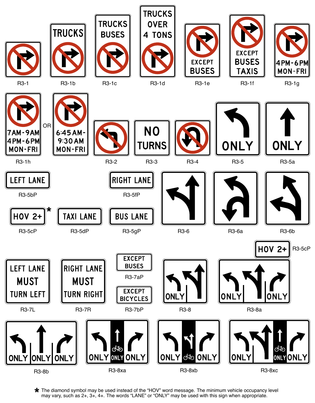
Signs shown: R3-1, R3-1b, R3-1c, R3-1d, R3-1e, R3-1f, R3-1g, R3-1h, R3-2, R3-3, R3-4, R3-5, R3-5a, R3-5bP, R3-5fP, R3-5cP, R3-5dP, R3-5gP, R3-6, R3-6a, R3-6b, R3-7aP, R3-7L, R3-7R, R3-7bP, R3-8, R3-8a, R3-8b
The diamond symbol may be used instead of the “HOV” word message. The minimum vehicle occupancy level may vary, such as 2+, 3+, 4+. The words “LANE” or “ONLY” may be used with this sign when appropriate.
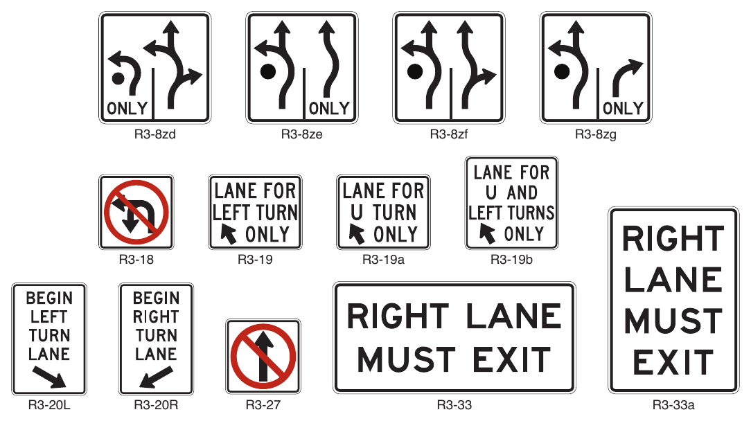
Signs shown: R3-18, R3-19, R3-19a, R3-19b, R3-20L, R3-20R, R3-27, R3-33, R3-33a, R3-2, R3-4
and Plaques (Sheet 2 of 2) R3-8zd R3-8ze R3-8zf R3-8zg R3-19a R3-19b R3-33a
Standard
15. The blank-out part-time electronic-display Movement Prohibition sign shall consist of a red circle and diagonal with a white prohibited movement on an opaque black background.
Option
16. Movement Prohibition signs may be omitted at a ramp entrance to an expressway or a channelized intersection where the design is such as to indicate clearly the one-way traffic movement on the ramp or turning lane.
Standard
17. The No Left Turn (R3-2) sign, the No U-Turn (R3-4) sign, and the combination No U or Left Turn (R3-18) sign shall not be used at approaches to roundabouts to prohibit drivers from turning left onto the circulatory roadway of a roundabout.
Support
18. At roundabouts, the use of R3-2, R3-4, or R3-18 signs to prohibit left turns onto the circulatory roadway might confuse drivers about the possible legal turning movements around the roundabout. Roundabout Circulation (R6-5P) plaques (see Section 2B.51) and/or ONE WAY (R6-1 or R6-2) signs are appropriate to indicate the travel direction within a roundabout.
§2B.27 Intersection Lane Control Signs (R3-5 through R3-8)¶
Standard
01. Intersection Lane Control signs (see Figure 2B-4), if used, shall require road users in certain lanes to turn, shall permit turns from a lane where such turns would otherwise not be permitted, shall require a road user to stay in the same lane and proceed straight through an intersection, or shall indicate permitted movements from a lane.
Support
02. Intersection Lane Control signs have three applications:
- A. Mandatory Movement Lane Control (R3-5 series and R3-7 series) signs,
- B. Optional Movement Lane Control (R3-6 series) signs, and
- C. Advance Intersection Lane Control (R3-8 series) signs.
Guidance
03. When Intersection Lane Control signs are mounted overhead, each sign used should be placed over the lane or a projection of the lane to which it applies.
04. On signalized approaches where through lanes that become mandatory turn lanes, multiple-lane turns that include shared lanes for through and turning movements, or other lane-use regulations are present that would be unexpected by unfamiliar road users, overhead Intersection Lane Control signs should be installed at the signalized location over the appropriate lanes or projections thereof and in advance of the intersection over the appropriate lanes.
05. Where overhead mounting on the approach is impracticable for the Advance and/or Intersection Lane Control signs, one of the following alternatives should be employed:
- A. At locations where through lanes become mandatory turn lanes, a Mandatory Movement Lane Control (R3-7) sign should be post-mounted on the left-hand side of the roadway where a through lane is becoming a mandatory left-turn lane on a one-way street or where a median of sufficient width for the signs is available, or on the right-hand side of the roadway where a through lane is becoming a mandatory right-turn lane.
- B. At locations where a through lane is becoming a mandatory left-turn lane on a two-way street where a median of sufficient width for the signs is not available, and at locations where multiple-lane turns that include shared lanes for through and turning movements are present, an Advance Intersection Lane Control (R3-8 series) sign should be post-mounted in a prominent location in advance of the intersection, and consideration should be given to the use of an oversized version in accordance with Table 2B-1.
06. Use of an overhead sign for one approach lane should not require installation of overhead signs for the other lanes of that approach.
Option
07. Intersection Lane Control signs may be omitted where:
- A. A turn bay has been provided by physical construction or pavement markings, and
- B. Only the road users using such turn bays are permitted to make a turn in that direction.
08. At roundabouts, Intersection Lane Control (R3-5, R3-6, and R3-8 series) signs may display any of the arrow symbol options shown in Figure 2B-5.
§2B.28 Mandatory Movement Lane Control Signs (R3-5, R3-5a, R3-7, R3-19 Series, and R3-20) and Plaques¶
Standard
01. Mandatory Movement Lane Control (R3-5, R3-5a, and R3-7) signs (see Figure 2B-4), if used, shall indicate only the single vehicle movement that is required from the lane.
02. The Mandatory Movement Lane Control (R3-5 and R3-5a) symbol signs shall include the legend ONLY and shall be mounted overhead over the specific lanes to which they apply (see Section 2B.27). The R3-7 sign shall be for post-mounting only. The R3-7 sign shall not be mounted at the far side of the intersection.
03. When the mandatory movement applies to lanes exclusively designated for HOV traffic, the HOV 2+ (R3-5cP) supplemental plaque shall be used. When the mandatory movement applies to lanes that are not HOV facilities, but are lanes exclusively designated for buses and/or taxis, the TAXI LANE (R3-5dP) and/ or BUS LANE (R3-5gP) supplemental plaques shall be used.
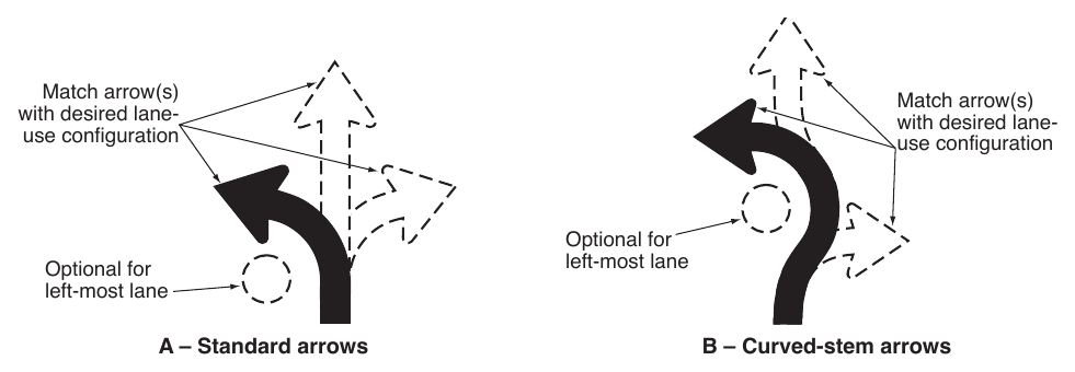
04. If used, the Mandatory Movement Lane Control (R3-7) sign shall be located in advance of the intersection, such as near the upstream end of the mandatory movement lane, and/or at the near side of the intersection where the regulation applies.
Guidance
05. The use of the Mandatory Movement Lane Control (R3-7) word message sign should be limited to only locations that are adjacent to the full-width portion of a mandatory turn lane. The R3-7 sign should not be installed adjacent to a through lane in advance of a turn bay taper or adjacent to a turn bay taper.
06. Mandatory Movement Lane Control signs should be accompanied by lane-use arrow markings, especially where traffic volumes are high, where there is a high percentage of commercial vehicles, or where other distractions exist.
07. Where the restriction does not apply to buses or bicycles an EXCEPT BUSES (R3-7aP) or EXCEPT BICYCLES (R3-7bP) plaque should be used.
Option
08. The Through Only (R3-5a) sign may be used to require a road user in a particular lane to proceed straight through an intersection.
09. The diamond symbol may be used instead of the word message HOV on the R3-5cP supplemental plaque.
10. Where a mandatory left or U-turn lane is added at a median location, a LANE FOR LEFT TURN ONLY (R3-19) or LANE FOR U TURN ONLY (R3-19a) sign may be post-mounted on the median at the beginning of the taper. Where a U turn and a left turn are both allowed, a LANE FOR U AND LEFT TURNS ONLY (R3-19b) sign may be used. Where a R3-19 series sign is used, Mandatory Movement Lane Control signs along the turn lane in the median may be omitted.
11. The R3-19 series signs may be used where the added median turn lane is separated from the through lanes by a channelizing or divisional island.
12. On an approach to a mandatory turn lane where traffic regularly enters the shoulder to access the turn lane inappropriately, creating safety or operational issues, a DO NOT DRIVE ON SHOULDER (R4-17) sign (see Section 2B.43) may be used to supplement the standard Mandatory Movement Lane Control (R3-5 and/or R3-7 series) signs.
§2B.29 Optional Movement Lane Control Signs (R3-6 Series)¶
Standard
01. Optional Movement Lane Control (R3-6, R3-6a and R3-6b) signs (see Figure 2B-4), if used, shall be used for two or more movements from a specific lane or to emphasize permitted movements. The Optional Movement Lane Control sign shall be mounted overhead over the specific lane to which it applies.
02. If used, the Optional Movement Lane Control signs shall indicate all permissible movements from specific lanes.
03. Because more than one movement is permitted from the lane, the word message ONLY shall not be used on an Optional Movement Lane Control sign.
04. Optional Movement Lane Control signs shall be used for two or more movements from a specific lane where a movement, not allowed by State statute or local ordinance, is permitted.
05. The Optional Movement Lane Control signs shall not be used alone to effect a turn prohibition.
Guidance
06. If used, the Optional Movement Lane Control sign should be located overhead in advance of the intersection, such as near the upstream end of an adjacent mandatory movement lane, and/or overhead at the intersection where the regulation applies.
§2B.30 Advance Intersection Lane Control Signs (R3-8 Series)¶
Option
01. Advance Intersection Lane Control (R3-8 Series) signs (see Figure 2B-4) may be used to indicate the configuration of all lanes ahead.
02. The word messages ONLY, THRU, HOV 2+, TAXI, BUS, or BIKE, or the bicycle symbol, may be used within the border in combination with the arrow symbols of the R3-8 sign series. The R3-5cP, R3-5dP, and R3-5gP supplemental plaques may be installed at the top outside border of the R3-8 sign over the applicable lane designation on the sign. The diamond symbol may be used instead of the word message HOV. The minimum allowable vehicle occupancy requirement may vary based on the level established for a particular facility.
03. Where a bicycle lane is between two general-purpose lanes the R3-8 series signs may be modified to show the bicycle lane with a white legend on a black background in accordance with designs of the R3-8x series signs (see Figure 2B-4).
Guidance
04. When used, an Advance Intersection Lane Control sign should be placed at an adequate distance in advance of the intersection, either along the lane tapers or at the beginning of the turn lane so that road users can select the appropriate lane (see Figure 2A-4).
Option
05. An Advance Intersection Lane Control sign may be repeated closer to the intersection along the approach for additional emphasis.
Standard
06. An Advance Intersection Lane Control (R3-8 series) sign shall not be mounted at the far side of an intersection to which it applies.
07. Where three or more approach lanes are available to traffic, Advance Intersection Lane Control (R3-8 series) signs, if used, shall be post-mounted in advance of the intersection and shall not be mounted overhead.
08. When only the two outermost lanes of the roadway are shown on a R3-8 sign, the R3-5bP or R3-5fP plaque shall be mounted above the R3-8 sign.
§2B.31 RIGHT (LEFT) LANE MUST EXIT Signs (R3-33, R3-33a)¶
Option
01. A RIGHT (LEFT) LANE MUST EXIT (R3-33) sign (see Figure 2B-4) may be used to supplement an overhead EXIT ONLY guide sign to inform road users that traffic in the right-hand (left-hand) lane of a roadway that is approaching a grade-separated interchange is required to depart the roadway on the exit ramp at the next interchange.
02. The R3-33a sign (see Figure 2B-4) may be used in place of the R3-33 sign where the roadside width is limited and will not accommodate the R3-33 sign.
Support
03. Section 2C.50 contains information regarding a warning sign that can be used in advance of lane drops at grade-separated interchanges.
§2B.32 Two-Way Left-Turn-Only Signs (R3-9a and R3-9b) and Plaques¶
Guidance
01. A Two-Way Left-Turn-Only (R3-9a or R3-9b) sign (see Figure 2B-6) should be used in conjunction with the required pavement markings where a non-reversible lane is reserved for the exclusive use of left-turning vehicles in either direction and is not used for passing, overtaking, or through travel.
Option
02. The post-mounted R3-9b sign may be used as an alternate to or a supplement to the overhead R3-9a sign. The legend BEGIN or END may be used within the border of the main sign itself, or on an R3-9cP or R3-9dP plaque (see Figure 2B-6) mounted immediately above it.
Support
03. Signing is especially helpful to drivers in areas where the two-way left-turn-only maneuver is new, in areas subject to environmental conditions that frequently obscure the pavement markings, and on peripheral streets with two-way left-turn-only lanes leading to an extensive system of routes with two-way left-turn-only lanes.
§2B.33 BEGIN and END Plaques (R3-9cP and R3-9dP)¶
Option
01. The BEGIN (R3-9cP) or END (R3-9dP) plaque (see Figure 2B-6), mounted directly above a regulatory sign, may be used to inform road users of the location where a regulatory condition begins or ends.
§2B.34 Reversible Lane Control Signs (R3-9e through R3-9i)¶
Option
01. A reversible lane may be used for through traffic (with left turns either permitted or prohibited) in alternating directions during different periods of the day, and the lane may be used for exclusive left turns in one or both directions during other periods of the day as well. Reversible Lane Control (R3-9e through R3-9i) signs (see Figure 2B-6) may be either static type or changeable message type. These signs may be either post-mounted or overhead. Lane-use control signals (see Chapter 4T) may also be used for reversible lanes.
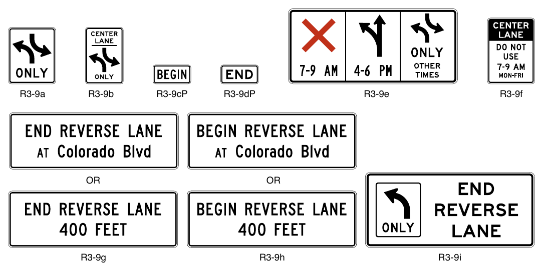
Signs shown: R3-9a, R3-9b, R3-9cP, R3-9dP, R3-9e, R3-9f, R3-9g, R3-9h, R3-9i
Standard
02. Where it is determined by an engineering study that lane-use control signals or physical barriers are not necessary, the lane shall be controlled by overhead Reversible Lane Control signs (see Figure 2B-7).
03. Post-mounted Reversible Lane Control signs shall be used only as a supplement to overhead signs or signals. Post-mounted signs shall be identical in design to the overhead signs and an additional legend such as CENTER LANE shall be added to the top of the sign (R3-9f) to indicate which lane is controlled.
Option
04. Reversing traffic flow may be controlled with pavement markings and Reversible Lane Control signs (without the use of lane-use control signals), when all of the following conditions are met:
- A. Only one lane is being reversed,
- B. An engineering study indicates that the use of Reversible Lane Control signs alone would result in an acceptable level of safety and efficiency, and
- C. There are no unusual or complex operations in the reversible lane pattern.
Standard
05. Reversible Lane Control signs shall contain the legend or symbols designating the allowable uses of the lane and the time periods such uses are allowed. Where symbols and legends are used, their meanings shall be as shown in Table 2B-2.
06. Reversible Lane Control signs shall consist of a white background with a black legend and border, except for the R3-9e sign, where the color red is used for the X symbol.
07. Symbol signs, such as the R3-9e sign, shall consist of the appropriate symbol in the upper portion of the sign with the appropriate times of the day and days of the week below it. All times of the day and days of the week shall be accounted for on the sign to eliminate confusion to the road user.
Table 2B-2. Meanings of Symbols and Legends on Reversible Lane Control Signs
| Symbol / Word Message | Meaning |
|---|---|
| Red X on white background | Lane closed |
| Upward-pointing black arrow on white background (if left turns are permitted, the arrow shall be modified to show left / through arrow) | Lane open for through travel and any turns not otherwise prohibited |
| Black two-way left-turn arrows on white background and legend ONLY | Lane may be used only for left turns in either direction (i.e., as a two-way left-turn lane) |
| Black single left-turn arrow on white background and legend ONLY | Lane may be used only for left turns in one direction (without opposing left turns in the same lane) |
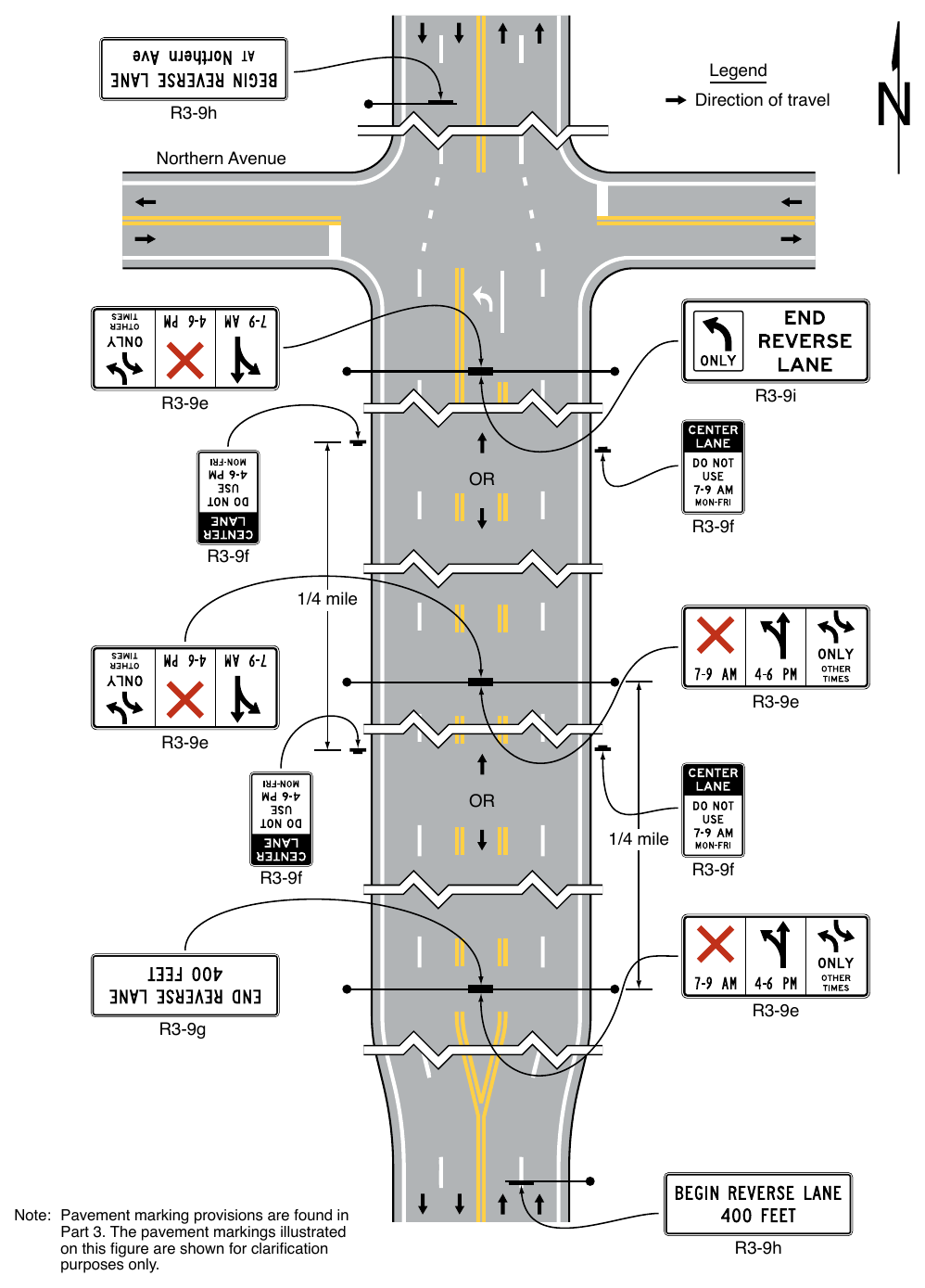
08. Note: Pavement marking provisions are found in Part 3. The pavement markings illustrated on this figure are shown for clarification purposes only. R3-9f R3-9e R3-9h In situations where more than one message is conveyed to the road user, such as on the R3-9e sign, the sign legend shall be arranged as follows:
- A. The prohibition or restriction message is the primary legend and shall be on the top for word message signs and to the far left for symbol signs,
- B. The permissive use message shall be displayed as the second legend, and
- C. The OTHER TIMES message shall be displayed at the bottom for word message signs and to the far right for symbol signs.
Option
09. The symbol signs may also include a downward-pointing arrow with the legend THIS LANE. The term OTHER TIMES may be used for either the symbol or word message sign.
Standard
10. A Reversible Lane Control sign shall be mounted over the approximate center of the lane that is being reversed.
11. If the vertical or horizontal alignment is curved to the degree that a driver would be unable to see at least one sign, and preferably two signs, then additional overhead signs shall be installed. The placement of the signs shall be such that the driver will have a definite indication of the lanes specifically reserved for use at any given time. Special consideration shall be given to major generators introducing traffic between the normal sign placement.
12. Transitions at the entry to and exit from a section of roadway with reversible lanes shall include advance signs to notify or warn drivers of the boundaries of the reversible lane controls. The R3-9g or R3-9h signs (see Figure 2B-6) shall be used for this purpose.
Option
13. More than one End Reverse Lane (R3-9i) sign (see Figure 2B-6) may be used at the termination of the reversible lane to emphasize the importance of the message.
14. Where longitudinal barriers separate opposing directions of traffic, the R3-9g or R3-9h signs may be omitted.
Standard
15. Flashing beacons, if used to supplement the overhead Reversible Lane Control signs, shall comply with the applicable requirements for flashing beacons in Chapter 4S.
16. When used in conjunction with Reversible Lane Control signs, the Turn Prohibition (R3-1 through R3-4 and R3-18) signs shall be mounted overhead and separate from the Reversible Lane Control signs. The Turn Prohibition signs shall be designed and installed in accordance with Section 2B.26.
Guidance
17. For additional emphasis, a supplemental plaque stating the distance of the prohibition, such as NEXT 1 MILE, should be added to the Turn Prohibition signs that are used in conjunction with Reversible Lane Control signs.
18. If used, overhead signs should be located at intervals not greater than ¼ mile. The bottom of the overhead Reversible Lane Control signs should not be more than 19 feet above the pavement grade.
19. Where more than one sign is used at the termination of a reversible lane, they should be at least 250 feet apart. Longer distances between signs are appropriate for streets with speeds over 35 mph, but the separation should not exceed 1,000 feet.
20. Because left-turning vehicles have a significant impact on the safety and efficiency of a reversible lane operation, if a mandatory left-turn lane or two-way left-turn lane cannot be incorporated into the lane-use pattern for a particular peak or off-peak period, consideration should be given to prohibiting left turns and U-turns during that time period.
21. Reversible Lane Control signs and parking signs should be consistent in message during the same operational periods.
§2B.35 Jughandle Signs (R3-23, R3-24, R3-25, and R3-26 Series)¶
Support
01. A jughandle turn is a left turn or U-turn that because of special geometry is made by initially making a right turn. This type of turn can increase the operational efficiency of a roadway by eliminating the need for mandatory left-turn lanes and can increase the operational efficiency of a traffic control signal by eliminating the need for protected left-turn phases. A jughandle turn can also provide an opportunity for trucks and commercial vehicles to make a U-turn where the median and roadway are not of sufficient width to accommodate a traditional U-turn by these vehicles.
02. Figure 2B-8 shows the various signs that can be used for signing jughandle turns. Figure 2B-9 shows examples of regulatory and destination guide signing for various types of jughandle turns.
Standard
03. On multi-lane roadways, since road users generally anticipate that they need to be in the left-hand lane when approaching a location where they desire to turn left or make a U-turn, an ALL TURNS FROM RIGHT LANE (R3-23) or a U TURN FROM RIGHT LANE (R3-23a) sign (see Figure 2B-8) shall be installed in advance of the location to inform drivers that left turns and/or U-turns will be made from the right-hand lane.
Option
04. Where a median of sufficient width is available, supplemental regulatory or guide signs may also be placed on the left-hand side of the roadway.
Standard
05. The R3-24 series sign with an upward diagonal arrow pointing to the right if the jughandle entrance is designed as an exit ramp (see Drawings A and B in Figure 2B-9), or the R3-25 series sign with a horizontal arrow pointing to the right if the jughandle entrance is designed as an intersection, shall be installed on the right-hand side of the roadway at the entrance to the jughandle. The legend on the sign shall be ALL TURNS, U TURN, or U AND LEFT TURNS, as appropriate.
06. If the jughandle is designed such that the jughandle entrance is downstream of the location where the turn would normally have been made (see Drawing C in Figure 2B-9), the R3-26 series sign with an arrow pointing straight upward shall be installed on the right-hand side of the roadway at the intersection to inform road users that they need to proceed straight through the intersection in order to make a left turn or U-turn. The legend on the sign shall be U TURN or U AND LEFT TURNS, as appropriate.
Support
07. The R3-24, R3-25, and R3-26 series of signs are designed to be mounted below conventional guide signs.
08. Section 2C.12 contains information regarding the use of advisory exit and ramp speed signs for exit ramps.
09. Section 2D.40 contains information regarding the use of guide signs for jughandles.
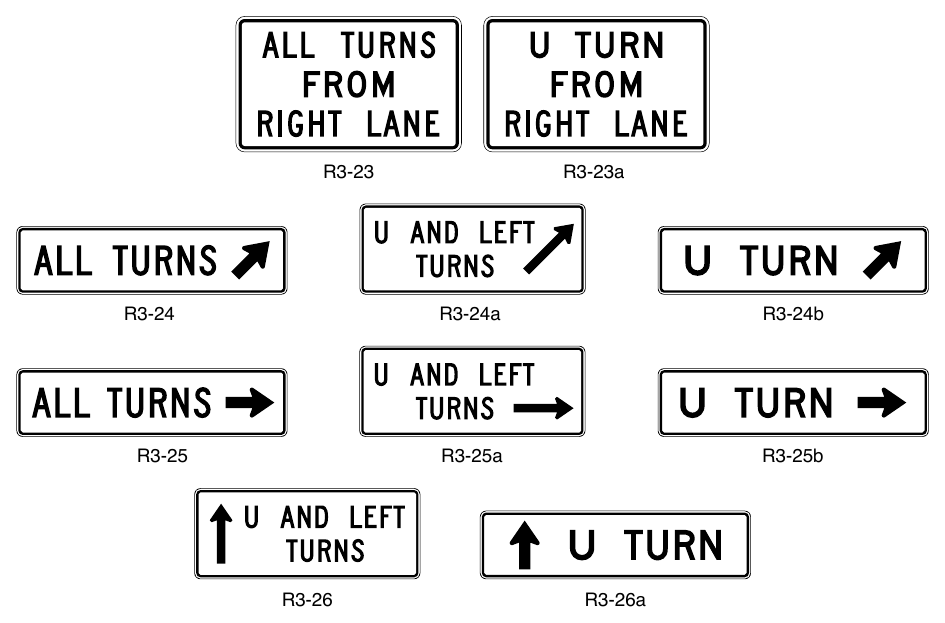
Signs shown: R3-23, R3-23a, R3-24, R3-24a, R3-24b, R3-25, R3-25a, R3-25b, R3-26, R3-26a
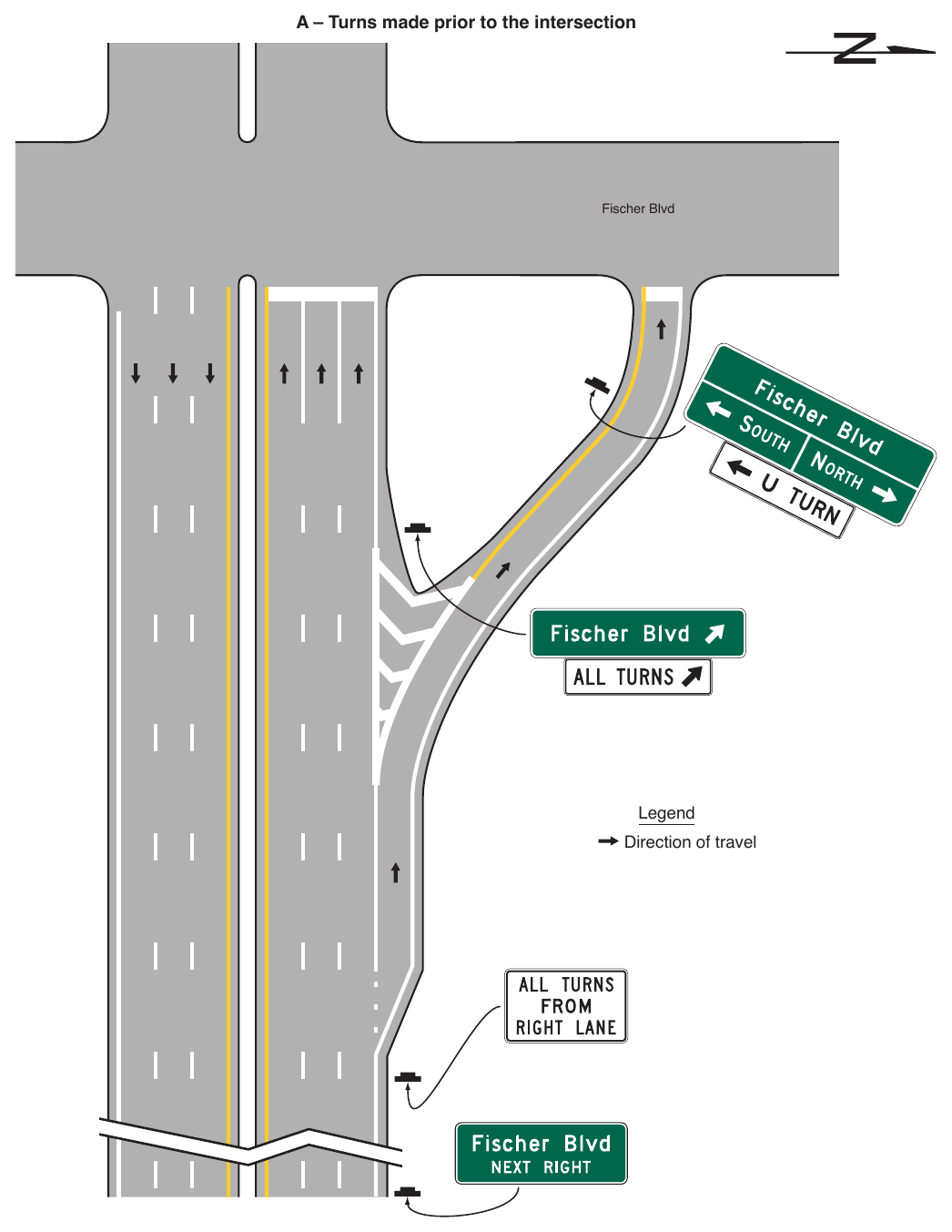
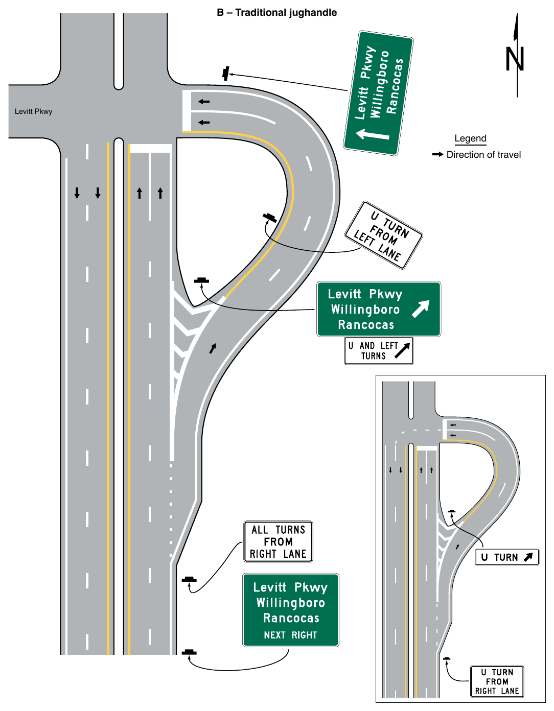
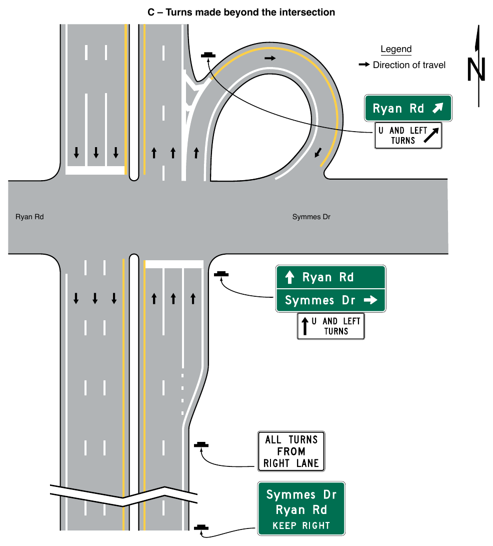
PASSING, KEEP RIGHT, AND SLOW TRAFFIC SIGNS¶
§2B.36 DO NOT PASS Sign (R4-1)¶
Option
01. The Do Not Pass (R4-1) sign (see Figure 2B-10) may be used in addition to pavement markings (see Section 3B.03) to emphasize the restriction on passing. The Do Not Pass sign may be used at the beginning of, and at intervals within, a zone through which sight distance is restricted or where other conditions make overtaking and passing inappropriate.
02. If signing is needed on the left-hand side of the roadway for additional emphasis, NO PASSING ZONE (W14-3) signs may be used (see Section 2C.53).
Support
03. Standards for determining the location and extent of no-passing zone pavement markings are set forth in Section 3B.03.
§2B.37 PASS WITH CARE Sign (R4-2)¶
Guidance
The PASS WITH CARE (R4-2) sign (see Figure 2B-10) should be installed at the downstream end of a no-passing zone if a Do Not Pass sign has been installed at the upstream end of the zone.
§2B.38 KEEP RIGHT EXCEPT TO PASS Sign (R4-16), SLOWER TRAFFIC KEEP RIGHT¶
Sign (R4-3), and TRUCKS USE RIGHT LANE Sign (R4-5)
Option
01. The KEEP RIGHT EXCEPT TO PASS (R4-16) sign (see Figure 2B-10) may be used on roadways where there are two lanes in one direction of travel to direct drivers to stay in the right-hand lane except when they are passing another vehicle.
Guidance
02. If used, the KEEP RIGHT EXCEPT TO PASS sign should be installed at or just beyond the beginning of a two-lane section of roadway and at selected locations along two-lane roadways where additional emphasis is needed.
Option
03. The SLOWER TRAFFIC KEEP RIGHT (R4-3) or the TRUCKS USE RIGHT LANE (R4-5) sign (see Figure 2B-10) may be used on multi-lane through roadways to improve capacity or reduce unnecessary lane changing due to the presence of slower vehicles that impede the normal flow of traffic.
Guidance
04. If used, the SLOWER TRAFFIC KEEP RIGHT sign or the TRUCKS USE RIGHT LANE sign should be installed at or just beyond the beginning of a multi-lane roadway section or at the beginning of an extra lane provided for trucks and/or other slow-moving traffic, and at selected locations where there is a tendency on the part of some road users to drive in the left-hand lane(or lanes) below the normal speed of traffic. These signs should not be used on the approach to an interchange or through an interchange area where traffic is entering or exiting, or along deceleration or acceleration lanes.
Option
05. The TRUCKS USE RIGHT LANE sign may be used as a supplement to the SLOWER TRAFFIC KEEP RIGHT sign.
Guidance
06. If an extra lane has been provided for trucks and other slow-moving traffic, a Lane Ends sign (see Section 2C.47) should be installed in advance of the point where the extra lane ends. Appropriate pavement markings should be installed at both the upstream and downstream ends of the extra lane (see Section 3B.12 and Figure 3B-14).
§2B.39 Keep Right and Keep Left Signs (R4-7 Series and R4-8 Series)¶
Option
01. The Keep Right (R4-7) sign (see Figure 2B-10) may be used at locations where it is necessary for traffic to pass only to the right-hand side of a roadway feature or obstruction. The Keep Left (R4-8) sign (see Figure 2B-10) may be used at locations where it is necessary for traffic to pass only to the left-hand side of a roadway feature or obstruction.
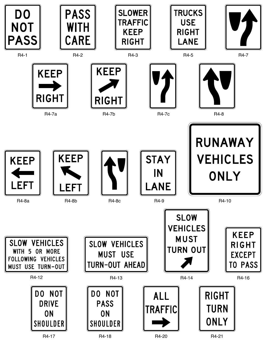
Signs shown: R4-1, R4-2, R4-3, R4-5, R4-7, R4-7b, R4-7a, R4-7c, R4-8, R4-8a, R4-8b, R4-8c, R4-9, R4-10, R4-12, R4-13, R4-14, R4-16, R4-17, R4-18, R4-20, R4-21
Guidance
02. At locations where it is not readily apparent that traffic is required to keep to the right, a Keep Right sign should be used.
Standard
03. If Keep Right signs are installed at the start of a median or at a median opening, they shall be placed as close as practicable to the approach ends of the medians, and shall be visible to traffic on the divided highway and angled toward the applicable crossroad approach as shown in Figure 2B-20.
Guidance
04. If used, the Keep Right sign should be mounted on the face of or just in front of a pier or other obstruction separating opposite directions of traffic in the center of the highway such that traffic will have to pass to the right-hand side of the sign.
05. Where the approach end of the island channelizes traffic away from the approach direction, the word legend (R4-7a, R4-7b, R4-8a, or R4-8b) signs (see Figure 2B-10) should be used instead of the symbol (R4-7 or R4-8) signs to emphasize the degree of curvature away from the approach direction (see Figure 2B-11).
06. Where a regulatory sign is used within the central island of a neighborhood traffic circle to direct traffic counter-clockwise around the central island, the Keep Right with diagonal arrow (R4-7b) sign should be used (see Figure 2B-24). The mounting height of the sign should be at least 4 feet, measured vertically from the bottom of the sign to the elevation of the near edge of the traveled way.
Standard
07. The Keep Right (Left) sign shall not be installed on the right-hand (left-hand) side of the roadway in a position where traffic must pass to the left-hand (right-hand) side of the sign.
Option
08. The Keep Right sign may be omitted at intermediate ends of divisional islands and medians.
09. Word message KEEP RIGHT (LEFT) with an arrow (R4-7a or R4-7b) signs (see Figure 2B-10) may be used instead of the R4-7 or R4-8 symbol signs.
10. A narrow Keep Right (R4-7c) sign (see Figure 2B-10) may be installed on the approach end of a median island that is less than 4 feet wide at the point where the sign is to be located.
Standard
11. A narrow Keep Right (R4-7c) sign shall not be installed on a median island that has a width of 4 feet or more at the point where the sign is to be located.
Option
12. The Keep Right sign may be installed in the median of a divided highway crossing that functions as a single intersection such that it is visible to traffic on the divided highway and angled as needed toward the applicable crossroad approach as shown in Figure 2B-20.
Support
13. Section 2B.49 provides more information about the use of the Keep Right sign in combination with or in lieu of ONE-WAY signs at divided highway crossings.
§2B.40 STAY IN LANE Sign (R4-9)¶
Option
01. A STAY IN LANE (R4-9) sign (see Figure 2B-10) may be used on multi-lane highways to direct road users to stay in their lane until conditions permit shifting to another lane.
Guidance
02. If a STAY IN LANE sign is used, it should be accompanied by a solid double white lane line(s) to prohibit lane changing.
§2B.41 RUNAWAY VEHICLES ONLY Sign (R4-10)¶
Guidance
01. A RUNAWAY VEHICLES ONLY (R4-10) sign (see Figure 2B-10) should be installed near a truck escape (or runaway truck) ramp entrance to discourage other road users from entering the ramp.
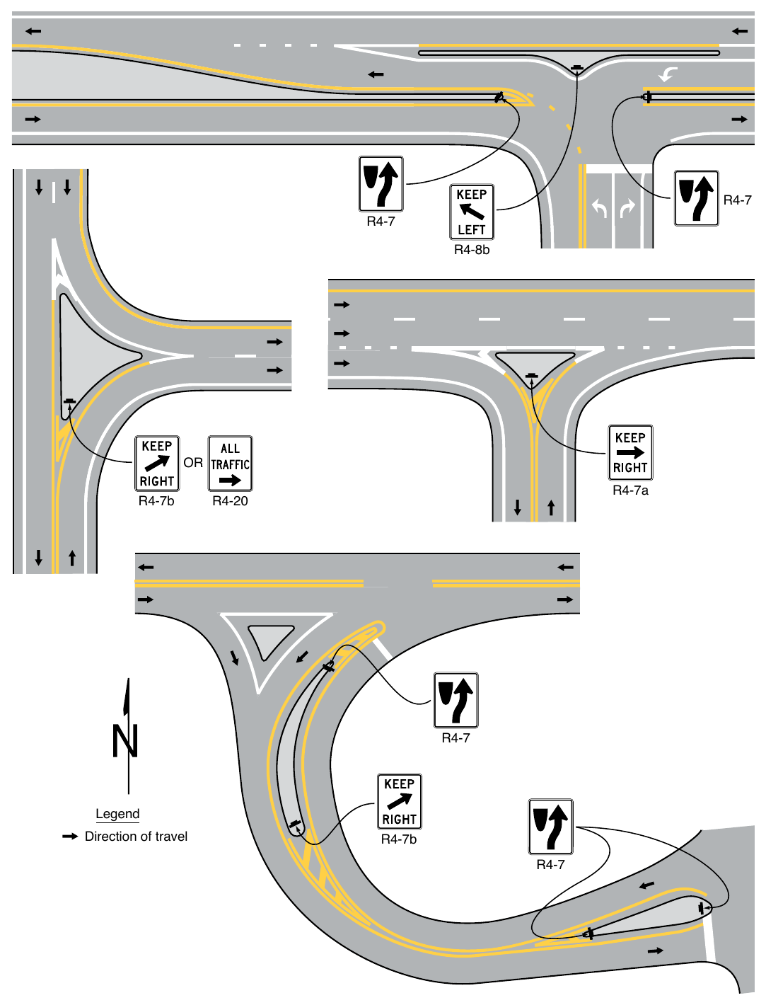
§2B.42 Slow Vehicle Turn-Out Signs (R4-12, R4-13, and R4-14)¶
Support
01. On two-lane highways in areas where traffic volumes and/or vertical or horizontal curvature make passing difficult, turn-out areas are sometimes provided for the purpose of giving a group of faster vehicles an opportunity to pass a slow-moving vehicle.
Option
02. A SLOW VEHICLES WITH XX OR MORE FOLLOWING VEHICLES MUST USE TURN-OUT (R4-12) sign (see Figure 2B-10) may be installed in advance of a turn-out area to inform drivers who are driving so slow that they have accumulated a specific number of vehicles behind them that they are required by the traffic laws of that State to use the turn-out to allow the vehicles following them to pass.
Support
03. The specific number of vehicles displayed on the R4-12 sign provides law enforcement personnel with the information they need to enforce this regulation.
Option
04. If an R4-12 sign has been installed in advance of a turn-out area, a SLOW VEHICLES MUST USE TURNOUT AHEAD (R4-13) sign (see Figure 2B-10) may also be installed downstream from the R4-12 sign, but upstream from the turn-out area, to remind slow drivers that they are required to use a turn-out that is a short distance ahead.
Standard
05. If an R4-12 sign has been installed in advance of a turn-out area, a SLOW VEHICLES MUST TURN OUT (with arrow) (R4-14) sign (see Figure 2B-10) shall be installed at the entry point of the turn-out area.
Support
06. Section 2D.54 contains information regarding advance information signs for slow vehicle turn-out areas.
§2B.43 DO NOT DRIVE ON SHOULDER Sign (R4-17) and DO NOT PASS ON SHOULDER Sign (R4-18)¶
Option
01. The DO NOT DRIVE ON SHOULDER (R4-17) sign (see Figure 2B-10) may be installed to inform road users that using the shoulder of a roadway as a travel lane is prohibited.
02. The DO NOT PASS ON SHOULDER (R4-18) sign (see Figure 2B-10) may be installed to inform road users that using the shoulder of a roadway to pass other vehicles is prohibited.
§2B.44 ALL TRAFFIC Sign (R4-20) and RIGHT (LEFT) TURN ONLY Sign (R4-21)¶
Option
01. The ALL TRAFFIC (R4-20) sign may be used at an intersection where all traffic on the approach to the intersection must turn in the direction indicated and the Movement Prohibition (see Section 2B.26) and/or ONE WAY (see Section 2B.49) signs do not adequately convey the allowable direction of travel.
02. The RIGHT (LEFT) TURN ONLY (R4-21) sign may be used at or on an approach to an intersection where all traffic on that approach must turn in the direction indicated.
Guidance
03. The RIGHT (LEFT) TURN ONLY sign should not be used for a channelized turn lane separated from the adjacent travel lanes by an island.
Standard
04. The ALL TRAFFIC sign shall not be used to substitute for the Keep Right (R4-7 series) or Keep Left (R4-8 series) signs.
05. The RIGHT (LEFT) TURN ONLY sign shall not be used to substitute for the Mandatory Movement Lane Control signs (see Sections 2B.27 and 2B.28).
SELECTIVE EXCLUSION SIGNS AND PLAQUES¶
§2B.45 Selective Exclusion Signs and Plaques¶
Option
01. Selective Exclusion signs (see Figure 2B-12) may be used to provide notice to road users that State or local statutes or ordinances exclude designated types of traffic from using particular roadways or facilities.
Standard
02. Selective Exclusion signs shall clearly indicate the type of traffic that is excluded.
Support
03. Typical exclusion messages include:
- A. No Trucks (R5-2),
- B. NO MOTOR VEHICLES (R5-3),
- C. NO COMMERCIAL VEHICLES (R5-4),
- D. NO VEHICLES WITH LUGS (R5-5),
- E. No Bicycles (R5-6),
- F. NO NON-MOTORIZED TRAFFIC (R5-7),
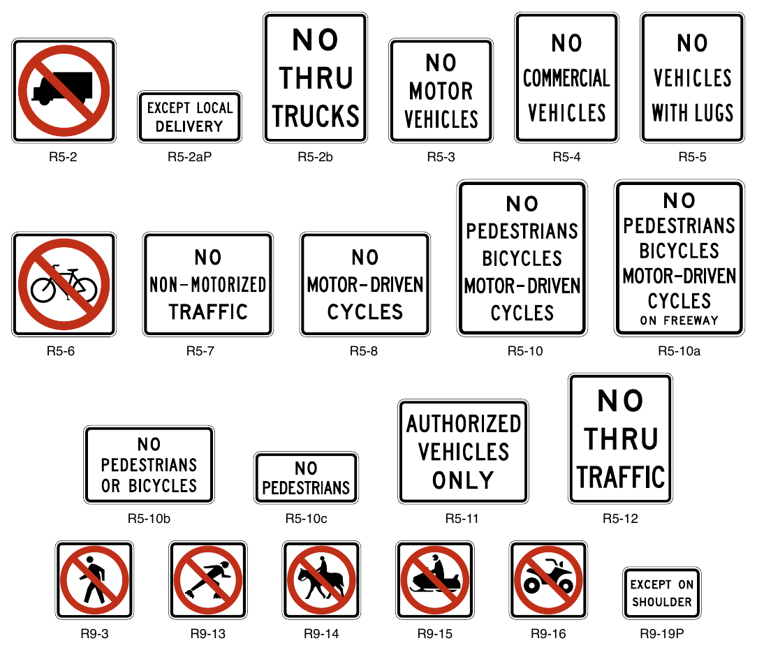
Signs shown: R5-2, R5-2aP, R5-2b, R5-3, R5-4, R5-5, R5-6, R5-7, R5-8, R5-10, R5-10a, R5-10b, R5-10c, R5-11, R5-12, R9-3, R9-13, R9-14, R9-15, R9-16, R9-19P
- H. No Pedestrian Crossing (R9-3),
- I. No Skaters (R9-13),
- J. No Equestrians (R9-14),
- K. No Snowmobiles (R9-15),
- L. No All-Terrain Vehicles (R9-16),
- M. Hazardous Material (R14-3) (see Section 2B.67),
- N. NO THRU TRAFFIC (R5-12),
- O. NO THRU TRUCKS (R5-2b),
- P. EXCEPT ON SHOULDER (R9-19P) plaque, and
- Q. EXCEPT LOCAL DELIVERY (R5-2aP) plaque.
Option
04. Appropriate combinations or groupings of these legends into a single sign, such as NO PEDESTRIANS BICYCLES MOTOR-DRIVEN CYCLES (R5-10 and R5-10a) or NO PEDESTRIANS OR BICYCLES (R5-10b), may be used.
Guidance
05. If an exclusion is governed by vehicle weight, a Weight Limit sign (see Section 2B.64) should be used instead of a Selective Exclusion sign.
06. If used on a ramp to a freeway or expressway where pedestrian and bicyclist travel are prohibited by law or regulation, the NO PEDESTRIANS OR BICYCLES (R5-10b) sign should be installed in a location where it is clearly visible to any pedestrian or bicyclist attempting to enter the limited access facility from a street intersecting the ramp. In locations where a freeway or expressway is accessed from a ramp from a roadway parallel to the freeway or expressway, the sign should be placed in a location that clearly indicates the prohibition applies only to the freeway or expressway or to the ramp.
07. The Selective Exclusion sign should be placed on the right-hand side of the roadway at an appropriate distance from the intersection so as to be clearly visible to all road users turning into the roadway that has the exclusion. The NO PEDESTRIANS (R5-10c) or No Pedestrian Crossing (R9-3) sign (see Section 2B.57) should be installed so as to be clearly visible to pedestrians who are at a location where an alternative route is available.
Option
08. The NO PEDESTRIANS (R5-10c) or No Pedestrian Crossing (R9-3) sign may also be used at underpasses or elsewhere where pedestrian facilities are not provided.
09. The NO THRU TRAFFIC (R5-12) or NO THRU TRUCKS (R5-2b) signs may be used at locations to prohibit through traffic from using a particular roadway or facility.
10. The EXCEPT LOCAL DELIVERY (R5-2aP) plaque may be mounted below the R5-2 or R5-2b sign.
11. The EXCEPT ON SHOULDER (R9-19P) plaque may be used where such modes are allowed on a shoulder but not on the traveled way and placed at intersections with other roads and established paths or trails, where such vehicles or modes are expected to enter the highway.
12. The AUTHORIZED VEHICLES ONLY (R5-11) sign may be used at median openings and other locations to prohibit vehicles from using the median opening or facility unless they have special permission (such as law enforcement vehicles or emergency vehicles) or are performing official business (such as highway agency vehicles).
DO NOT ENTER, WRONG WAY, ONE WAY, AND RELATED SIGNS AND PLAQUES¶
§2B.46 DO NOT ENTER Sign (R5-1)¶
Standard
01. The DO NOT ENTER (R5-1) sign (see Figure 2B-13) shall be used at the following locations:
- A. Where a two-way roadway becomes a one-way roadway (see Figure 2B-18);
- B. The intersection of an interchange exit ramp with a crossroad as specified in Section 2B.48 (see Figure 2B-15);
- C. The intersection of a channelized or turning roadway with a two-way undivided crossroad; and
- D. Except as provided in Paragraph 4 of this Section, an intersection with a divided highway where the crossing functions as two separate intersections (see Figure 2B-14).
Guidance
02. A DO NOT ENTER sign should be installed at other locations where additional emphasis is needed where wrong-way movements are prominent or where the intersecting angle of roadways is such that the visibility of ONE WAY signs alone does not sufficiently convey the restriction.
Option
03. A DO NOT ENTER sign may be installed at an intersection with a divided highway where the crossing functions as a single intersection as shown in Figure 2B-20.
04. A DO NOT ENTER sign may be omitted on a low-speed urban street that is a divided highway at a crossing that functions as two separate intersections.
05. An EXCEPT BICYCLES (R3-7bP) plaque (see Figure 2B-4) may be used with a DO NOT ENTER sign when counter-flow bicycle traffic is allowed.
Guidance
06. The DO NOT ENTER sign, if used, should be placed directly in view of a road user at the point where a road user could wrongly enter a divided highway, one-way roadway, or ramp. The sign should be mounted facing traffic that might enter the roadway or ramp in the wrong direction.
07. At a crossing with a divided highway that functions as a single intersection; the sign, if used, should be placed on the outside edge side of the roadway facing traffic that might enter the roadway in the wrong direction.
08. If the DO NOT ENTER sign would be visible to traffic to which it does not apply, the sign should be turned away from, or shielded from, the view of that traffic.
Option
09. A second DO NOT ENTER sign may be used, particularly where traffic approaches from an intersecting roadway (see Figure 2B-14).
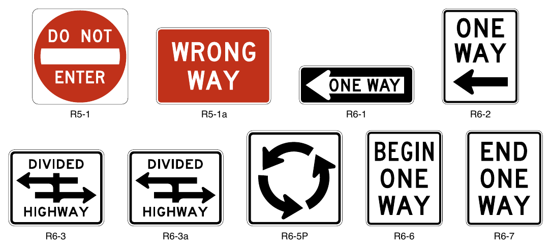
Signs shown: R5-1, R5-1a, R6-1, R6-2, R6-3, R6-3a, R6-5P, R6-6, R6-7
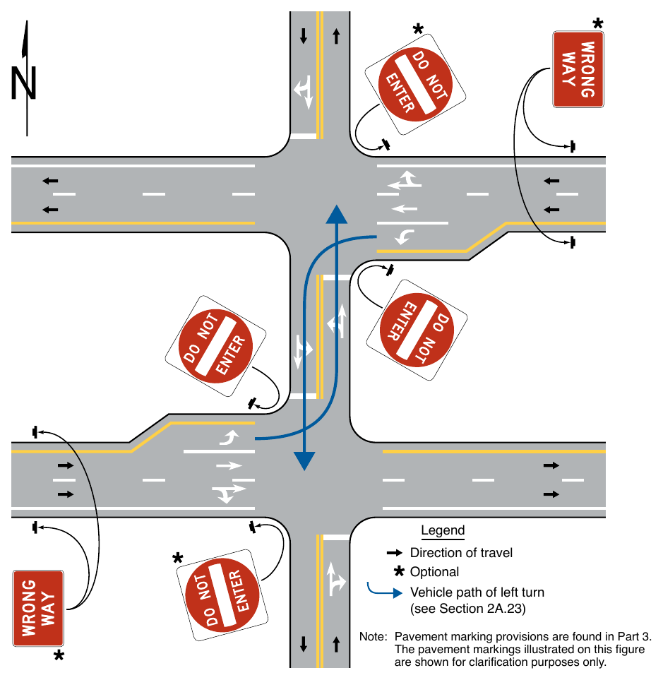
(see Section 2A.23) Note: Pavement marking provisions are found in Part 3. The pavement markings illustrated on this figure are shown for clarification purposes only.
Support
10. Section 2B.48 contains information regarding an optional lower mounting height for DO NOT ENTER signs that are located along an exit ramp facing a road user who is traveling in the wrong direction.
11. Section 2A.12 contains the provisions for the use of continuously-operated or actuated LEDs to enhance the conspicuity of signs.
§2B.47 WRONG WAY Sign (R5-1a)¶
Option
01. The WRONG WAY (R5-1a) sign (see Figure 2B-13) may be used as a supplement to the DO NOT ENTER sign where a crossroad intersects a one-way roadway in a manner that does not physically discourage or prevent wrong-way entry (see Figures 2B-14 and 2B-20).
Guidance
02. If used, the WRONG WAY sign should be placed at a location along the one-way roadway farther from the crossroad than the DO NOT ENTER sign (see Section 2B.46).
03. The WRONG WAY sign should be placed on the same side of the road as the DO NOT ENTER sign.
Support
04. Section 2B.48 contains information regarding an optional lower mounting height for WRONG WAY signs that are located along an exit ramp facing a road user who is traveling in the wrong direction.
05. Section 2A.12 contains the provisions for the use of continuously-operated or actuated LEDs to enhance the conspicuity of signs.
§2B.48 Wrong-Way Traffic Control at Interchange Ramps¶
Standard
01. At interchange exit ramp terminals where the ramp intersects a crossroad in such a manner that wrong-way entry could inadvertently be made, the following signs shall be used (see Figure 2B-15):
- A. At least one ONE WAY sign for each direction of travel on the crossroad shall be placed where the exit ramp intersects the crossroad.
- B. At least one DO NOT ENTER sign shall be conspicuously placed near the downstream end of the exit ramp in positions appropriate for full view of a road user starting to enter wrongly from the crossroad.
- C. At least one WRONG WAY sign shall be placed on the exit ramp facing a road user traveling in the wrong direction.
Guidance
02. In addition, the following pavement markings should be used (see Figure 2B-15):
- A. On two-lane paved crossroads at interchanges, solid double yellow lines should be used as a center line for an adequate distance on both sides approaching the ramp intersections.
- B. Where crossroad channelization or ramp geometrics do not make wrong-way movements difficult, a laneuse arrow should be placed in each lane of an exit ramp near the crossroad terminal where it will be clearly visible to a potential wrong-way road user.
Option
03. The following traffic control devices may be used to supplement the signs and pavement markings described in Paragraphs 1 and 2 of this Section:
- A. Additional ONE WAY signs may be placed, especially on two-lane rural crossroads, appropriately in advance of the ramp intersection to supplement the required ONE WAY sign(s).
- B. Additional WRONG WAY signs may be used.
- C. Slender, elongated wrong-way arrow pavement markings (see Figure 3B-21) intended primarily to warn wrong-way road users that they are traveling in the wrong direction may be placed upstream from the ramp terminus (see Figure 2B-15) to indicate the correct direction of traffic flow. Wrong-way arrow pavement markings may also be placed on the exit ramp at appropriate locations near the crossroad junction to indicate wrong-way movement. The wrong-way arrow markings may consist of pavement markings or bidirectional red-and-white raised pavement markers or other units that show red to wrongway road users and white to other road users.
- D. Lane-use arrow pavement markings may be placed on the exit ramp and crossroad near their intersection to indicate the permissive direction of flow.
- E. Freeway entrance signs (see Section 2D.50) may be used.
- F. Lane control signs or movement prohibition signs may be used on the approaches to the exit ramp.
- G. A Keep Right (R4-7 or R4-7c) may be used on a ramp median nose for wrong-way traffic control.
Guidance
04. On interchange entrance ramps where the ramp merges with the through roadway and the design of the interchange does not clearly make evident the direction of traffic on the separate roadways or ramps, a ONE WAY sign visible to traffic on the entrance ramp and through roadway should be placed on each side of the through roadway near the entrance ramp merging point as illustrated in Figure 2B-16.
Option
05. On interchange entrance ramps where the ramp merges with the through roadway and the design of the interchange does not clearly make evident the direction of traffic on the separate roadways or ramps a No Left Turn (R3-2) sign may be located on the left-hand side of the entrance ramp at the gore (see Figure 2B-16). If a No Left Turn (R3-2) sign is located on the left-hand side a supplemental R3-2 sign may be installed on the right-hand side of the entrance ramp.
06. On interchange entrance ramps where the ramp merges with the through roadway and the design clearly indicates the direction of flow, a ONE WAY sign may be placed visible to traffic on the entrance ramp and/or a NO TURNS (R3-3) sign may be placed visible to traffic on the entrance ramp and through roadway at the gore area as illustrated in Figure 2B-16.
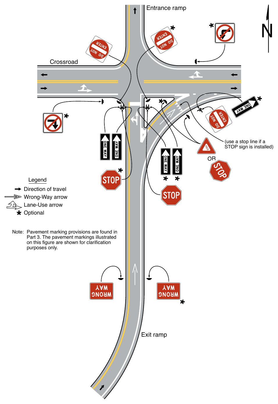
Note: Pavement marking provisions are found in Part 3. The pavement markings illustrated on this figure are shown for clarification purposes only. Exit ramp
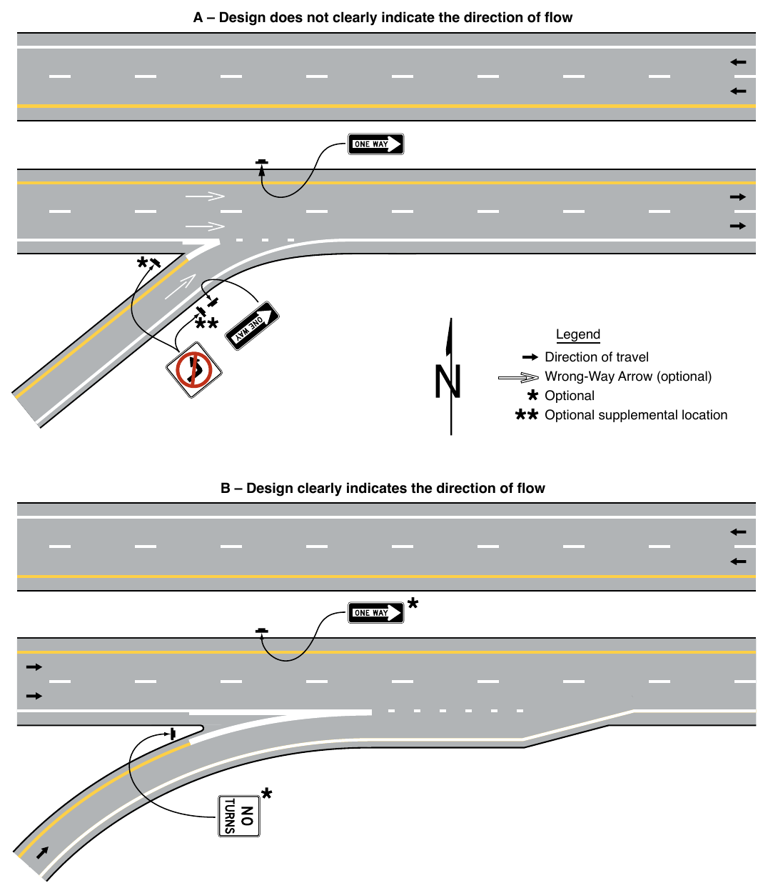
Where there are no parked cars, pedestrian activity, or other obstructions such as snow or vegetation, and if an engineering study indicates that a lower mounting height would address wrong-way movements on freeway or expressway exit ramps, a DO NOT ENTER sign(s) and/or a WRONG WAY sign(s) that is located along the exit ramp at a location downstream from the intersection with the crossroad facing a road user who is traveling in the wrong direction may be installed at a minimum mounting height of 3 feet, measured vertically from the bottom of the sign to the elevation of the near edge of the pavement. At the intersection with the crossroad, a WRONG WAY sign may be mounted at a minimum height of 3 feet on the same support on which a DO NOT ENTER sign is mounted at a height that complies with the provisions of Section 2A.15 (see Figure 2B-17).
Support
08. Sections 2B.46, 2B.47, and 2B.49 contain further information on signing to avoid wrong-way movements at at-grade intersections on expressways.
§2B.49 ONE WAY Signs (R6-1 and R6-2)¶
Standard
01. Except as provided in Paragraph 6 of this Section, the ONE WAY (R6-1 or R6-2) sign (see Figure 2B-13) shall be used to indicate streets or roadways upon which vehicular traffic is allowed to travel in one direction only.
02. ONE WAY signs shall be placed parallel to the one-way street at all alleys and roadways that intersect one-way roadways as shown in Figure 2B-18.
03. At the crossing of a roadway with a divided highway that functions as two separate intersections, ONE WAY signs shall be placed, visible to each crossroad approach, on the near right and far left corners of each intersection with the directional roadways (see Figure 2B-19).
04. At the crossing of a roadway with a divided highway that functions as a single intersection Keep Right (R4-7) signs (see Section 2B.39) and/or ONE WAY signs shall be installed (see Figure 2B-20). If Keep Right signs are installed, they shall be placed as close as practicable to the approach ends of the medians and shall be visible to traffic on the divided highway and angled (as needed) toward the applicable crossroad approach as shown in Figure 2B-20. If ONE WAY signs are installed, they shall be placed on the near right and far left corners of the intersection and shall be visible to each crossroad approach.
Option
05. At the crossing of a roadway with a divided highway, regardless of function as a single or separate intersections, ONE WAY signs may also be placed on the far right corner of the intersection as shown in Figures 2B-19 and 2B-20.
06. ONE WAY signs may be omitted on the one-way roadways of divided highways, where the design of interchanges indicates the direction of traffic on the separate roadways.
07. An EXCEPT BICYCLES (R3-7bP) plaque (see Figure 2B-4) may be used with a ONE WAY sign when counter-flow bicycle traffic is allowed.
Support
08. Section 2B.48 contains information for the placement of ONE WAY signs at a crossroad with an interchange.
Standard
09. If used at unsignalized intersections with one-way streets, ONE WAY signs shall be placed on the near right and the far left corners of the intersection facing traffic entering or crossing the one-way street (see Figure 2B-18).
10. If used at signalized intersections with one-way streets, ONE WAY signs shall be placed near the appropriate signal faces, on the poles holding the traffic signals, on the mast arm or span wire holding the signals, or at the locations specified for unsignalized intersections.
11. At unsignalized T-intersections where the roadway at the top of the T-intersection is a one-way roadway, ONE WAY signs shall be placed on the near-right and the far side of the intersection facing traffic on the stem approach (see Figure 2B-18).
Option
12. Where the central island of a roundabout allows for the installation of signs, ONE WAY signs may be used to direct traffic counter-clockwise around the central island (see Figures 2B-22 and 2B-23).
Guidance
13. Where used on the central island of a roundabout, the mounting height of a ONE WAY sign should be at least 4 feet, measured vertically from the bottom of the sign to the elevation of the near edge of the traveled way.
Option
14. The BEGIN ONE WAY (R6-6) sign (see Figure 2B-13) may be used to notify road users of the beginning point of a one direction of travel restriction on the street or roadway. The END ONE WAY (R6-7) sign (see Figure 2B-13) may be used to notify road users of the ending point of a one direction of travel restriction on the street or roadway.
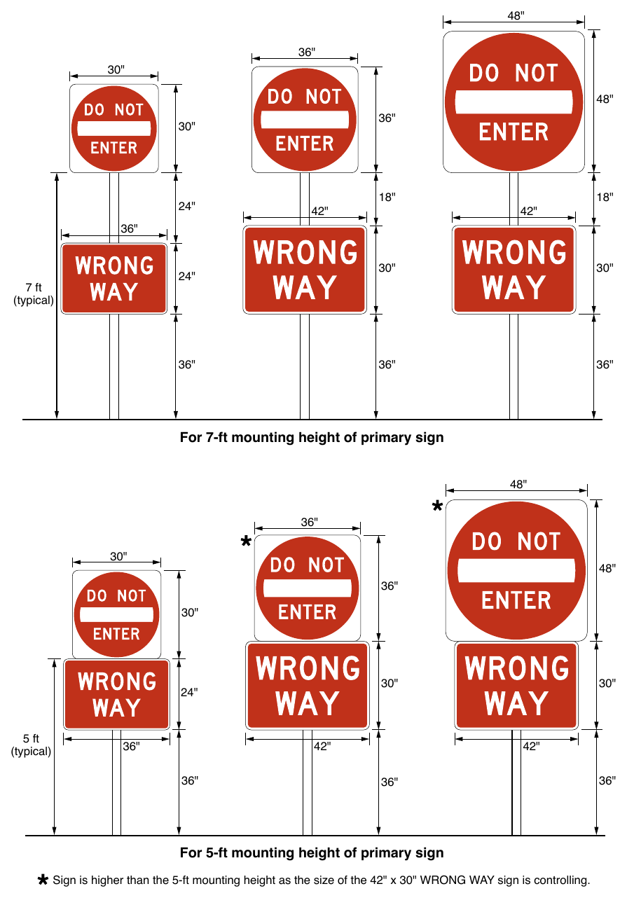
Sign is higher than the 5-ft mounting height as the size of the 42" x 30" WRONG WAY sign is controlling.
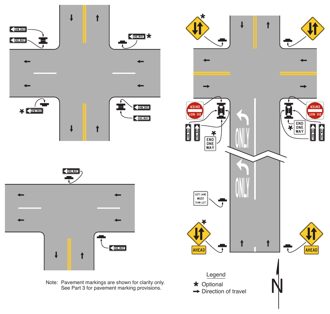
§2B.50 Divided Highway Crossing Signs (R6-3 and R6-3a)¶
Standard
01. On unsignalized minor-street approaches from which both left turns and right turns are permitted onto a divided highway at a crossing that functions as two separate intersections (see Section 2A.23), except as provided in Paragraph 2 of this Section, a Divided Highway Crossing (R6-3 or R6-3a) sign (see Figure 2B-13) shall be used to advise road users that they are approaching an intersection with a divided highway (see Figure 2B-19).
Option
02. If the divided highway has a traffic volume of less than 400 AADT and a speed limit of 25 mph or less, at a crossing that functions as two separate intersections, the Divided Highway Crossing signs facing the unsignalized minor-street approaches may be omitted.
03. A Divided Highway Crossing sign may be used on signalized minor-street approaches from which both left turns and right turns are permitted onto a divided highway to advise road users that they are approaching an intersection with a divided highway.
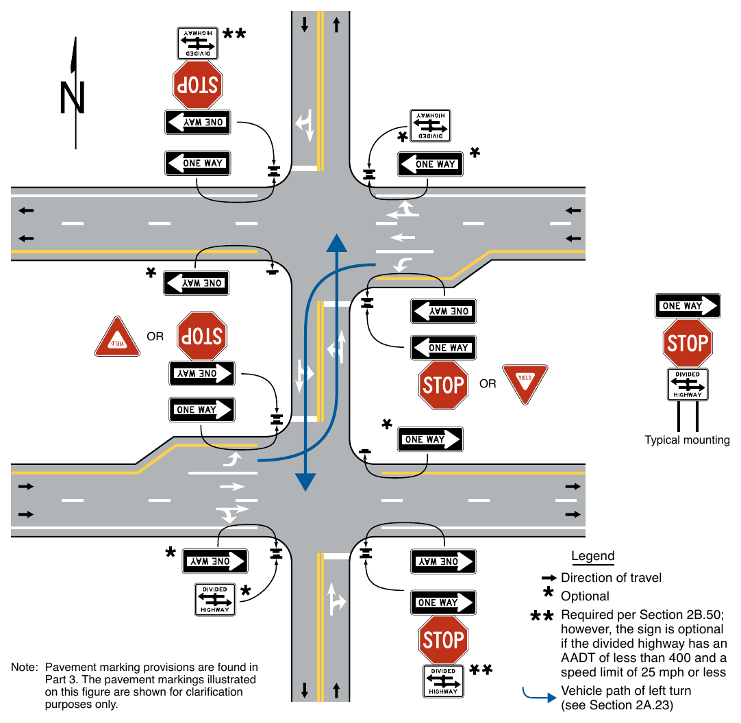
Note: Pavement marking provisions are found in Part 3. The pavement markings illustrated on this figure are shown for clarification purposes only. Direction of travel Optional Required per Section 2B.50; however, the sign is optional if the divided highway has an AADT of less than 400 and a speed limit of 25 mph or less Vehicle path of left turn (see Section 2A.23)
Standard
If a Divided Highway Crossing sign is used at a four-leg intersection, the R6-3 sign shall be used. If used at a T-intersection, the R6-3a sign shall be used.
05. The Divided Highway Crossing sign shall be located on the near right corner of the intersection, mounted beneath a STOP or YIELD sign or on a separate support.
Option
06. An additional Divided Highway Crossing sign may be installed on the left-hand side of the approach to supplement the Divided Highway Crossing sign on the near right corner of the intersection.
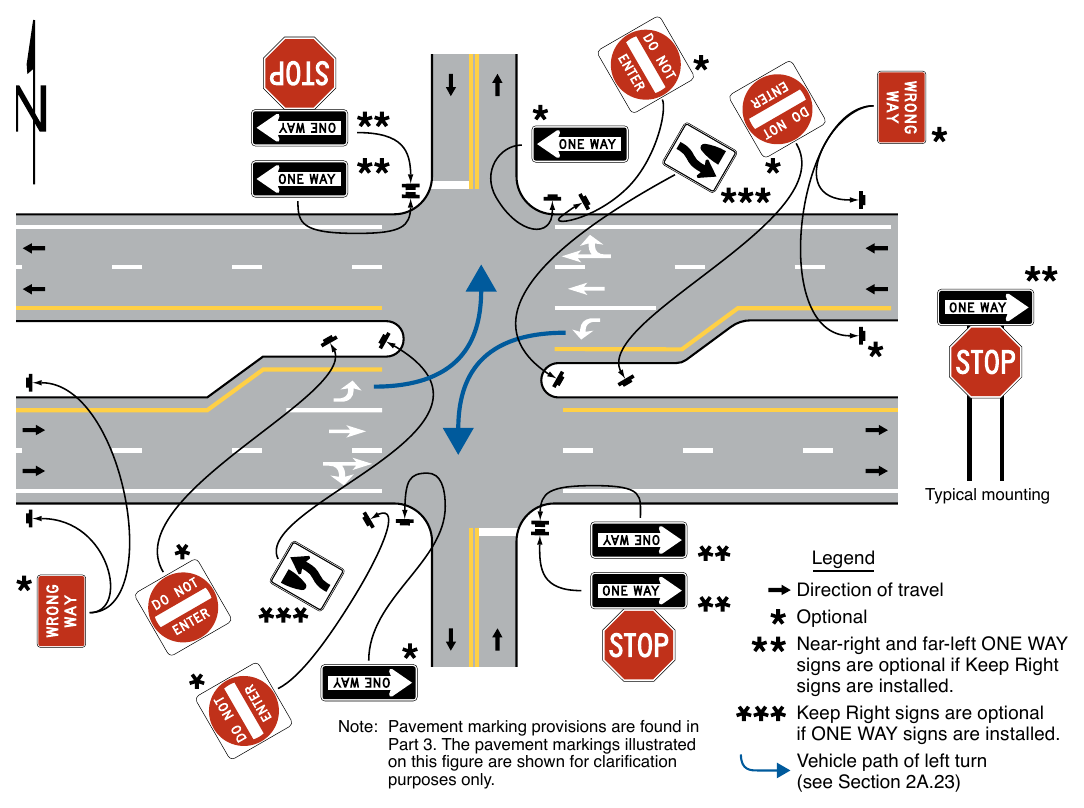
Signs shown: R6-5P
Note: Pavement marking provisions are found in Part 3. The pavement markings illustrated on this figure are shown for clarification purposes only. Direction of travel Optional Near-right and far-left ONE WAY signs are optional if Keep Right signs are installed. Keep Right signs are optional if ONE WAY signs are installed. Vehicle path of left turn (see Section 2A.23)
§2B.51 Roundabout Circulation Plaque (R6-5P)¶
Guidance
01. Where the central island of a roundabout or neighborhood traffic circle does not provide a reasonable place to install a sign as provided elsewhere in this Chapter, Roundabout Circulation (R6-5P) plaques (see Figure 2B-13) should be placed below the YIELD signs on each approach.
Support
02. Paragraph 6 of Section 2B.39 contains information about the use of a Keep Right (R4-7b) sign in the central island of a neighborhood traffic circle.
03. Paragraph 12 of Section 2B.49 contains information about the use of a ONE WAY (R6-1 or R6-2) sign in the central island of a roundabout.
Option
04. At roundabouts where ONE WAY signs have been installed in the central island, Roundabout Circulation plaques may be placed below the YIELD signs on approaches to roundabouts to supplement the central island signs.
05. The Roundabout Circulation plaque may be used at any type of circular intersection.
Support
06. Examples of regulatory and warning signs for roundabouts and neighborhood traffic circles are shown in Figures 2B-21 through 2B-24.
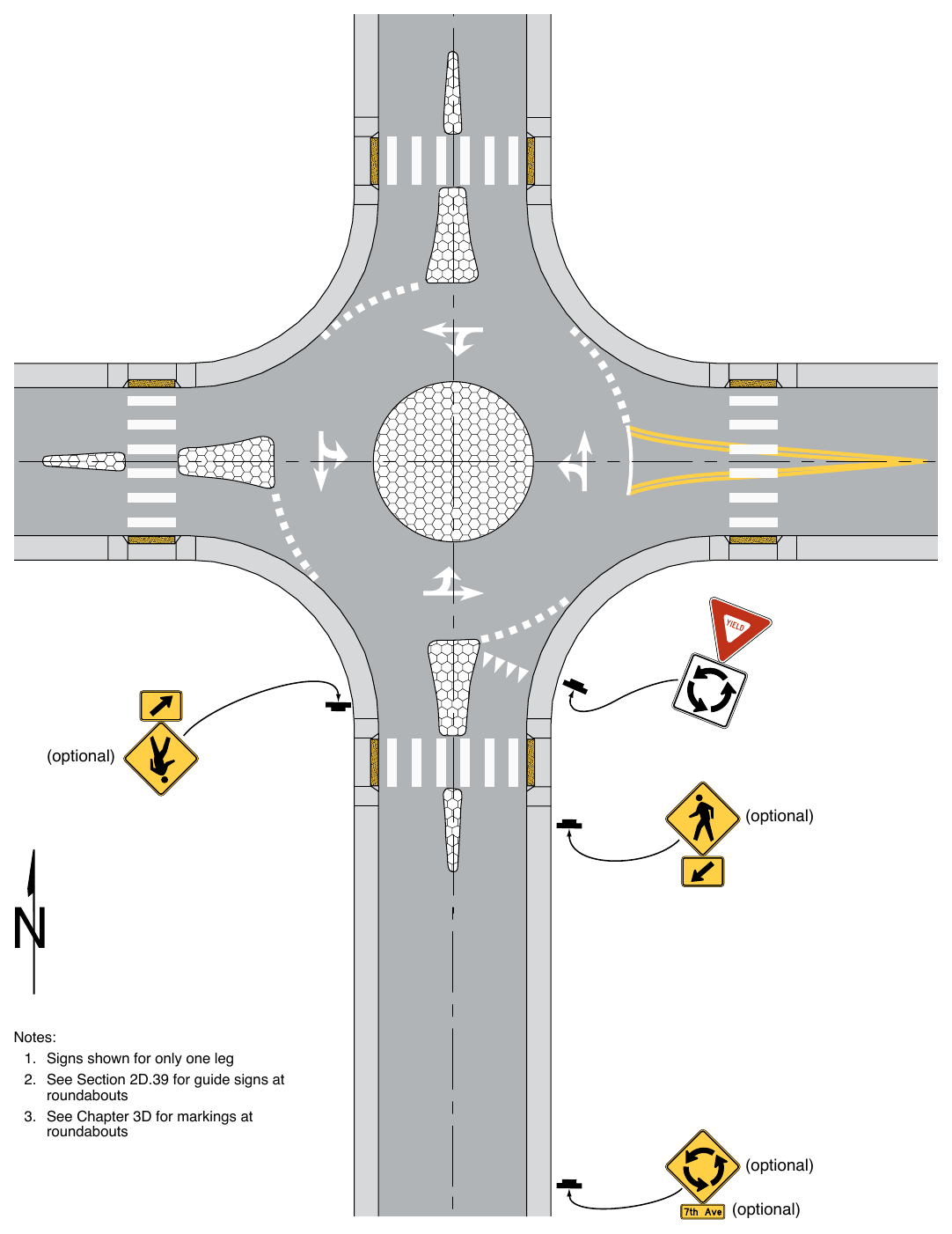
- 1. Signs shown for only one leg
- 2. See Section 2D.39 for guide signs at roundabouts
- 3. See Chapter 3D for markings at roundabouts (optional) (optional)
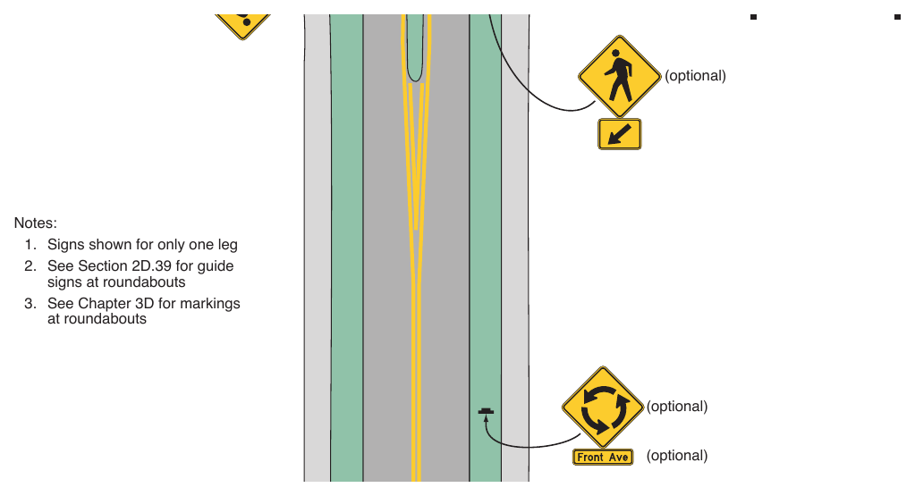
- 1. Signs shown for only one leg
- 2. See Section 2D.39 for guide signs at roundabouts
- 3. See Chapter 3D for markings at roundabouts (optional) (optional)
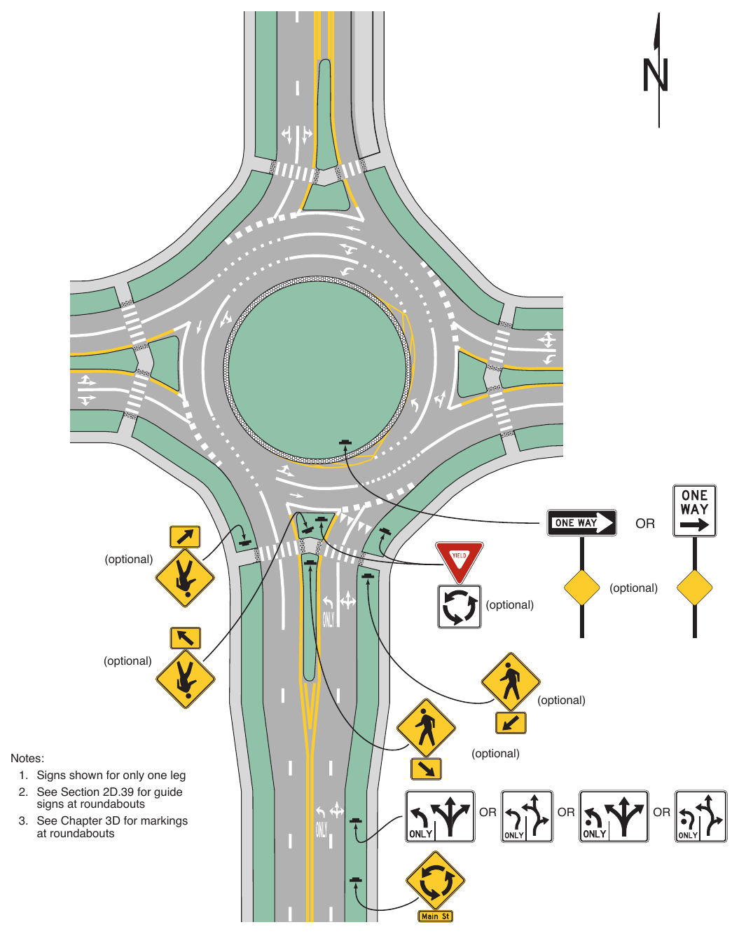
- 1. Signs shown for only one leg
- 2. See Section 2D.39 for guide signs at roundabouts
- 3. See Chapter 3D for markings at roundabouts (optional) OR OR OR
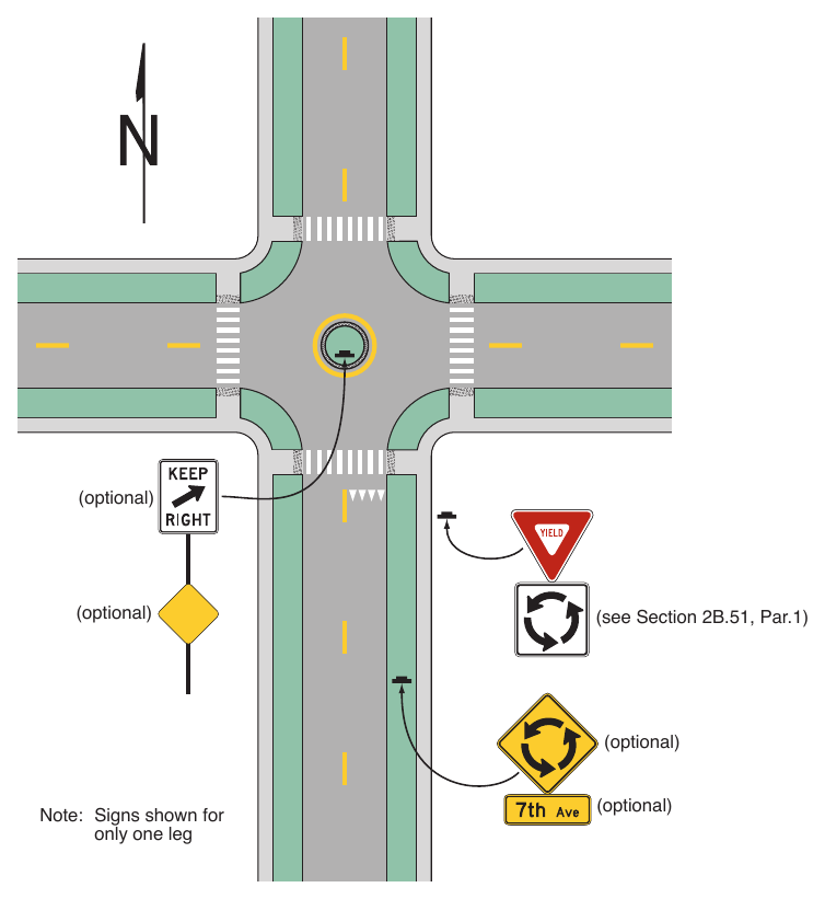
Note: Signs shown for only one leg (optional)
PARKING, STANDING, STOPPING, AND EMERGENCY RESTRICTION SIGNS¶
§2B.52 Parking, Standing, and Stopping Signs (R7 and R8 Series)¶
Support
01. Parking signs pertain to the parking, standing, and stopping of vehicles along the roadway and in designated parking areas. They cover a wide variety of regulations, and only general guidance can be provided here. The word “standing” when used on the R7 and R8 series of signs refers to the practice of a driver keeping the vehicle in a stationary position while continuing to occupy the vehicle. The word “stopping” when used on the R7 and R8 series signs refers to any vehicle, occupied by a driver or not, that stops other than to avoid conflict with other traffic or to comply with official direction. Other types of activities such as active loading, active passenger loading, and/or waiting might be established in State or local codes for use on R7 and R8 series signs.
02. Parking signs are categorized as either (1) prohibiting parking or (2) permitting parking with restrictions on how parking is allowed.
03. The types of parking, standing, or stopping prohibitions that might be encountered include, but are not limited to:
- A. Prohibited at all times;
- B. Prohibited only at certain times of the day and/or days of the week;
- C. Prohibited with exceptions, such as for bus stops, loading/unloading zones, persons with disabilities, or electric vehicle charging stations; or
- D. Prohibited under certain conditions, such as Snow Emergency Routes.
04. Permissive parking signs allowing parking with restrictions include, but are not limited to:
- A. Parking only allowed for limited time duration (such as 30 minutes or for 1 hour);
- B. Metered parking requiring payment at an individual or a multi-space parking meter, or through electronic means such as by telephone or mobile application;
- C. Parking only for specific persons (such as those with disabilities or patrons or employees of a business) or specific vehicle types (such as electric vehicles, police/government vehicles, motorcycles, bicycles, or taxis);
- D. Angled or back-in angled parking when it is not commonly used in the area;
- E. Parking programs such as neighborhood/residential permits, school areas, or special events; and
- F. Emergency parking or stopping only.
§2B.53 Design of Parking, Standing, and Stopping Signs¶
Standard
01. Parking, standing, or stopping signs (see Figure 2B-25) shall be rectangular or square.
02. Public agencies shall follow established law (State law, local ordinance, or regulation) as adopted by the authorized agency regarding what messages are allowed on parking signs.
03. The legend on parking signs shall state applicable regulations. Parking signs shall comply with the standards of shape, color, and location.
04. Prohibitive parking signs (see Drawing A in Figure 2B-25 for some commonly used examples) shall be used where parking is prohibited at all times or at specific times. Except as otherwise provided in this Section, parking signs shall have a red legend and border on a white background and, when the parking prohibition symbol is used, the symbol “P” shall be black.
05. Permissive parking signs (see Drawing B in Figure 2B-25) shall be used where only time-limited parking or parking in a particular manner is allowed. Permissive parking signs shall have a green legend and border on a white background.
Guidance
06. Parking information, should be displayed from top to bottom of the sign, as applicable, in the following order:
- A. The restriction or prohibition;
- B. The times of the day that it is applicable, if not all hours;
- C. The days of the week that it is applicable, if not every day;
- D. Qualifying or supplementary information;
- E. Exemptions to the restriction of prohibition; and
- F. Any tow-away message or symbol.
07. If the parking regulation applies to a limited area or zone, the limits of the regulation should be shown by arrows or supplemental plaques. If arrows are used and if the sign is at the end of a parking zone, there should be a single-headed arrow pointing in the direction that the regulation is in effect. If the sign is at an intermediate point in a zone, there should be a double-headed arrow pointing both ways. When a single sign is used at the transition point between two parking zones, it should display a right arrow and a left arrow pointing in the direction that the respective regulations apply.
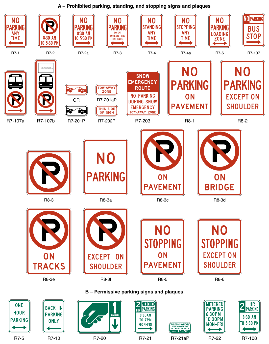
Signs shown: R7-1, R7-2, R7-2a, R7-3, R7-4, R7-4a, R7-6, R8-1, R8-2, R8-3, R8-3a, R8-3c, R8-3d, R8-3e, R8-3f, R8-5, R8-6, R7-5, R7-10, R7-20, R7-21, R7-21aP, R7-22
(R7 and R8 Series) (Sheet 1 of 2) A – Prohibited parking, standing, and stopping signs and plaques R7-2a R7-4a THIS AREA TO BE USED R7-107a R7-107b R7-201aP R8-3a R8-3c R8-3d R8-3e R8-3f B – Permissive parking signs and plaques R7-21aP
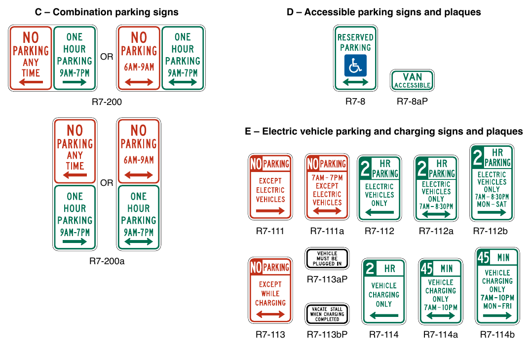
(R7 and R8 Series) (Sheet 2 of 2) C – Combination parking signs D – Accessible parking signs and plaques R7-8aP E – Electric vehicle parking and charging signs and plaques R7-111a R7-112a R7-114a R7-112b R7-200a R7-113aP R7-113bP R7-114b
Standard
08. The times and days for which the parking regulations are in effect shall be posted if they are not in effect at all times of day or all days of the week.
Option
09. As an alternate to the use of arrows to show designated restriction zones, the following word messages may be used: BEGIN, END, HERE TO CORNER, HERE TO ALLEY, and THIS SIDE OF SIGN.
10. The R8 series signs (see Drawing A in Figure 2B-25) may be used where sufficient notice of a parking prohibition is satisfied by the use of single signs and are not needed to designate the beginning and end of a zone in which parking is prohibited or restricted. In rural and certain other areas the legends NO PARKING ON PAVEMENT (R8-1) or NO STOPPING ON PAVEMENT (R8-5) are generally suitable and may be used where parking or stopping is allowed on an unpaved shoulder or border adjacent to the paved portion of the road. If a roadway has an adjacent paved shoulder on which parking or stopping is allowed, the legend NO PARKING EXCEPT ON SHOULDER (R8-2) or NO STOPPING EXCEPT ON SHOULDER (R8-6) may be used. The R8-3 symbol sign or the word message NO PARKING may be used to prohibit any parking along a roadway. Word legend supplemental plaques may be mounted below the NO PARKING signs or the word legend may be incorporated within signs whose sizes are increased accordingly. The R8-3 series signs may include word legends such as ON PAVEMENT (R8-3c), ON BRIDGE (R8-3d), ON TRACKS (R8-3e), and EXCEPT ON SHOULDERS (R8-3f).
Guidance
11. Where special parking restrictions are imposed during heavy snowfall or a declared snow emergency, a Snow Emergency Route (R7-203) sign (see Drawing A in Figure 2B-25) should be installed. The legend should be modified to display the specific regulations. The upper section of the sign should display the designation as a snow emergency route in a white legend and border on a red background.
12. If a fee is charged for on-street parking and payments are made at a multi-space parking meter, instead of individual parking meters for each parking space, Metered Parking (R7-21 and R7-22) signs (see Drawing B in Figure 2B-25) should be used to define the area where the multi-space parking meter applies. The Multi-Space Parking Meter (R7-20) sign (see Drawing B in Figure 2B-25) should be used at the meter location to direct road users to the meter.
Option
13. Where payments can be made electronically, such as by telephone or mobile application, the Mobile Parking Payment (R7-21aP) plaque (see Drawing B in Figure 2B-25) may be installed below or as part of the legend of a Metered Parking sign.
Standard
14. If the metered parking is subject to a maximum time limit, the appropriate time limit (number of hours or minutes) shall be displayed on the Metered Parking (R7-21 and R7-22) signs and, except as provided in Paragraph 15 of this Section, on the Multi-space Parking Meter (R7-20) signs.
Option
15. Where the maximum time limit varies by the time of the day or by the day of the week, the display of the time limits may be omitted from the R7-20 sign and, instead, be displayed on the multi-space parking meter so that they are visible to pedestrians as they make payments.
Standard
16. Where parking spaces are reserved for persons with disabilities, the Accessible Parking (R7-8) sign (see Drawing D in Figure 2B-25) shall be used to designate the space and shall display the official International Symbol of Accessibility.
17. Where parking spaces that are reserved for persons with disabilities are designed to accommodate wheelchair vans, a VAN ACCESSIBLE (R7-8aP) plaque (see Drawing D in Figure 2B-25) shall be mounted below the R7-8 sign.
Guidance
18. Where parking spaces are designated for parking of electric vehicles, an Electric Vehicle Parking (R7-111 series, R7-112 series, and R7-113) sign (see Drawing E of Figure 2B-25) should be installed adjacent to the designated spaces. Where there is no time limit, the R7-111 series sign should be used. Where parking is subject to a time limit, the R7-112 series sign should be used.
19. Where parking spaces are only designated for charging of electric vehicles, an R7-113 sign or R7-114 series sign (see Drawing E in Figure 2B-25) should be installed adjacent to the designated spaces.
20. Where additional restrictions apply while a vehicle occupies the designated space, the R7-113P series plaques should be installed below the R7-113 sign or the R7-114 series signs.
Option
21. Where parking is prohibited during certain hours and time-limited parking or parking in a particular manner is allowed during certain other time periods, the red Parking Prohibition and green Permissive Parking signs may be designed as follows (see Drawing C in Figure 2B-25):
- A. Two 12 x 18-inch parking signs may be used with the red Parking Prohibition (R7-1) sign installed above or to the left of the green Permissive Parking (R7-108) sign; or
- B. A single sign (R7-200 or R7-200a) may be used.
22. At the transition point between two parking zones, a single sign (R7-200 or R7-200a) or two signs mounted side-by-side may be used.
23. The words NO PARKING may be used as an alternative to the No Parking symbol (see the R7-2a sign in Drawing A in Figure 2B-25).
24. Alternate designs for the R7-107 sign may be developed such as the R7-107a sign (see Drawing A in Figure 2B-25). Alternate designs may include, on a single sign, a transit logo, an approved bus symbol, a parking prohibition, the words BUS STOP, and an arrow. The reverse side of the R7-107 series signs may display bus routing information for pedestrians.
25. A Tow-Away Zone (R7-201P or R7-201aP) plaque (see Drawing A in Figure 2B-25) may be mounted below any parking prohibition sign. The word legend TOW-AWAY ZONE may be incorporated into the parking prohibition sign in lieu of using a separate plaque.
26. The R7-201P plaque may have a black or red symbol and border on a white background.
Guidance
27. When a legend other than that on the standard parking signs is necessary, letter height, symbol size, and basic sign layout should be consistent with those shown on the standard parking signs as detailed in the “Standard Highway Signs” publication (see Section 1A.05).
28. In general, the letter height of the principal legend on parking signs sized for urbanized applications should be at least 2 inches.
§2B.54 Placement of Parking, Standing, and Stopping Signs¶
Support
01. The efficacy of parking, standing, and stopping signs, when used on conventional roads in urbanized or developed environments, depends on their visibility and consistent placement along a street or within a particular block. It is often impracticable for the entire legend to be legible from similar distances as for other types of signs. Therefore, it is important that their conventional form be recognizable from an adequate distance such that the road user can obtain the information upon closer inspection.
Guidance
02. When signs with arrows are used to indicate the extent of the restricted zones, the signs should be set at an angle of not less than 30 degrees or more than 45 degrees with the line of traffic flow in order to be visible to approaching traffic.
03. When signs are placed at the head of perpendicular parking stalls, the signs should be parallel to the roadway facing the parking stall.
04. Spacing of signs should be based on legibility, conspicuity, and sign orientation.
05. If the zone is long, signs should be used at intermediate points within the zone.
06. If the signs are mounted at an angle of 90 degrees to the curb line, two signs should be mounted back to back at the transition point between two parking zones, each with an appended THIS SIDE OF SIGN (R7-202P) supplemental plaque (see Drawing A in Figure 2B-25).
07. If the signs are mounted at an angle of 90 degrees to the curb line, signs without any arrows or appended plaques should be used at intermediate points within a parking zone, facing in the direction of approaching traffic. Otherwise, the standards of placement should be the same as for signs using directional arrows.
Option
08. Blanket parking regulations that apply to an entire jurisdiction may, if legal, be posted in the vicinity of the jurisdictional boundary lines. Blanket parking regulations that apply to a posted zone or district may, if legal, be posted at the entry points to the zone or district.
§2B.55 Emergency Restriction Signs (R8-4 and R8-7)¶
Standard
01. Emergency Restriction signs (see Figure 2B-26) shall be rectangular and shall have a black legend and border on a white background.
Option
02. The EMERGENCY PARKING ONLY (R8-4) sign or the EMERGENCY STOPPING ONLY (R8-7) sign may be used to discourage or prohibit shoulder parking, particularly where scenic or other attractions create a tendency for road users to desire to stop temporarily.
Support
03. Section 8B.07 contains information for the use of the DO NOT STOP ON TRACKS (R8-8) sign (see Figure 8B-1) to discourage or prohibit parking or stopping on railroad or light rail transit tracks.
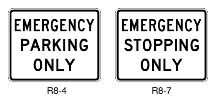
PEDESTRIAN SIGNS¶
§2B.56 WALK ON LEFT FACING TRAFFIC and No Hitchhiking Signs (R9-1, R9-4, and R9-4a)¶
Option
01. The WALK ON LEFT FACING TRAFFIC (R9-1) sign (see Figure 2B-27) may be used on highways where no sidewalks are provided.
Guidance
02. If used, the WALK ON LEFT FACING TRAFFIC sign should be installed on the right-hand side of the road where pedestrians walk on the pavement or shoulder in the absence of pedestrian pathways or sidewalks.
Option
03. The No Hitchhiking (R9-4) sign (see Figure 2B-27) may be used to prohibit standing in or adjacent to the roadway for the purpose of soliciting a ride. The R9-4a word message sign (see Figure 2B-27) may be used as an alternate to the R9-4 symbol sign.
§2B.57 Pedestrian Crossing Signs (R9-2 and R9-3)¶
Option
01. Pedestrian Crossing signs (see Figure 2B-27) may be used to limit pedestrian crossing to specific locations.
Standard
02. If used, Pedestrian Crossing signs shall be installed to face pedestrian approaches.
Option
03. Where crosswalks are clearly defined, the CROSS ONLY AT CROSSWALKS (R9-2) sign may be used to prohibit pedestrians from crossing at locations away from crosswalks.
04. The No Pedestrian Crossing (R9-3) sign may be used to prohibit pedestrians from crossing a roadway at an undesirable location or in front of a school or other public building where a crossing is not designated.
05. The NO PEDESTRIAN CROSSING (R9-3a) word message sign may be used as an alternate to the R9-3 symbol sign. The USE CROSSWALK (R9-3bP) supplemental plaque, along with an arrow, may be installed below either sign to designate the direction of the crossing.
Support
06. Pedestrians with vision disabilities might need features other than traffic control devices to provide effective communication of the prohibition of pedestrian crossing.
Guidance
07. The R9-3bP plaque should not be installed in combination with educational plaques.
§2B.58 Traffic Signal Pedestrian and Bicyclist Actuation Signs (R10-1 through R10-4 and R10-24 through R10-26)¶
Standard
01. Where manual actuation of a traffic signal is required for pedestrians or bicyclists to call a signal phase to cross the roadway, traffic signal signs applicable to pedestrian actuation (see Figure 2B-27) or bicyclist actuation (see Figure 9B-1) shall be mounted immediately above or incorporated into the push button detector units (see Section 4I.05).
Support
02. Traffic signal signs applicable to pedestrians include:
- A. CROSS ONLY ON GREEN (symbolic circular green) (R10-1),
- B. CROSS ONLY ON (symbolic walk indication) SIGNAL (R10-2),
- C. Push Button for Walk Signal (R10-3 series), and
- D. Push Button for Green Signal (R10-4 series).
Option
03. The following signs may be used as an alternate for the R10-3 and R10-4 signs:
- A. Push Button to Cross Street Wait for Walk Signal (R10-3a); or
- B. Push Button to Cross Street Wait for Green Signal (R10-4a).
04. The name of the street to be crossed may be substituted for the word STREET in the legends on the R10-3a and R10-4a signs.
Guidance
05. The finger in the push button symbol on the R10-3, R10-3a, R10-4, and R10-4a signs should point in the same direction as the arrow on the sign.
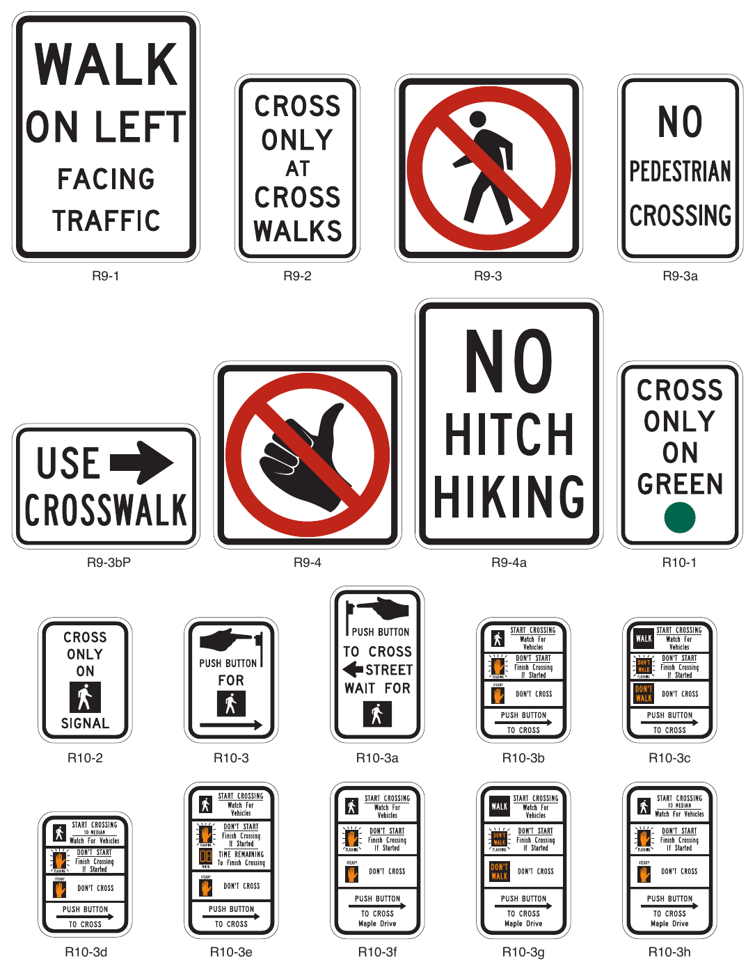
Signs shown: R9-1, R9-2, R9-3, R9-3a, R9-3bP, R9-4, R9-4a, R10-1, R10-2, R10-3, R10-3a, R10-3b, R10-3c, R10-3d, R10-3e, R10-3f, R10-3g, R10-3h
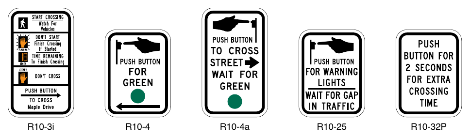
Signs shown: R10-3i, R10-4, R10-4a, R10-25, R10-32P, R10-3b, R10-3, R10-3c, R10-3d, R10-3e
Option
06. Where symbolic pedestrian signal indications are used, an educational sign (R10-3b) may be used instead of the R10-3 sign to improve pedestrian understanding of pedestrian indications at signalized intersections. Where word-legend pedestrian signal indications are being retained for the remainder of their useful service life, the legends WALK/DONT WALK may be substituted for the symbols on the educational sign R10-3b, thus creating educational sign R10-3c. The R10-3d educational sign may be used to inform pedestrians that the pedestrian clearance time is sufficient only for the pedestrian to cross to the median at locations where pedestrians cross in two stages using a median refuge island. The R10-3e educational sign may be used where countdown pedestrian signals have been provided. In order to assist the pedestrian in understanding which push button to push, the R10-3f through R10-3i educational signs that provide the name of the street to be crossed may be used instead of the R10-3b through R10-3e educational signs.
07. The R10-24 or R10-26 sign (see Section 9B.20) may be used where a push button detector has been installed exclusively to actuate a green phase for bicyclists.
08. The R10-25 sign (see Figure 2B-27) may be used where a push button detector has been installed for pedestrians to activate In-Roadway Warning Lights (see Chapter 4U) or flashing beacons that have been added to the pedestrian warning signs.
Support
09. Section 4I.05 contains information regarding the application of the R10-32P plaque.
TRAFFIC SIGNAL SIGNS AND PLAQUES¶
§2B.59 Traffic Signal Signs and Plaques (R10-5 through R10-30)¶
Option
01. To supplement traffic signal control, traffic signal (R10-5 through R10-30) signs (see Figure 2B-28) may be used to regulate road users.
02. Traffic signal signs may be installed at certain locations to clarify signal control. Among the legends that may be used for this purpose are:
- A. LEFT (RIGHT) ON GREEN ARROW ONLY (R10-5),
- B. STOP HERE ON RED (R10-6 or R10-6a) for observance of stop lines,
- C. DO NOT BLOCK INTERSECTION (R10-7) for avoidance of traffic obstructions,
- D. USE LANE(S) WITH GREEN ARROW (R10-8) for obedience to lane-use control signals (see Chapter 4T),
- E. LEFT (RIGHT) TURN SIGNAL (R10-10),
- F. U TURN SIGNAL (R10-10a) for exclusive control of a U-turn movement,
- G. U TURN YIELD TO RIGHT TURN (R10-16),
- H. LEFT (RIGHT) TURN YIELD ON GREEN (symbolic circular green) (R10-12),
- I. LEFT (RIGHT) TURN YIELD ON FLASHING YELLOW ARROW (R10-12a), and
- J. LEFT (RIGHT) TURN YIELD ON FLASHING RED ARROW AFTER STOP (R10-27).
Guidance
03. If used, the LEFT ON GREEN ARROW ONLY sign, the LEFT TURN SIGNAL sign, the LEFT TURN YIELD ON GREEN (symbolic circular green) sign, the LEFT TURN YIELD ON FLASHING YELLOW ARROW sign, or the LEFT TURN YIELD ON FLASHING RED ARROW AFTER STOP sign should be located adjacent to the left-turn signal face.
04. If used, the RIGHT ON GREEN ARROW ONLY sign, the RIGHT TURN SIGNAL sign, the RIGHT TURN YIELD ON FLASHING YELLOW ARROW sign, or the RIGHT TURN YIELD ON FLASHING RED ARROW AFTER STOP sign should be located adjacent to the right-turn signal face.
05. A U TURN YIELD TO RIGHT TURN (R10-16) sign should be installed near the left-turn signal face if U-turns are allowed on a protected left-turn movement on an approach from which a right-turn GREEN ARROW signal indication is simultaneously being displayed to drivers making a right turn from the conflicting approach to their left.
Option
06. If used, a U TURN SIGNAL (R10-10a) sign may be installed adjacent to the signal face that exclusively controls a U-turn movement.
07. If needed for additional emphasis, an additional LEFT TURN YIELD ON GREEN (symbolic circular green) (R10-12) sign with an AT SIGNAL (R10-31P) supplemental plaque (see Figure 2B-28) may be installed in advance of the intersection.
08. In situations where traffic control signals are coordinated for progressive timing, the Traffic Signal Speed (I1-1) sign may be used (see Section 2H.04).
Standard
09. The CROSSWALK—STOP ON RED (symbolic circular red) (R10-23) and STOP ON RED—YIELD ON FLASHING RED AFTER STOP (R10-23a) signs (see Figure 2B-28) shall only be used in conjunction with pedestrian hybrid beacons (see Section 4J.02).
10. The EMERGENCY SIGNAL (R10-13) sign (see Figure 2B-28) shall be used in conjunction with emergency-vehicle traffic control signals (see Section 4M.02).
11. The EMERGENCY SIGNAL—STOP ON FLASHING RED (R10-14 or R10-14a) sign (see Figure 2B-28) shall be used in conjunction with emergency-vehicle hybrid beacons (see Section 4N.02).
Option
12. If needed for extra emphasis, a STOP HERE ON FLASHING RED (R10-14b) sign may be installed with an emergency-vehicle hybrid beacon.
Standard
13. The Left Turn Yield to Bicycles (R10-12b) sign shall be limited to applications where the conflicting bicyclist movement would be unexpected in direction, location, or similar condition that would tend to violate the expectation of a turning motorist.
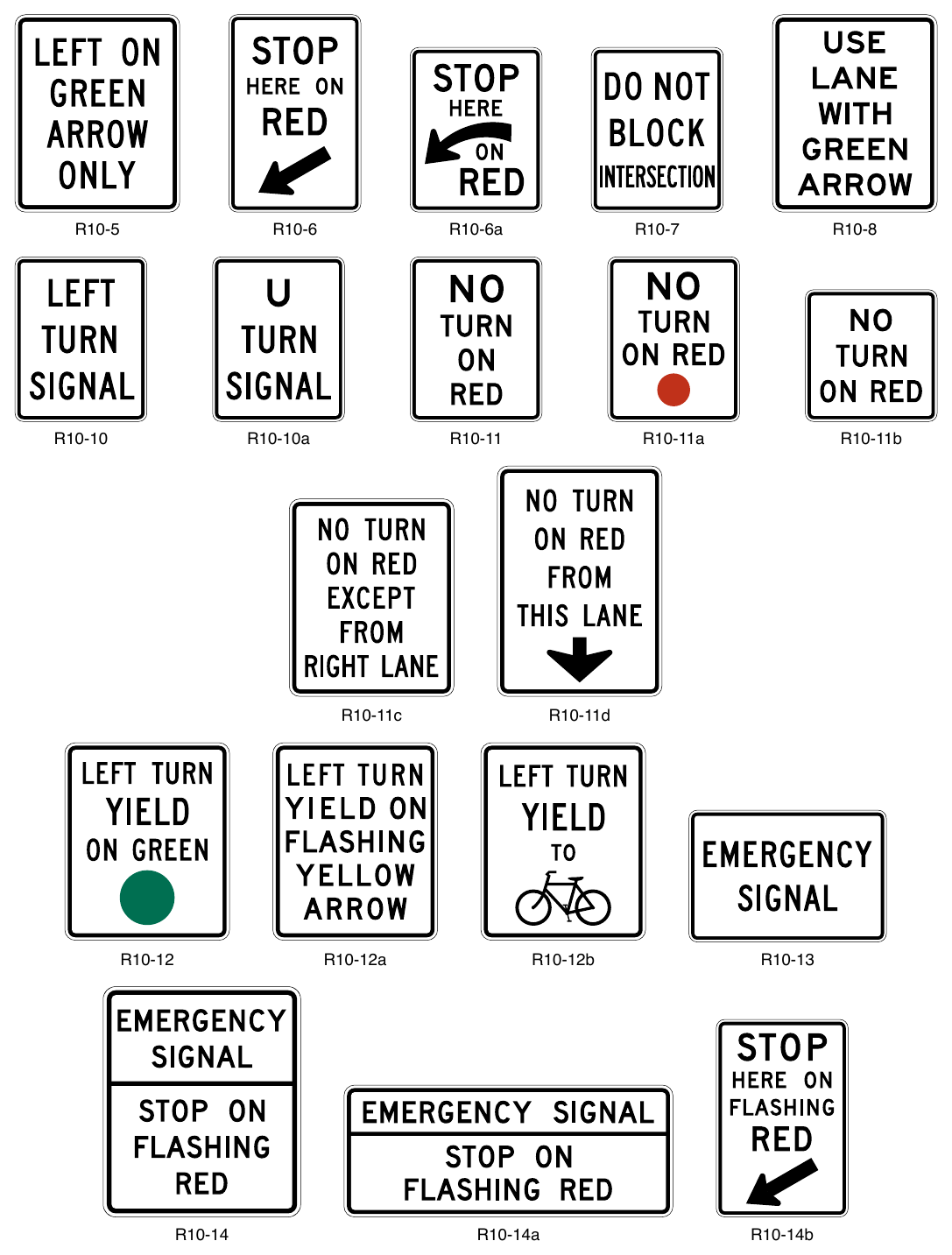
Signs shown: R10-5, R10-6, R10-6a, R10-7, R10-8, R10-10, R10-10a, R10-11, R10-11a, R10-11b, R10-11c, R10-11d, R10-12, R10-12a, R10-12b, R10-13, R10-14, R10-14a, R10-14b
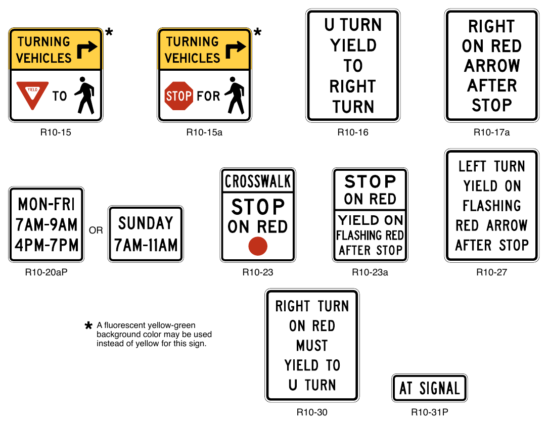
Signs shown: R10-15, R10-15a, R10-16, R10-17a, R10-20aP, R10-23, R10-23a, R10-27, R10-30, R10-31P
instead of yellow for this sign.
Guidance
14. The Left Turn Yield to Bicycles sign should be located adjacent to the left-turn signal face.
Option
15. If needed for additional emphasis, an additional Left Turn Yield to Bicycles sign with an AT SIGNAL (R10-31P) supplemental plaque (see Figure 2B-28) may be installed in advance of the intersection for motor vehicles.
16. Where conditions might warrant additional emphasis to drivers turning at a signalized intersection where potential pedestrian conflicts might not be readily apparent, a Turning Vehicles Yield to (Stop for) Pedestrians (R10-15, R10-15a) sign (see Figure 2B-28) may be used.
Standard
17. The Turning Vehicles Stop for Pedestrians (R10-15a) sign shall only be used in jurisdictions where laws, ordinances or resolutions specifically require that a driver must stop for a pedestrian.
Guidance
18. The R10-15 series signs, where used, should be placed as follows:
- A. On the near right corner of the signalized intersection for right-turning vehicles.
- B. On the far left corner of the signalized intersection for the left-turning vehicles onto a two-way street.
- C. On the near left corner of the signalized intersection for left-turning vehicles from a one-way street onto a one-way street.
§2B.60 No Turn on Red Signs (R10-11 Series, R10-17a, and R10-30)¶
Standard
01. Where a right turn on a circular red signal indication (or a left turn on a circular red signal indication from a one-way street to a one-way street) is to be prohibited, a NO TURN ON RED (R10-11, R10-11b) word message sign (see Figure 2B-28) shall be used. A NO TURN ON RED (symbolic circular red) (R10-11a) sign (see Figure 2B-28) shall be used when the approach is controlled by both circular red and red arrow indications.
Guidance
02. If used, the No Turn on Red sign should be installed near the appropriate signal head.
03. A No Turn on Red sign should be considered when an engineering study finds that one or more of the following conditions exists:
- A. Inadequate sight distance to vehicles approaching from the left (or right, if applicable);
- B. Geometrics or operational characteristics of the intersection that might result in unexpected conflicts;
- C. An exclusive pedestrian or bicycle phase;
- D. An unacceptable number of conflicting pedestrian movements with right-turn-on-red maneuvers, especially involving children, older pedestrians, or persons with disabilities;
- E. More than three right-turn-on-red crashes reported in a 12-month period for the particular approach; or
- F. The skew angle of the intersecting roadways creates difficulty for drivers to see traffic approaching from their left (or right, if applicable).
Standard
04. If an R10-11, R10-11a, R10-11b, or R10-17a sign with conventional road size as shown in Table 2B-1 is used on an approach on the far side of the intersection and the distance between the stop line and the sign is greater than 120 feet, then a duplicate sign shall be located on the near side of the intersection to supplement the sign on the far side of the intersection.
Option
05. When a no-turn-on-red restriction applies during certain time periods only, the following alternatives may be used:
- A. Movement Prohibition (R3-1, R3-2, R3-4, R3-18, and R3-27) signs or NO TURN ON RED signs displayed by using a blank-out sign for the time period or one or more portion(s) of a particular cycle of the traffic control signal during which the prohibition is applicable; or
- B. Static signs incorporating a supplemental legend or with a supplemental R10-20aP plaque (see Figure 2B28) showing the hours and days during which the prohibition is applicable.
06. White LEDs may be used in the border and activated during periods of turn prohibition to enhance the sign conspicuity.
07. On signalized approaches with more than one right-turn lane, a NO TURN ON RED EXCEPT FROM RIGHT LANE (R10-11c) sign (see Figure 2B-28) may be post-mounted at the intersection or a NO TURN ON RED FROM THIS LANE (with down arrow) (R10-11d) sign (see Figure 2B-28) may be mounted over the approximate center of the lane from which turns on red are prohibited.
Guidance
08. Where turns on red are permitted and the signal indication is a steady RED ARROW, the RIGHT (LEFT) ON RED ARROW AFTER STOP (R10-17a) sign (see Figure 2B-28) should be installed adjacent to the RED ARROW signal indication.
Option
09. A RIGHT TURN ON RED MUST YIELD TO U-TURN (R10-30) sign (see Figure 2B-28) may be installed to remind road users that they must yield to conflicting U-turn traffic on the street or highway onto which they are turning right on a red signal after stopping.
§2B.61 Ramp Metering Signs (R10-28 and R10-29)¶
Option
01. When ramp control signals (see Chapter 4P) are used to meter traffic on a freeway or expressway entrance ramp, regulatory signs with legends appropriate to the control may be installed adjacent to the ramp control signal faces.
02. For entrance ramps with only one controlled lane, an XX VEHICLE(S) PER GREEN (R10-28) sign (see Figure 2B-29) may be used to inform road users of the number of vehicles that are permitted to proceed during each short display of the green signal indication. For entrance ramps with more than one controlled lane, an XX VEHICLE(S) PER GREEN EACH LANE (R10-29) (see Figure 2B-29) sign may be used to inform road users of the number of vehicles that are permitted to proceed from each lane during each short display of the green signal indication.
Support
03. Chapter 2L contains provisions for the use of blank-out or changeable message signs when the metering is limited by time, day, or condition.
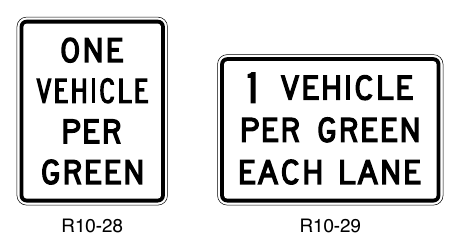
ROAD CLOSED AND WEIGHT LIMIT SIGNS¶
§2B.62 KEEP OFF MEDIAN Sign (R11-1)¶
Option
01. The KEEP OFF MEDIAN (R11-1) sign (see Figure 2B-30) may be used to prohibit driving into or parking on the median.
Guidance
02. The KEEP OFF MEDIAN sign should be installed on the left-hand side of the roadway within the median at random intervals as needed wherever there is a tendency for encroachment.
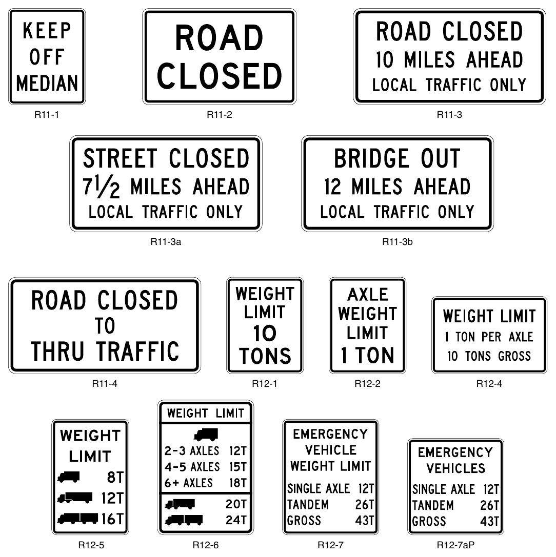
Signs shown: R11-1, R11-2, R11-3, R11-3a, R11-3b, R11-4, R12-1, R12-2, R12-4, R12-5, R12-6, R12-7, R12-7aP
§2B.63 ROAD CLOSED Sign (R11-2) and LOCAL TRAFFIC ONLY Signs¶
Guidance
01. The ROAD CLOSED (R11-2) sign should be installed where roads have been closed to all traffic (except authorized vehicles).
02. ROAD CLOSED—LOCAL TRAFFIC ONLY (R11-3) or ROAD CLOSED TO THRU TRAFFIC (R11-4) signs should be used where through traffic is not permitted, or for a closure some distance beyond the sign, but where the highway is open for local traffic up to the point of closure.
Standard
03. The Road Closed (R11-2, R11-3 series, and R11-4) signs (see Figure 2B-30) shall be designed as horizontal rectangles. These signs shall be preceded by the applicable Advance Road Closed warning sign with the secondary legend AHEAD and, if applicable, an Advance Detour warning sign (see Section 6H.04).
Option
04. An intersecting street name or a well-known destination may be substituted for the XX MILES AHEAD legend in urban areas.
05. The word message BRIDGE OUT may be substituted for the ROAD CLOSED legend where applicable.
06. Where conditions allow for bicycle travel on the road beyond the point of closure to motor vehicles, an EXCEPT BICYCLES (R3-7bP) plaque (see Figure 2B-4) may be used with the ROAD CLOSED sign.
§2B.64 Weight Limit Signs (R12-1 through R12-7)¶
Standard
01. Weight limit signs (see Figure 2B-30) shall be used to indicate a section of highway or structure that has a vehicle weight restriction.
Guidance
02. The units shown on any weight limit sign should be consistent within a State or region with respect to pounds or tons.
Option
03. Where the restriction applies to axle weight rather than gross load, the legend AXLE WEIGHT LIMIT XX TONS or AXLE WEIGHT LIMIT XX LBS (R12-2) may be used.
04. In areas where multiple regulations are applicable, such as limiting both axle weight and gross vehicle weight, a WEIGHT LIMIT XX TONS PER AXLE, XX TONS GROSS (R12-4) sign combining the necessary messages on a single sign may be used.
05. Posting of specific load limits may be accomplished by use of the Weight Limit (R12-5) symbol sign. A sign containing the legend WEIGHT LIMIT on the top two lines, and showing up to three different truck symbols and their respective weight limits for which restrictions apply may be used, with the weight limits displayed to the right of each symbol as XX T. A bottom line of legend stating GROSS WT may be included if needed for enforcement purposes.
Support
06. A specialized hauling vehicle is a single unit truck with multiple closely-spaced axles. Examples include dump trucks, construction vehicles, solid waste trucks and other hauling trucks. Specialized hauling vehicles typically have 4 to 7 axles.
Option
07. The Weight Limit (R12-6) sign may be used to indicate vehicle weight restrictions for specialized hauling vehicles.
Standard
08. The symbols shown on the R12-5 and R12-6 Weight Limit sign shall apply to all trucks of that configuration (single-unit, single-trailer or multi-trailer) regardless of the shape of the vehicle. Symbolic representations of other vehicle shapes or modifications of standard symbols shall not be used.
Option
09. The facility type (such as “BRIDGE”) may be added to the legend of the sign to clarify the specific applicability of the weight limit.
Standard
10. If the R12-5 sign depicts only one single-unit vehicle symbol, the weight limit associated with that singleunit vehicle symbol shall apply to all single-unit vehicles, regardless of number of axles.
11. The weight limit associated with the single-trailer vehicle symbol shall apply to all single-trailer vehicles, regardless of number of axles or vehicle shape.
12. The weight limit associated with the multi-trailer vehicle symbol shall apply to all multi-trailer vehicles with two or more trailers, regardless of number of axles or vehicle shape.
13. A weight limit sign (see Figure 2B-30) shall be located at the applicable section of highway or structure.
14. An additional weight limit sign, with an advisory distance or directional legend, shall be located in advance of the applicable section of highway or structure so that prohibited vehicles can detour or turn around prior to the limit zone.
Support
15. An emergency vehicle is designed to be used under emergency conditions to transport personnel and equipment to support the suppression of fires and mitigation of other hazardous situations. Emergency vehicles are typically operated by fire departments and are primarily equipped for firefighting, but are also used to respond to and mitigate other hazardous situations in an emergency. They can create higher load effects compared to nonemergency vehicles of similar weight.
Option
16. The Emergency Vehicle Weight Limit (R12-7) sign carrying the legend EMERGENCY VEHICLE WEIGHT LIMIT SINGLE AXLE XX TONS, TANDEM XX TONS, and GROSS XX TONS may be used to indicate vehicle weight restrictions for emergency vehicles.
Standard
17. When the emergency-vehicle weight limit is displayed in the same assembly as the primary weight limit sign, the Emergency Vehicle Weight Limit (R12-7aP) plaque shall be mounted below.
§2B.65 Weigh Station Sign (R13-1)¶
Guidance
01. An R13-1 sign with the legend TRUCKS OVER XX TONS MUST ENTER WEIGH STATION NEXT RIGHT (see Figure 2B-31) should be used to direct appropriate traffic into an inspection station.
02. The R13-1 sign should be supplemented by the D8 series of guide signs (see Section 2D.51).
§2B.66 TRUCK ROUTE Sign (R14-1)¶
Guidance
01. The TRUCK ROUTE (R14-1) sign (see Figure 2B-31) should be used to mark a route that has been designated to allow truck traffic.
Support
02. Section 2D.20 contains information regarding the use of the TRUCK (M4-4P) auxiliary plaque (see Figure 2D-5) on a designated numbered alternative route.
§2B.67 Hazardous Material Signs (R14-2 and R14-3)¶
Option
01. The Hazardous Material Route (R14-2) sign (see Figure 2B-31) may be used to identify routes that have been designated by proper authority for vehicles transporting hazardous material.
02. On routes where the transporting of hazardous material is prohibited, the Hazardous Material Prohibition (R14-3) sign (see Figure 2B-31) may be used.
Guidance
03. If used, the Hazardous Material Prohibition sign should be installed on a street or roadway at a point where vehicles transporting hazardous material have the opportunity to take an alternate route.
§2B.68 National Network Signs (R14-4 and R14-5)¶
Support
01. The signing of the National Network routes for trucking is optional.
Standard
02. When a National Network route is signed, the National Network (R14-4) sign (see Figure 2B-31) shall be used.
Option
03. The National Network Prohibition (R14-5) sign (see Figure 2B-31) may be used to identify routes, portions of routes, and ramps where trucks are prohibited. The R14-5 sign may also be used to mark the ends of designated routes.
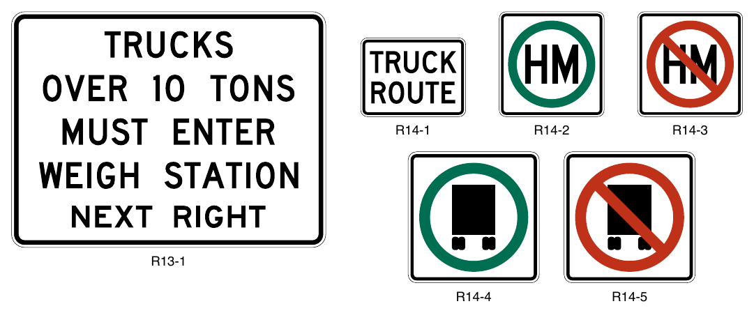
OTHER REGULATORY SIGNS AND PLAQUES¶
§2B.69 Photo Enforced Signs and Plaques (R10-18, R10-18a, R10-19P, R10-19aP)¶
Option
01. A Traffic Laws Photo Enforced (R10-18) sign (see Figure 2B-32) may be installed at a jurisdictional boundary to advise road users that some of the traffic regulations within that jurisdiction are being enforced by photographic equipment.
02. A Traffic Signal Photo Enforced (R10-18a) sign (see Figure 2B-32) may be installed in advance of or at a traffic signal to advise road users that compliance with the signal is enforced by photographic equipment. A Signal Ahead (W3-3) sign and a Traffic Signal Photo Enforced (R10-18a) sign may be used on the same approach provided that they are on separate supports.
03. A Photo Enforced (R10-19P) plaque or a PHOTO ENFORCED (R10-19aP) word message plaque (see Figure 2B-32) may be mounted below a regulatory sign to advise road users that the regulation is being enforced by photographic equipment.
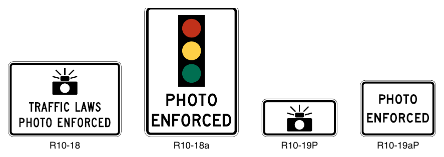
Signs shown: R10-18, R10-18a, R10-19P, R10-19aP, W3-3, R16-4
Standard
04. The Traffic Signal Photo Enforced (R10-18a) sign shall not be installed on approaches to signalized locations where red-light cameras are not present on any of the approaches to the signalized location.
05. A Traffic Signal Photo Enforced (R10-18a) sign shall not be installed on the same support in combination with a Signal Ahead (W3-3) sign.
06. If used below a regulatory sign, the Photo Enforced (R10-19P or R10-19aP) plaque shall be a rectangle with a black legend and border on a white background.
§2B.70 Move Vehicles from Travel Lanes Sign (R16-4)¶
Option
01. A STATE LAW MINOR CRASHES MOVE VEHICLES FROM TRAVEL LANES (R16-4) sign (see Figure 2B-33) may be installed in accordance with the provisions of Section 2A.01 to require motorists to move their vehicle out of the travel lanes if they have been involved in a crash.
02. If the specific requirements of a State law vary, the word legend of the R16-4 sign may be modified to reflect the appropriate law.
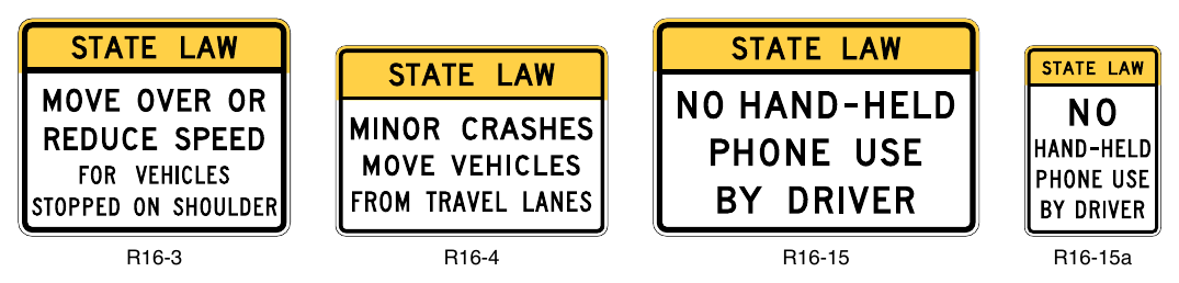
§2B.71 Move Over or Reduce Speed Sign (R16-3)¶
Option
01. A STATE LAW MOVE OVER OR REDUCE SPEED FOR VEHICLES STOPPED ON SHOULDER (R16-3) sign (see Figure 2B-33) may be installed in accordance with the provisions of Section 2A.01 to require motorists to change lanes and/or reduce speed when passing stopped emergency vehicles on the shoulder.
02. If the specific requirements of a State law vary, the word legend of the R16-3 sign may be modified to reflect the appropriate law.
§2B.72 No Hand-Held Phone Use by Driver Signs (R16-15 and R16-15a)¶
Option
01. A STATE LAW NO HAND-HELD PHONE USE BY DRIVER (R16-15 or R16-15a) sign (see Figure 2B-33) may be installed in accordance with the provisions of Section 2A.01 to notify drivers that they are prohibited from using hand-held telephones while driving.
02. If the specific requirements of a State law vary, the word legend of the R16-15 series signs may be modified to reflect the appropriate law.
§2B.73 Headlight Use Signs (R16-5 through R16-11)¶
Support
01. Some States require road users to turn on their vehicle headlights under certain weather conditions, as a safety improvement measure on roadways experiencing high crash rates, or in special situations such as when driving through a tunnel.
02. Figure 2B-34 shows the various signs that can be used for informing motorists of these requirements.
Option
03. A LIGHTS ON WHEN USING WIPERS (R16-5) sign or a LIGHTS ON WHEN RAINING (R16-6) sign may be installed in accordance with the provisions of Section 2A.01 to inform road users of State laws regarding headlight use. Although these signs are typically installed facing traffic entering the State just inside the State border, they also may be installed at other locations within the State.
Guidance
04. If a particular section of roadway has been designated as a safety improvement zone within which headlight use is required, a TURN ON HEADLIGHTS NEXT XX MILES (R16-7) sign or a BEGIN DAYTIME HEADLIGHT SECTION (R16-10) sign should be installed at the upstream end of the section, and an END DAYTIME HEADLIGHT SECTION (R16-11) sign should be installed at the downstream end of the section.
Option
05. A TURN ON HEADLIGHTS (R16-8) sign may be installed to require road users to turn on their headlights in special situations such as when driving through a tunnel. A CHECK HEADLIGHTS (R16-9) sign may be installed downstream from the special situation to inform drivers that using their headlights is no longer required.
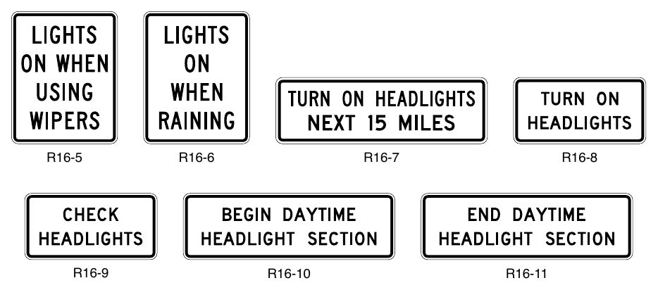
Signs shown: R16-5, R16-6, R16-7, R16-8, R16-9, R16-10, R16-11
§2B.74 Seat Belt Symbol¶
Guidance
01. The seat belt symbol should not be used alone. If used, the seat belt symbol should be incorporated into regulatory sign messages for mandatory seat belt use.
Support
02. The seat belt symbol is illustrated in the “Standard Highway Signs” publication (see Section 1A.05).
BARRICADES AND GATES¶
§2B.75 Barricades¶
Option
01. Barricades may be used to mark any of the following conditions:
- A. The end of a roadway,
- B. A ramp or lane that is closed for operational purposes, or
- C. The permanent or semi-permanent closure or termination of a roadway.
Standard
02. When used to warn and alert road users of the terminus of a roadway, other than in temporary traffic control zones, barricades shall meet the design criteria of Section 6K.07 for a Type 3 Barricade, except that the colors of the stripes shall be retroreflective white and retroreflective red.
Option
03. An end-of-roadway marker or markers may be used as described in Section 2C.73.
Guidance
04. Appropriate advance warning signs (see Chapter 2C) should be used.
§2B.76 Gates¶
Support
01. Gates described in this Section used for weather or other emergency conditions are typically permanently installed to enable the gate to be immediately deployed as needed to prohibit the entry of traffic to the highway segment(s).
02. A gate typically features a gate arm that is moved from a vertical to a horizontal position or is rotated in a horizontal plane from parallel to traffic to perpendicular to traffic. Traffic is obstructed and required to stop when the gate arm is placed in a horizontal position perpendicular to traffic. Another type of gate consists of a segment of fence (usually on rollers) that swings open and closed, or that is retracted to open and then extended to close.
03. Gates are sometimes used to enforce a required stop. Some examples of such uses are the following:
- A. Parking facility entrances and exits,
- B. Private community entrances and exits,
- C. Military base entrances and exits,
- D. Toll plaza lanes,
- E. Movable bridges (see Chapter 4Q),
- F. Automated Flagger Assistance Devices (see Chapter 6L), and
- G. Grade crossings (see Part 8).
04. Gates are sometimes used to periodically close a roadway or a ramp. Some examples of such uses are the following:
- A. Closing ramps to implement counter-flow operations for evacuations,
- B. Closing ramps that lead to reversible lanes, and
- C. Closing roadways for weather events such as snow, ice, or flooding, or for other emergencies.
Standard
05. Except as provided in Paragraph 6 of this Section, gate arms, if used, shall be fully retroreflective on both sides, have vertical stripes alternately red and white at 16-inch intervals measured horizontally as shown in Figure 8D-1. The width (which becomes the height of the retroreflective sheeting when the gate is in the down position) of the retroreflective sheeting on the front of the gate arm shall be at least 4 inches.
Option
06. If used on a one-way roadway or ramp, the retroreflective sheeting may be omitted on the side of the gate (or rolling fence) facing away from approaching traffic.
07. Where gate arms are used to block off ramps into reversible lanes or to redirect approaching traffic, the red and white striping may be angled such that the stripes slope downward at an angle of 45 degrees toward the side of the gate arm on which traffic is to pass.
Standard
08. The gate arm shall extend across the approaching lane or lanes of traffic to effectively block motor vehicle, bicycle, and/or pedestrian travel as appropriate.
Guidance
09. When a gate that is rotated in a horizontal plane is in the position where it is parallel to traffic (indicating that the roadway is open), the outer end of the gate arm should be rotated to the downstream direction (from the perspective of traffic in the lane adjacent to the gate support) to prevent spearing if the gate is struck by an errant vehicle.
Standard
10. If red lights are attached to a traffic gate, the red lights shall be steadily illuminated or flashed only during the period when the gate is in the horizontal or closed position and when the gate is in the process of being opened or closed.
11. Except as provided in Paragraph 6 of this Section, rolling sections of fence, if used, shall include either a horizontal strip of retroreflective sheeting on both sides of the fence with vertical stripes alternately red and white at 16-inch intervals measured horizontally to simulate the appearance of a gate arm in the horizontal position, or one or more Type 4 object markers (see Section 2C.73), or both. If a horizontal strip of retroreflective sheeting is used, the bottom of the sheeting shall be located 3.5 to 4.5 feet above the roadway surface.