Chapter 3J. Marking and Delineation of Islands and Sidewalk Extensions¶
§3J.01 General¶
Support
01. This Chapter addresses the marking and delineation of islands (see definition in Section 1C.02) and sidewalk extensions designated by pavement markings. Definitions, types, sizes, and other criteria for the design of islands are set forth in “A Policy on Geometric Design of Highways and Streets,” 2018 Edition, AASHTO.”
02. Section 3C.12 contains information on pedestrian islands and medians.
03. Sections 3H.04 and 3H.05 contain information on colored pavement that can be used within islands.
Option
04. An island may be designated by curbs, pavement edges, pavement markings, channelizing devices, or other devices.
§3J.02 Approach-End Treatment¶
Support
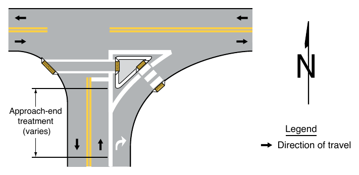
01. An approach-end treatment to an island consists of longitudinal pavement markings and/or channelizing devices upstream of the island followed by a divergence of those pavement markings and/or channelizing devices concluding with a transition to other pavement markings that demarcate or outline the island (see Figure 3J-1).
02. Section 3B.13 contains information on pavement markings that function as approach-end treatments for obstructions.
Guidance
03. The ends of islands first approached by traffic should be marked with an approach-end treatment, curb markings (see Section 3J.04), or both to guide vehicles into desired paths of travel along the island edge.
04. When raised bars or buttons that project more than 1 inch above the pavement surface are used to create a rumble section in the neutral area, the raised bars or buttons should be marked with white or yellow retroreflective materials, as determined by the direction or directions of travel they separate.
§3J.03 Islands Designated by Pavement Markings¶
Standard
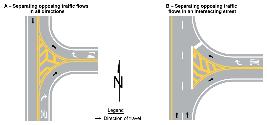
01. Except as provided in Paragraph 2 of this Section, islands formed by pavement markings only shall be established using channelizing lines, and shall be white when separating traffic flows in the same general direction or yellow when separating opposing directions of traffic.
02. If a continuous flush median island separating travel in opposite directions is used, two sets of double solid yellow lines shall be used to form the island (see Figure 3B-5). Other markings in the median island area, such as diagonal lines (see Section 3B.25), shall also be yellow, except crosswalk markings which shall be white (see Chapter 3C).
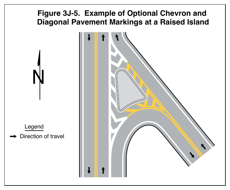
03. If used, chevron or diagonal markings (see Section 3B.25) within the island shall be the same color as the channelizing line.
Option
04. Both chevron and diagonal markings of the same color may be used within the same island based on engineering judgment.
05. The area within the flush island delineated by pavement markings may use colored pavement in accordance with the provisions of Chapter 3H.
Support
06. Figure 3J-2 illustrates examples of islands designated by pavement markings.
§3J.04 Curb Markings for Raised Islands¶
Standard
01. Where curbs are marked for delineation or visibility purposes, the colors shall comply with the general principles of markings (see Section 3A.03).
Guidance
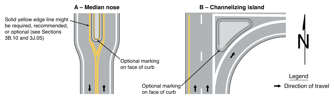
02. Retroreflective solid yellow curb markings should be placed on the approach ends of raised medians and curbs of islands that are located in the line of traffic flow where the curb serves to channel traffic to the right of the obstruction (see Figure 3J-3).
03. Retroreflective solid white curb markings should be used when traffic is permitted to pass on either side of the island (see Figure 3J-3).
04. The retroreflective area should be of sufficient length to denote the general alignment of the edge of the island along which vehicles travel, including the approach end, when viewed from the approach to the island.
Option
05. Where the curbs of the islands become parallel to the direction of traffic flow or where the island is illuminated or marked with delineators, curb markings may be discontinued based on engineering judgment or study.
06. Curb markings at openings in a continuous median island may be omitted based on engineering judgment or study.
§3J.05 Pavement Markings for Raised Islands¶
Support
01. Pavement markings for raised islands include the approach-end treatment (see Section 3J.02), channelizing lines, edge lines, and chevron or diagonal markings.
Option
02. Solid yellow edge lines (see Sections 3B.09 and 3B.10) may be used adjacent to raised islands separating travel in opposite directions (see Drawing A in Figure 3J-3).
Standard
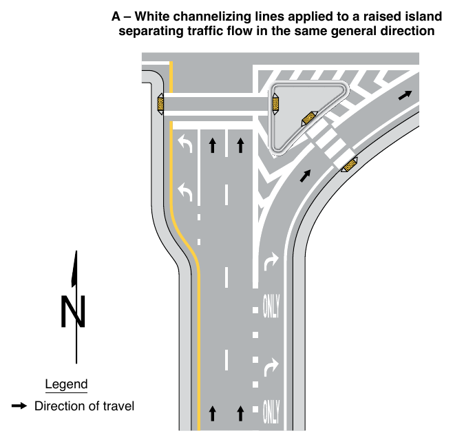
03. Except as provided in Paragraphs 4 and 6 of this Section, raised islands separating traffic flows in the same general direction shall be outlined with white channelizing lines (see Drawing A in Figure 3J-4).
Option
04. Pavement markings for smaller raised islands may be omitted based on engineering judgment.
Guidance
05. Smaller raised islands without marked channelizing lines, edge lines, or chevron or diagonal markings should use curb markings (see Section 3J.04).
06. Where traffic passes on the right of a raised island separating traffic flows in the same general direction, a yellow edge line should be used adjacent to raised islands of discernible size or length instead of continuing the white channelizing line from the approach-end treatment (see Drawing B in Figure 3J-4).
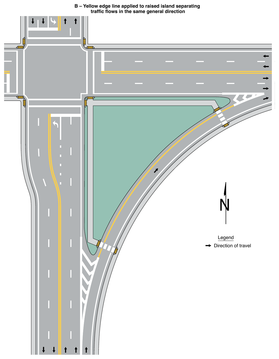
Support
07. Yellow edge lines adjacent to raised islands that separate traffic flows in the same general direction can be advantageous as a countermeasure for wrong-way entry or travel if the yellow edge line is of discernible length.
Option
08. Chevron markings may be used in neutral areas formed by diverging channelizing lines at raised islands separating traffic flows in the same general direction.
09. Diagonal markings of an appropriate color may be used in buffer areas between the channelizing line and the raised island (see Figure 3J-5).
§3J.06 Island Delineation¶
Standard
01. Delineators installed on islands shall be the same colors as the related channelizing or edge lines except that, when only facing wrong-way traffic, they shall be red (see Section 3G.03).
02. Each roadway through an intersection shall be considered separately in positioning delineators to assure maximum effectiveness.
Option
03. Retroreflective or internally illuminated raised pavement markers of the appropriate color may be placed on the pavement in front of the curb and/or on the top of curbed approach ends of raised medians and curbs of islands, as a supplement to or as a substitute for retroreflective curb markings.
§3J.07 Sidewalk Extensions Designated by Pavement Markings¶
Support
01. Sidewalk extensions reclaim a portion of the roadway, sometimes including a portion of parking lanes, shoulders, and/or the traveled way, and repurpose that area for non-vehicular uses. They extend the sidewalk or other pedestrian space, shorten pedestrian crossing distances, alter the roadway geometry for speed management or channelizing, or serve other purposes.
02. Sidewalk extensions, sometimes referred to as curb extensions, neckdowns, or bulb-outs, typically are created by physical infrastructure including concrete or asphalt to form a physical narrowing of the roadway with the finished surface at the same level as the adjoining sidewalk.
03. Sidewalk extensions can also be designated by pavement markings for temporary or semi-permanent applications in which the finished surface is at the same level as the vehicular travel pavement. Where an adjoining curb and raised sidewalk are present, this type of application results in a multi-level sidewalk due to the difference in elevation between the adjoining pedestrian surfaces.
04. Sidewalk extensions designated by pavement markings differ from other paved areas designated by pavement markings that are intended to be traversable by a vehicle for authorized or emergency purposes.
Standard
05. Sidewalk extensions designated by pavement markings shall be established using double solid lines connecting to the outside physical curb or, in the absence of a curb, to the edge of the roadway. The color of the double solid line shall comply with the provisions of Section 3A.03.
Support
06. The paved area between the double solid line forming the sidewalk extension designated by pavement markings and the sidewalk or other roadside area is not part of the roadway. Sidewalk extensions designated by pavement markings formed by double solid lines are distinct from areas such as shoulders or gore areas where travel is discouraged by the presence of a single line, or flush medians where travel is prohibited by a double solid line. Sidewalk extensions designated by pavement markings with double solid lines designate areas outside the roadway where vehicle traversal is prohibited.
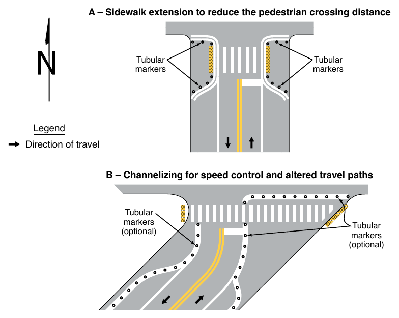
07. Areas formed by a single wide line are sometimes used to alter the roadway geometry for speed management or channelizing, or to serve other purposes, where pedestrians are not expected (see Drawing B in Figure 3J-6). These areas are not considered a sidewalk extension, and provisions to delineate areas where vehicle traversal is discouraged include channelizing lines (see Section 3B.08), edge lines (see Section 3B.09), and diagonal markings (see Section 3B.25).
Guidance
08. Channelizing devices such as tubular markers (see Chapter 3I) should be used to provide conspicuity for, and to prevent vehicles from traversing, the area of the sidewalk extension designated by pavement markings. They should be located adjacent to the double solid line outside the traveled way.
Support
09. When selecting other methods of physical separation, the visual contrast from adjoining pavement and maximum separation distances are considerations so they are visible to pedestrians having limited vision and detectable by pedestrians who travel with a long cane.
10. Sight lines and the visibility of road users within the sidewalk extension area are considerations when selecting methods of physical separation.
11. The swept path of turning design or other prevailing vehicle types is a consideration, especially if a larger vehicle is expected to traverse a portion of the sidewalk extension while turning where pedestrians might be present.
Standard
12. Crosswalk markings shall not be extended through sidewalk extensions designated by pavement markings.
Support
13. Accessibility provisions at sidewalk extensions designated by pavement markings are outside the scope of this Manual. State and local organizations providing support services to pedestrians with vision disabilities can provide advice to the traffic engineer on site-specific accessibility decisions. In addition, orientation and mobility specialists or similar staff can provide advice to inform such decisions. The U.S. Access Board (www.accessboard.gov) provides technical assistance for making pedestrian facilities accessible to persons with disabilities.
Guidance
14. Traffic control devices that are critical to the specific conditions at the sidewalk extension, such as STOP or YIELD signs or Pedestrian Crossing signs, should be located within the sidewalk extension designated by pavement markings. Their lateral offset (see Section 2A.16) should be measured from the center of the double solid line designating a sidewalk extension rather than from the physical curb line behind the sidewalk extension area so that the signs are more visible to approaching traffic and not occluded by any physical features placed within the sidewalk extension area.
Support
15. The location of accessible pedestrian signals (see Section 4K.02) is a consideration when providing a sidewalk extension designated by pavement markings.
16. Aesthetic surface treatments (see Chapter 3H) are sometimes used in sidewalk extensions designated by pavement markings to emphasize that the area is outside of the traveled way.
Standard
17. In accordance with the provisions of Section 3H.03, aesthetic surface treatments, if used within a sidewalk extension designated by pavement markings, shall be non-retroreflective.
Support
18. Figure 3J-6 illustrates an example of a sidewalk extension designated by pavement markings and an example of channelizing.