Chapter 8D. Flashing-Light Signals, Automatic Gates, and Traffic Control Signals¶
§8D.01 Introduction¶
Support
01. Active traffic control systems inform road users of the approach or presence of rail traffic at grade crossings. These systems include Exit Gate systems, automatic gates, flashing-light signals, traffic control signals, actuated blank-out and variable message signs, and other active traffic control devices that are used in conjunction with the signs and pavement markings that are described in Chapters 8B and 8C, respectively.
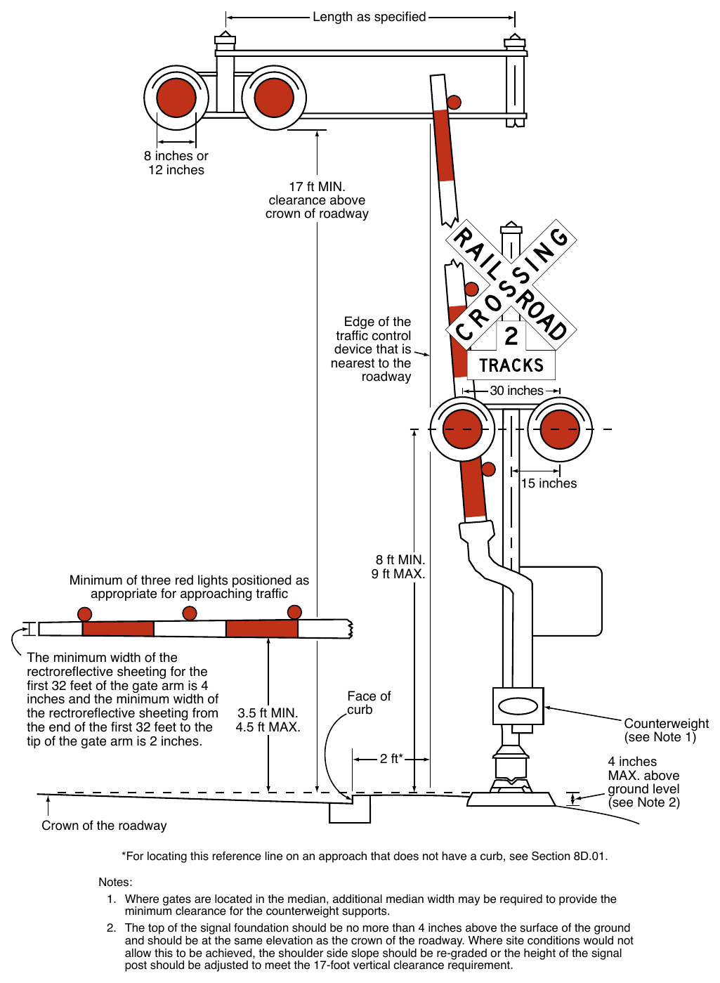
02. Figure 8D-1 shows a post-mounted flashing-light signal (two light units mounted in a horizontal line), a flashing-light signal mounted on an overhead structure, and an automatic gate assembly.
03. Where LRT speed is cited in this Part, it refers to the maximum speed at which LRT equipment is permitted to traverse a particular grade crossing.
Option
04. Post-mounted and overhead flashing-light signals may be used separately or in combination with each other as determined by the Diagnostic Team. Also, flashing-light signals may be used without automatic gate assemblies, as determined by the Diagnostic Team.
Standard
05. The meaning of flashing-light signals and automatic gates shall be as stated in Sections 11-701 and 11-703 of the Uniform Vehicle Code (see Section 1A.06).
06. Location for flashing-light signals and automatic gates shall be as shown in Figure 8D-1.
07. Where there is a curb, a horizontal offset of at least 2 feet shall be provided from the face of the vertical curb to the nearest part of the signal or automatic gate arm in its upright position. Where a cantilevered arm flashing-light signal is used, the vertical clearance shall be at least 17 feet above the crown of the highway to the lowest point of the signal unit.
08. Where there is a shoulder, but no curb, a horizontal offset of at least 2 feet from the edge of a paved shoulder shall be provided, with an offset of at least 6 feet from the edge of the traveled way.
09. Where there is no curb or shoulder, the minimum horizontal offset shall be 6 feet from the edge of the traveled way.
10. Minimum clearance dimensions for flashing-light signals and automatic gates relative to the closest track shall conform to standards provided by the railroad company and/or transit agency, and the regulatory agency with statutory authority (if applicable).
Guidance
11. Equipment housings (controller cabinets) should have a lateral offset of at least 30 feet from the edge of the highway, and where railroad or LRT property and conditions allow, at least 25 feet from the nearest rail.
12. If a pedestrian route is provided, sufficient clearance from supports, posts, and automatic gate mechanisms should be maintained for pedestrian travel.
13. Where determined by the Diagnostic Team, a lateral escape route to the right-hand side of the highway in advance of the grade crossing traffic control devices should be kept free of guardrail or other ground obstructions. Where guardrail is not deemed necessary or appropriate, barriers should not be used for protecting signal supports.
14. The same lateral offset and roadside safety features should apply to flashing-light signal and automatic gate locations on both the right-hand and left-hand sides of the roadway.
Option
15. In industrial or other areas involving only low-speed highway traffic or where signals are vulnerable to damage by turning truck traffic, guardrail may be installed to provide protection for the signal assembly.
Guidance
16. Where both traffic control signals and flashing-light signals (with or without automatic gates) are in operation at the same highway-LRT grade crossing, the operation of the devices should be coordinated to avoid any display of conflicting signal indications.
Option
17. If highway traffic signals must be located within close proximity to the flashing-light signals, the highway traffic signals may be mounted on the same overhead structure as the flashing-light signals.
§8D.02 Flashing-Light Signals¶
Support
01. Section 8D.04 contains additional information regarding flashing-light signals at highway-LRT grade crossings in semi-exclusive and mixed-use alignments.
Standard
02. If used, the flashing-light signal assembly (shown in Figure 8D-1) on the side of the highway shall include a standard Crossbuck (R15-1) sign, and where there is more than one track, a supplemental Number of Tracks (R15-2P) plaque, all of which indicate to motorists, bicyclists, and pedestrians the location of a grade crossing.
Guidance
03. The bottom of the Number of Tracks (R15-2P) plaque (when used) should be located as low as practicable above the flashing-light backgrounds. The Crossbuck (R15-1) sign should be located just above the Number of Tracks (R15-2P) plaque or, if no plaque is present, the bottom of the Crossbuck sign should be located as low as practicable above the flashing-light backgrounds.
Support
04. Additional information regarding sizes and clearances of components used on flashing-light signals can be found in Part 3 of the “2023 AREMA Communications and Signals Manual” published by the American Railway Engineering and Maintenance-of-Way Association (AREMA).
Option
05. At highway-rail grade crossings, bells or other audible warning devices may be included in the assembly and may be operated in conjunction with the flashing-light signals to provide additional warning for pedestrians, bicyclists, and/or other non-motorized road users.
Standard
06. When indicating the approach or presence of rail traffic, the flashing-light signal shall display toward approaching highway traffic two red lights mounted in a horizontal line flashing alternately.
07. If used, flashing-light signals shall be placed to the right-hand side of approaching highway traffic on all highway approaches to a grade crossing. They shall be located laterally with respect to the highway in compliance with Figure 8D-1 except where such location would adversely affect signal visibility.
08. If used at a grade crossing with highway traffic in both directions, back-to-back flashing-light signals shall be placed on each side of the tracks. On multi-lane one-way streets and divided highways, flashing-light signals shall be placed on the approach side of the grade crossing on both sides of the roadway or shall be placed above the highway.
09. Each red signal unit in the flashing-light signal shall flash alternately. The number of flashes per minute for each lamp shall be 35 minimum and 65 maximum. Each lamp shall be illuminated for approximately the same length of time. The total time of illumination of each pair of lamps shall be the entire operating time.
10. Flashing-light units shall use either 8-inch or 12-inch nominal diameter lenses.
Guidance
11. In choosing between the 8-inch or 12-inch nominal diameter lenses for use in grade crossing flashing-light signals, consideration should be given to the principles stated in Section 4E.02.
12. If flashing-light signals are used, at least one pair of flashing lights should be provided for each approach lane of the roadway.
13. The center-to-center distance between the two red lights in a flashing-light unit should be approximately 30 inches.
14. The mounting height of the flashing-light units, measured from the center of the flashing-light unit housing to the elevation of the crown of the roadway, should be between 8 feet and 9 feet .
15. The top of the support pole foundation should be no more than 4 inches above the surface of the ground and should be at the same elevation as the crown of the roadway.
Standard
16. Grade crossing flashing-light signals shall operate at a low voltage using storage batteries either as a primary or stand-by source of electrical energy. Provision shall be made to provide a source of energy for charging batteries.
Option
17. Additional flashing-light signals may be mounted on the same supporting post and directed toward vehicular traffic approaching the grade crossing from other than the principal highway route, such as where there are approaching routes on highways closely adjacent to and parallel to the track(s).
Guidance
18. Where the storage distance for vehicles approaching a grade crossing is less than a design vehicle length, the Diagnostic Team should consider providing additional flashing-light signals aligned toward the movement turning toward the grade crossing.
19. The Diagnostic Team should consider the use of additional flashing-light signals to provide supplemental warning to pedestrians, especially on one-way streets and divided highways.
Standard
20. References to lenses in this Section shall not be used to limit flashing-light signal optical units to incandescent lamps within optical assemblies that include lenses.
Support
21. Research has resulted in flashing-light signal optical units that are not lenses, such as, but not limited to, lightemitting diode (LED) flashing-light signal modules.
Option
22. If a Diagnostic Team determines that it is appropriate, the flashing-light signals may be installed on overhead structures or cantilevered supports as shown in Figure 8D-1 where needed for additional emphasis, or for better visibility to approaching traffic, particularly on multi-lane approaches or highways with profile restrictions.
23. If it is determined by a Diagnostic Team that one flashing-light signal on the cantilever arm is not sufficiently visible to road users, one or more additional flashing-light signals may be mounted on the supporting post and/or on the cantilever arm.
Standard
24. Breakaway or frangible bases shall not be used on the supporting posts for overhead structures or cantilevered arms that support overhead flashing-light signals.
§8D.03 Automatic Gates¶
Support
01. An automatic gate is a traffic control device used in conjunction with flashing-light signals.
Standard
02. The automatic gate (see Figure 8D-1) shall consist of a drive mechanism and a fully retroreflective redand-white-striped gate arm with lights. When in the down position, the gate arm shall extend across the approaching lanes of highway traffic.
03. In the normal sequence of operation, unless constant warning time detection or other advanced system requires otherwise, the flashing-light signals and the lights on the gate arm (in its normal upright position) shall be activated immediately upon detection of approaching rail traffic. The gate arm shall start its downward motion not less than 3 seconds after the flashing-light signals start to operate, shall reach its horizontal position at least 5 seconds before the arrival of the rail traffic, and shall remain in the down position until the rail traffic completely clears the grade crossing.
04. When the rail traffic clears the grade crossing, and if no other rail traffic is detected, the gate arm shall ascend to its upright position, following which the flashing-light signals and the lights on the gate arm shall cease operation.
05. Gate arms shall be fully retroreflective on both sides and shall have vertical stripes alternately red and white at 16-inch intervals measured horizontally. The width (which becomes the height of the retroreflective sheeting when the automatic gate is in the down position) of the retroreflective sheeting on the front of the gate arm shall be at least 4 inches for the first 32 feet of gate arm length measured from the center of the gate mast. The front of the gate arm beyond 32 feet to the tip of the gate arm shall have retroreflective sheeting at least 2 inches in width.
Support
06. It is acceptable to replace a damaged gate arm with a gate arm having vertical stripes even if the other existing gate arms at the same grade crossing have diagonal stripes; however, it is also acceptable to replace a damaged gate arm with a gate arm having diagonal stripes if the other existing gate arms at the same grade crossing have diagonal stripes in order to maintain consistency per the provisions of Paragraph 13 of Section 1B.03.
Standard
07. Gate arms shall have at least three red lights as shown in Figure 8D-1.
08. When activated, the gate arm light nearest the tip shall be illuminated continuously and the other lights shall flash alternately in unison with the flashing-light signals such that the left-most flashing gate arm light(s) flashes simultaneously with the left-hand light of the flashing-light signals and the right-most flashing gate arm light(s) flashes simultaneously with the right-hand light of the flashing-light signals.
Support
09. Typical gate arm lights are approximately 4 inches in diameter if they are circular. Rectangular gate arm lights with approximately the same illuminated surface area are sometimes used on gate arms instead of circular lights.
Standard
10. The entrance gate arm mechanism shall be designed to fail-safe in the down position.
Guidance
11. The gate arm should ascend to its upright position in 12 seconds or less.
12. In its normal upright position, when no rail traffic is approaching or occupying the grade crossing, the gate arm should be approximately vertical (see Figure 8D-1).
13. In the design of individual installations, consideration should be given to timing the operation of the gate arm to accommodate large and/or slow-moving motor vehicles.
14. The gate arms should cover the approaching highway to block all motor vehicles from being driven around the gate arms without crossing the center line.
15. The height of the gate arm when it is in the down position should be between 3.5 feet and 4.5 feet above the crown of the roadway. When the gate arm is in the down position, no portion of the counterweight should extend into the traveled way, sidewalk, or pathway.
Option
16. Channelizing devices and/or raised median islands may be used to discourage driving around lowered automatic gates.
Guidance
17. Where sufficient space is available, median islands should be at least 60 feet in length.
Option
18. Where automatic gates are located in the median, additional median width may be required to provide the minimum clearance for the counterweight supports.
19. Automatic gates may be supplemented by cantilevered flashing-light signals (see Figure 8D-1) where there is a need for additional emphasis or better visibility.
§8D.04 Use of Active Traffic Control Systems at LRT Grade Crossings¶
Standard
01. At highway-LRT grade crossings where LRT speeds exceed 25 mph, active traffic control systems (see Section 8D.01) shall be used.
02. At highway-LRT grade crossings where LRT speeds exceed 40 mph, the active traffic control system shall include automatic gates.
Option
03. The Diagnostic Team may recommend an active traffic control system with automatic gates at highway-LRT grade crossings where LRT speeds do not exceed 40 mph.
Guidance
04. At highway-LRT grade crossings where LRT speeds are 25 mph or less, active traffic control systems should be used unless the Diagnostic Team determines that the use of Crossbuck Assemblies, traffic control signals, STOP signs alone, or YIELD signs alone would be adequate.
05. Where the highway-LRT grade crossing is at a location other than an intersection or in the median of a highway or street and LRT speeds exceed 20 mph, traffic control signals should not be used in lieu of flashing-light signals.
Support
06. Section 8A.04 contains additional provisions for LRT grade crossing in semi-exclusive alignments. Sections 8D.02 and 8D.03 contain additional provisions regarding the design and operation of flashing-light signals and automatic gates, respectively.
Standard
07. If flashing-light signals are in operation at a highway-LRT crossing that is used by pedestrians, bicyclists, and/or other non-motorized road users, an audible device such as a bell shall also be provided and shall be operated in conjunction with the flashing-light signals.
§8D.05 Exit Gate and Four-Quadrant Gate Systems¶
Option
01. Exit Gate systems may be installed to improve safety at grade crossings where a Diagnostic Team determines that less restrictive measures, such as automatic gates and median islands, are not effective.
Support
02. A grade crossing that includes exit gates on some, but not all, of the exiting lanes is an Exit Gate system, but is not considered to be a Four-Quadrant Gate system.
03. The term Four-Quadrant Gate system is used in a generic sense in that it refers to the fact that all entrances and exits from a grade crossing are controlled by automatic gates in order to provide a full closure to all entering and exiting lanes. The term Four-Quadrant Gate system does not refer to the number of gates installed, but rather the fact that a full closure is provided.
Standard
04. The Exit Gate system shall use a series of automatic gates with fully retroreflective red-and-whitestriped gate arms with lights, and when in the down position the gate arms extend individually across the entrance and exit lanes of the roadway as shown in Figure 8D-2. The provisions contained in Section 8D.02 for flashing-light signals shall be followed for signal specifications, location, and clearance distances.
05. Gate arm design, colors, and lighting requirements shall be in accordance with the provisions contained in Section 8D.03.
Support
06. The provisions contained in Section 8D.03 for automatic gates are applicable to exit gates.
Standard
07. In the normal sequence of operation, unless constant warning time detection or other advanced system requires otherwise, the flashing-light signals and the lights on the gate arms (in their normal upright positions) shall be activated immediately upon the detection of approaching rail traffic. The entrance gate arms shall start their downward motion not less than 3 seconds after the flashing-light signals start to operate and shall reach their horizontal position at least 5 seconds before the arrival of the rail traffic. Exit gate arm activation and downward motion shall be based on detection or timing requirements established by a Diagnostic Team. If an Exit Gate system is present, the exit gate clearance time (see AREMA Manual) shall be long enough to permit the exit gate arm to lower after a design vehicle of maximum length is clear of the minimum track clearance distance (see Section 8A.07). The gate arms shall remain in the down position as long as the rail traffic occupies the grade crossing.
08. When the rail traffic clears the grade crossing, and if no other rail traffic is detected, the gate arms shall ascend to their upright positions, following which the flashing-light signals and the lights on the gate arms shall cease operation.
09. Except as provided in Paragraph 21 of this Section, the exit gate arm mechanism shall be designed to fail-safe in the up position.
10. At locations where gate arms are offset a sufficient distance for motor vehicles to drive between the entrance and exit gate arms, median islands (see Figure 8D-2) shall be installed in accordance with the needs determined by the Diagnostic Team.
Guidance
11. The gate arm should ascend to its upright position in 12 seconds or less.
12. Constant warning time detection circuits should be used with Exit Gate systems where practical.
13. The operating mode of the exit gates should be determined by a Diagnostic Team.
14. If the Timed Exit Gate Operating Mode is used, the Diagnostic Team should also determine the Exit Gate Clearance Time (see definition in Section 1C.02).
15. If the Dynamic Exit Gate Operating Mode is used, highway vehicle intrusion detection devices that are part of a system that incorporates processing logic to detect the presence of motor vehicles within the minimum track clearance distance (see Section 8A.07) should be installed to control exit gate operation. Exit gates should be independently controlled for each direction of roadway traffic.
16. Regardless of which exit gate operating mode is used, the Exit Gate Clearance Time should be considered when determining additional time requirements for the Minimum Warning Time.
Support
17. The minimum warning time is the least amount of time that active warning devices operate prior to the arrival of rail traffic at a grade crossing.
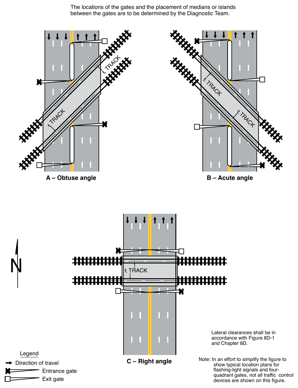
between the gates are to be determined by the Diagnostic Team. A – Obtuse angle B – Acute angle Lateral clearances shall be in accordance with Figure 8D-1 and Chapter 8D. Legend Direction of travel Entrance gate Exit gate C – Right angle Note: In an effort to simplify the figure to show typical location plans for flashing-light signals and four-quadrant gates, not all traffic control devices are shown on this figure.
Guidance
18. If an Exit Gate system is used at a location that is adjacent to an intersection that could cause motor vehicles to queue within the minimum track clearance distance (see Section 8A.07), the Dynamic Exit Gate Operating Mode should be used unless the Diagnostic Team determines otherwise.
19. If an Exit Gate system is interconnected with a highway traffic signal (see Section 8D.09), back-up or standby power should be considered for the highway traffic signal. Also, circuitry should be installed to prevent the highway traffic signal from leaving the track clearance green interval until all of the gates are lowered.
20. Exit Gate systems should include remote health (status) monitoring capable of automatically notifying railroad or LRT signal maintenance personnel when anomalies have occurred within the system.
Option
21. Exit gate arms may fail in the down position if the grade crossing is equipped with remote health (status) monitoring.
22. Exit Gate system installations may include median islands between opposing lanes on an approach to a grade crossing.
Guidance
23. Where sufficient space is available, median islands should be at least 60 feet in length.
§8D.06 Wayside Horn Systems¶
Option
01. A wayside horn system (see definition in Section 1C.02) may be installed in compliance with 49 CFR Part 222 to provide audible warning directed toward the road users at a highway-rail grade crossing or at a pathway grade crossing.
Standard
02. Wayside horn systems used at grade crossings where the locomotive horn is not sounded shall be equipped and shall operate in compliance with the requirements of Appendix E to 49 CFR Part 222.
Guidance
03. The same lateral clearance and roadside safety features should apply to wayside horn systems as described in the provisions contained in Section 8D.01. Wayside horn systems, when mounted on a separate pole assembly, should be installed no closer than 15 feet from the center of the nearest track and should be positioned to not obstruct the motorists’ line of sight of the flashing-light signals.
§8D.07 Rail Traffic Detection¶
Standard
01. The devices employed in active traffic control systems shall be actuated by some form of rail traffic detection.
02. Rail traffic detection circuits, insofar as practical, shall be designed on the fail-safe principle.
03. Flashing-light signals shall operate for at least 20 seconds before the arrival of any rail traffic, except as provided in Paragraph 4 of this Section.
Option
04. On tracks where all rail traffic operates at less than 20 mph and where road users are directed by an authorized person on the ground to not enter the crossing at all times that approaching rail traffic is about to occupy the crossing, a shorter signal operating time for the flashing-light signals may be used.
05. Additional warning time may be provided when determined by an engineering study.
Guidance
06. Where the speeds of different rail traffic on a given track vary considerably under normal operation, special devices or circuits should be installed to provide reasonably uniform notice in advance of all rail traffic movements over the grade crossing. Special control features should be used to eliminate the effects of station stops and switching operations within approach control circuits to prevent excessive activation of the traffic control devices while rail traffic is stopped on or switching upon the approach track control circuits.
§8D.08 Use of Traffic Control Signals at Grade Crossings¶
Standard
01. Except as provided in Paragraph 2 of this Section, traffic control signals shall not be used instead of flashing-light signals to control road users at a highway-rail grade crossing.
Option
02. Traffic control signals may be used instead of flashing-light signals to control road users at industrial highway-rail grade crossings and other places where the maximum speed of trains is 10 mph or less.
Support
03. Sections 8D.04 and 8D.14 contain information regarding the use of traffic control signals at highway-LRT grade crossings.
Standard
04. The appropriate provisions of Part 4 relating to traffic control signal design, installation, and operation shall be applicable where traffic control signals are used instead of flashing-light signals to control road users at grade crossings.
§8D.09 Preemption of Highway Traffic Signals at or Near Grade Crossings¶
Support
01. Traffic signal preemption for grade crossings is a complex topic that requires a specific understanding of grade crossing warning systems and highway traffic signal operations. While most traffic signal operations are governed only by the traffic signal controller unit and the associated traffic signal equipment, preemption for grade crossings is also governed by the grade crossing warning system. Active grade crossing warning systems include flashing-light signals and possibly automatic gates, as well as various types of train detection equipment. Where the traffic signal controller unit is interconnected with the grade crossing warning system for the purpose of preemption, a combined system is created. It is the combined system that requires a thorough understanding of the design and operating parameters in order to provide proper operation of the preemption system.
02. The Federal Railroad Administration (FRA) has issued two documents that provide additional information relating to preemption of highway traffic signals at or near grade crossings. The first document is “Technical Bulletin S-12-01, Guidance Regarding the Appropriate Process for the Inspection of Highway-Rail Grade Crossing Warning System Pre-emption Interconnections with Highway Traffic Signals” and the second document is “Safety Advisory 2010-02, Signal Recording Devices for Highway-Rail Grade Crossing Active Warning Systems that are Interconnected with Highway Traffic Signal Systems.”
Guidance
03. If a grade crossing is equipped with flashing-light signals and is located 200 feet or less from an intersection or midblock location controlled by a traffic control signal, a pedestrian hybrid beacon, or an emergency-vehicle hybrid beacon, the intersection should be provided with rail preemption in accordance with Section 4F.19 unless otherwise determined by the Diagnostic Team.
04. Coordination with the flashing-light signals, such as using queue detection and queue cutter signals, blank-out signs, or other alternatives, should be considered where a traffic control signal, a pedestrian hybrid beacon, or an emergency-vehicle hybrid beacon is located more than 200 feet from the grade crossing. Factors to be considered should include traffic volumes, highway vehicle mix, highway vehicle and train approach speeds, frequency of trains, presence of midblock driveways or unsignalized intersections, and the potential for vehicular queues resulting from an adjacent downstream grade crossing or highway traffic signal to extend into the minimum track clearance distance (see Section 8A.07).
05. The highway agency or authority with jurisdiction and the regulatory agency with statutory authority, if applicable, should jointly determine the preemption operation and the timing of highway traffic signals interconnected with grade crossings adjacent to signalized locations.
06. If a highway traffic signal is installed 200 feet or less from a passive grade crossing, unless otherwise determined by the Diagnostic Team, an active grade crossing warning system should be installed at the grade crossing to provide a means to preempt the highway traffic signal in order to clear vehicles from the minimum track clearance distance (see Section 8A.07) upon approach of rail traffic.
07. If a highway traffic signal is interconnected with flashing-light signals, the flashing-light signals should be provided with automatic gates to prevent additional vehicles from being drawn into the minimum track clearance distance (see Section 8A.07) during the track clearance interval prior to the arrival of rail traffic unless a Diagnostic Team determines otherwise.
Support
08. Regular joint inspections by the highway agency or authority with jurisdiction, the regulatory agency with statutory authority, if applicable, and the railroad company or transit agency are a best practice and typically include verification of the preemption operation, the amount of warning time and/or preemption time being provided by the grade crossing warning system, and the timing of highway traffic signals interconnected and/or coordinated with the flashing-light signals.
09. Section 4F.19 includes a recommendation that traffic control signals that are adjacent to highway-rail grade crossings and that are coordinated with the flashing-light signals at the grade crossing or that include railroad preemption features be provided with a back-up power supply.
Standard
10. Information regarding the type of preemption and any related timing parameters shall be provided to the railroad company or transit agency so that the railroad company or transit agency can design the appropriate train detection circuitry.
11. If preemption is provided, unless otherwise determined by a Diagnostic Team, the normal sequence of highway traffic signal indications shall be preempted upon the approach of a train to provide a track clearance interval to provide an opportunity for motor vehicles at the grade crossing to clear the minimum track clearance distance (see Section 8A.07) prior to the arrival of rail traffic.
Option
12. Where train switching or train restarts occur close to a grade crossing, the Diagnostic Team may determine that the preemption time can be reduced in accordance with the operating requirements of the railroad company and/or transit agency.
Standard
13. Where flashing-light signals are in place at a grade crossing, any highway traffic signal faces installed within 50 feet of any rail shall be preempted upon the approach of rail traffic. The Diagnostic Team shall determine the signal indications displayed by the highway traffic signal faces that control movements across the grade crossing in accordance with Section 4F.19 in order to avoid the display of signal indications that conflict with the flashing-light signals.
Guidance
14. Where the flashing-light signals are in place at a grade crossing, the operation of any flashing yellow beacon installed within 50 feet of any rail should be considered by a Diagnostic Team to determine whether the operation of the beacon should be terminated during the approach and passage of rail traffic.
Standard
15. The preemption special control mode shall be activated by a supervised preemption interconnection using fail-safe design principles between the control circuits of the grade crossing warning system and the traffic signal controller unit. The approach of rail traffic to a grade crossing shall de-energize the interconnection or send a message via a fail-safe data communication protocol (such as the “IEEE Standard for the Interface Between the Rail Subsystem and the Highway Subsystem at a Highway Rail Intersection,” 1570-2002 (R2008), Institute of Electrical and Electronics Engineers), which in turn shall activate the traffic signal controller preemption sequence. This shall establish and maintain the preemption condition during the time the grade crossing warning system is activated, except that when automatic gates exist, the preemption condition shall not be terminated until the automatic gates are energized to start their upward movement.
Support
16. Advance preemption is the notification of approaching rail traffic that is forwarded to the highway traffic signal controller unit or assembly by the railroad or light rail transit equipment in advance of the activation of the grade crossing warning system.
17. The maximum preemption time is the maximum amount of time needed following initiation of the preemption sequence for the highway traffic signals to complete the timing of the right-of-way transfer time, queue clearance time, and separation time.
18. The separation time is the component of maximum preemption time during which the minimum track clearance distance is clear of vehicular traffic prior to the arrival of rail traffic.
19. Simultaneous preemption is the notification of approaching rail traffic that is forwarded to the highway traffic signal controller unit or assembly and grade crossing warning system at the same time.
20. The right-of-way transfer time is the amount of time needed prior to display of the track clearance interval. This includes any time needed by the railroad, light rail transit, or highway traffic signal control equipment to react to a preemption call, and any traffic control signal green, pedestrian walk and clearance if used (see Section 4F.19), yellow change, and red clearance intervals for conflicting traffic.
21. A supervised preemption interconnection is one that incorporates both a normally-open and a normally-closed circuit from the grade crossing warning system to verify the proper operation of the interconnection.
Option
22. Instead of supervision, a double-break preemption interconnection circuit that uses two normally-closed circuits that open both the source and return energy circuits may be used.
23. A preemption interconnection may incorporate both supervision and double-break circuits.
Guidance
24. Where train detection circuits are present at a passive grade crossing, the operation of the preemption interconnection should be treated as if active traffic control devices exist at the crossing and the preemption operation should be determined by a Diagnostic Team.
25. Where left turns are permitted at a downstream highway-highway traffic control signal from the roadway approach that crosses the track and a delayed or impeded left-turn movement could prevent vehicles from clearing the track, a protected left-turn movement should be provided during the track clearance interval if green signal indications are displayed to the approach for track clearance.
26. The decision to implement simultaneous or advance preemption should include consideration of the right-of-way transfer time, the queue clearance time, and the separation time in order to determine the maximum preemption time. These time periods should be compared to and verified with the operation of the grade crossing traffic control devices in order to evaluate the operation of the highway traffic signal and the preemption operation. These factors should be considered regardless of whether simultaneous or advance preemption operation is implemented as they are based on traffic signal minimum timing, vehicle acceleration characteristics, and physical distances along the roadway.
Support
27. Preemption time variability occurs when the traffic signal controller enters the preemption clearance interval with less than the maximum design right-of-way transfer time or when the speed of a train approaching the grade crossing varies.
28. The time interval between the initiation of advance preemption and the operation of the grade crossing warning system for rail traffic will decrease in situations when rail traffic is accelerating or increase in situations when rail traffic is decelerating.
Guidance
29. Where preemption is used and automatic gates are present, the possibility that an automatic gate might descend upon a vehicle should be analyzed.
30. If simultaneous preemption is used, an analysis of extended grade crossing warning time requirements should be conducted.
31. If advance preemption is used, an analysis of preemption operation, traffic signal sequencing, and traffic signal phasing should be conducted to identify preemption time variability. The analysis should include both the condition requiring the longest amount of time to enter the track clearance interval and the condition requiring the shortest amount of time to enter the track clearance interval.
Standard
32. Where automatic gates are present and green signal indications are displayed at the downstream traffic control signal during the track clearance interval, the preemption sequence shall be designed such that the green signal indications are not terminated until the automatic gate(s) that controls access over the grade crossing toward the downstream intersection is fully lowered.
Support
33. The following are two examples of mutually-exclusive methods to resolve preemption time variability:
- A. Gate-down circuitry provides a means to hold the traffic signal controller sequence in the track clearance interval until the automatic gate(s) that controls access over the grade crossing toward the downstream intersection is fully lowered.
- B. Timing correction resolves preemption time variability by adding the right-of-way transfer time to the track clearance interval in the traffic signal controller unit and setting a fixed maximum period of time between the start of advance preemption and the operation of the flashing-light signals.
34. The Third Edition of the “Railroad-Highway Grade Crossing Handbook” and the “2023 AREMA Communications and Signals Manual” published by the American Railway Engineering and Maintenance-of-Way Association (AREMA) provide additional information about preemption time variability.
Standard
35. Where gate-down circuitry is used to resolve preemption time variability and an automatic gate is broken or is not fully lowered, the crossing control circuits shall not terminate the track clearance interval before the rail traffic has entered the grade crossing.
36. Where timing correction is used to resolve preemption time variability, a timing circuit shall be used to maintain a maximum time interval between the initiation of advance preemption and the operation of the grade crossing warning system when the approaching rail traffic is decelerating.
Guidance
37. Where a highway-highway intersection controlled by traffic control signals is interconnected with a grade crossing equipped with exit gates, advance preemption should be used because of the additional operating time that is required for the exit gates.
38. Where rail traffic routinely stops and re-starts within or just outside of the approaches to a grade crossing that is interconnected with highway traffic signals, the effects of rail traffic operations on the preemption operation should be analyzed.
39. Highway traffic signal control equipment should be capable of providing immediate re-service of successive requests for preemption from the railroad warning devices, even if the initial preemption sequence has not been completed. As appropriate, the highway traffic signal control equipment should be able to promptly return to the start of the track clearance interval at any time that the demand for preemption is cancelled and then reactivated. The highway traffic signal control equipment should have the ability to provide this immediate re-service at any point in the preemption sequence.
Standard
40. Where traffic control signals are programmed to operate in a flashing mode during the preemption dwell interval (the period following the track clearance interval that lasts for the duration of the preemption interconnection activation), the beginning of the preemption dwell flashing mode shall not occur until the grade crossing equipment indicates that the rail traffic has entered the grade crossing.
41. At locations where conflicting preemption calls might be received to serve boats and trains, the Diagnostic Team shall determine the relative priority when conflicting preemption calls occur (see Section 4F.19). Where the boat and the train do not conflict with each other, the Diagnostic Team shall determine the preemption sequence when both preemption calls are occurring simultaneously. The United States Coast Guard or other appropriate authority that regulates the operation of the waterway shall be invited to participate on the Diagnostic Team and/or to provide input to the Diagnostic Team.
Support
42. Section 4C.10 describes the Intersection Near a Grade Crossing signal warrant that is intended for use at a location where the proximity to the intersection of a grade crossing on an intersection approach controlled by a STOP or YIELD sign is the principal reason to consider installing a traffic control signal.
43. Section 4F.19 describes additional considerations regarding preemption of traffic control signals at or near grade crossings.
§8D.10 Movements Prohibited During Preemption¶
Guidance
01. At a signalized intersection that is located within 100 feet of a grade crossing and the intersection traffic control signals are preempted by the approach of rail traffic, all existing permissive-only turning movements toward the grade crossing should be prohibited, steady red arrow signal indications should be shown to all existing protected/permissive and protected-only turning movements toward the grade crossing, and red signal indications should be shown to the straight-through movement toward the grade crossing during the signal preemption sequences. The prohibition of a permissive-only turning movement toward the grade crossing during preemption should be accomplished through the installation of a blank-out turn prohibition (R3-1a or R3-2a) sign (see Figure 8B-1).
Option
02. All movements toward the track may be prohibited at a signalized intersection that is preempted by the approach of rail traffic, even if the clear storage distance is more than 100 feet.
Support
03. Including the word “TRAIN” as part of the blank-out turn prohibition sign informs road users that the turn prohibition being displayed by the sign is in effect because rail traffic is approaching or occupying a nearby rail grade crossing, and that the turn prohibition will be terminated after the rail traffic has cleared the grade crossing.
04. Rail operations can include the use of activated blank-out turn prohibition (R3-1a or R3-2a) signs at unsignalized highway-highway intersections in the vicinity of grade crossings, such as where a semi-exclusive or mixed-use alignment is within or parallel to the roadway where road users are normally permitted to turn across the tracks.
Guidance
05. An LRT-activated blank-out turn prohibition (R3-1a or R3-2a) sign should be used during preemption where all three of the following conditions are present:
- A. There is no active warning system for the LRT grade crossing,
- B. Vehicles traveling along a parallel roadway would normally be permitted to turn left or right to travel across tracks that are located within 100 feet of the highway-highway intersection or within the median of the intersection, and C. The drivers turning at the highway-highway intersection are not prohibited from turning left or right by a separate traffic signal face with a red arrow.
Standard
06. Blank-out turn prohibition signs that are associated with preemption shall display their message only when a preemption signal is being received from the railroad or LRT equipment or while the automatic gate is activated.
Support
07. The provisions contained in Chapter 2L for blank-out signs are applicable to R3-1a and R3-2a signs.
§8D.11 Pre-Signals at or Near Grade Crossings¶
Guidance
01. If a grade crossing is located in close proximity to an intersection controlled by a traffic control signal and the clear storage distance is less than the design vehicle length, the use of pre-signals to control traffic approaching the grade crossing in the direction toward the intersection should be considered.
02. If a grade crossing equipped with flashing-light signals, but without automatic gates, is located within 200 feet of an intersection controlled by a traffic control signal, a pre-signal should be provided.
Support
03. A pre-signal is generally used where the grade crossing is located less than 200 feet from a downstream signalized intersection. Section 8D.12 contains information for grade crossings located 200 feet or more from a downstream signalized intersection.
04. Other measures that could be considered instead of or in addition to a pre-signal to minimize the possibility of vehicles queuing across the grade crossing include providing additional lanes, reducing the cycle length, using split phasing, using protected turn phasing, and/or providing an extended green interval for the approach.
Standard
05. Pre-signal faces shall display a steady red signal indication during the track clearance interval of the signal preemption sequence to prohibit additional motor vehicles from entering the minimum track clearance distance (see Section 8A.07).
06. Pre-signal faces shall not display green signal indications when the grade crossing flashing-light signals are displaying flashing red indications.
Guidance
07. Consideration should be given to using visibility-limited signal faces (see definition in Section 1C.02) at the intersection for the downstream signal faces that control the approach that is equipped with pre-signals.
Option
08. The duration of the extended green interval may be adjusted by vehicle detection located between the presignal and the downstream signalized intersection.
09. The pre-signal phase sequencing may be timed with an offset from the downstream signalized intersection such that the pre-signal’s green signal indication terminates prior to the downstream intersection’s green signal indication to minimize the possibility of stopping motor vehicles within the minimum track clearance distance (see Section 8A.07) and the clear storage distance .
Guidance
10. If pre-signals are used, the queue clearance time (see Section 8D.09) should be long enough to allow a design vehicle of maximum length stopped just inside the minimum track clearance distance (see Section 8A.07) to start up and move through the downstream intersection, or to clear the minimum track clearance distance if there is sufficient clear storage distance.
Support
11. The storage area for mandatory left-turn and right-turn lanes at signalized intersections that are downstream from grade crossings sometimes extends from the signalized intersection back to and across the grade crossing. In such cases, drivers that are in the turn lane are required to make a straight-through movement when they cross the track(s) and then are required to make a turning movement when they reach the downstream signalized intersection.
Guidance
12. A separate pre-signal face for the mandatory left-turn lane and/or right-turn lane should be provided in addition to the pre-signal signal faces provided for the through movement where both of the following conditions are met:
- A. The storage area for the turn lane extends from the downstream signalized intersection back to and across the grade crossing, and
- B. The green interval for the turning movement at the downstream intersection does not always begin and end simultaneously with the green interval for the adjacent through movement at the downstream intersection.
Standard
13. Where adjacent lanes at a pre-signal are controlled separately, all of the signal faces shall be capable of displaying the following signal indications: CIRCULAR RED, CIRCULAR YELLOW, and straightthrough GREEN ARROW. Left-turn GREEN ARROW and right-turn GREEN ARROW signal indications shall not be used in pre-signal faces. CIRCULAR GREEN signal indications shall not be used in pre-signal faces where adjacent lanes are controlled separately.
Option
14. Where all adjacent lanes at a pre-signal are controlled together, CIRCULAR GREEN signal indications may be used in pre-signal faces.
Standard
15. If a separate signal face is provided at a pre-signal for separate control of a mandatory left-turn and/or right-turn lane that extends from the downstream signalized intersection back to and across the grade crossing, the separate signal face shall be devoted exclusively to controlling traffic in the turn lane separately from adjacent lanes, and:
- A. Shall be visibility-limited from the adjacent through movement, or
- B. A LEFT (RIGHT) LANE SIGNAL (R10-10b) sign (see Figure 8B-1) shall be mounted adjacent to the separate signal face controlling traffic in a single turn lane or in the turn lane that is farthest from the adjacent through lane(s) if multiple turn lanes are present for a particular turning movement, and a LEFT (RIGHT) TURN LANE SIGNAL (R10-10c) sign (see Figure 8B-1) shall be mounted adjacent to the separate signal face controlling traffic in the other turn lanes if multiple turn lanes are present for a particular turning movement.
Support
16. Because the signal faces at a pre-signal do not always display the same signal indications as the downstream signalized intersection, the approach to the pre-signal is considered to be a separate approach from the approach to the downstream signalized intersection. This means that the provisions in Sections 4D.05 through 4D.08 regarding the number of signal faces, the visibility and aiming of the signal faces, and the lateral and longitudinal positioning of the signal faces apply separately to the approach to the pre-signal.
17. The provisions in Section 4D.07 regarding the lateral positioning of separate turn signal faces are applicable to the separate signal faces that are provided at pre-signals for a mandatory turn lane that extends from the downstream signalized intersection back to and across the grade crossing.
Guidance
18. A STOP HERE ON RED (R10-6 or R10-6a) sign should be installed at the pre-signal’s stop line.
Standard
19. If a pre-signal is installed upstream from a signalized intersection, a No Turn on Red (R10-11, R10-11a, or R10-11b) sign (see Section 2B.60) shall be installed at the pre-signal for the approach that crosses the track if turns on red would otherwise be permitted at the downstream intersection.
Option
20. DO NOT STOP ON TRACKS (R8-8) signs may be installed in conjunction with a pre-signal.
21. Pre-signal faces may be located either upstream or downstream from the grade crossing in order to provide the most effective display to road users approaching the grade crossing.
22. If pre-signal faces must be located within close proximity to the flashing-light signals, the pre-signal faces may be mounted on the same overhead structure as the flashing-light signals.
§8D.12 Queue Cutter Signals at or Near Grade Crossings¶
Support
01. A queue cutter signal is a traffic control signal that controls one direction of traffic at a grade crossing to minimize the possibility of vehicles stopping within the minimum track clearance distance (see Section 8A.07). Although a queue cutter signal has a similar purpose as a pre-signal (see Section 8D.11), the difference is that a queue cutter signal is independent from the downstream signalized intersection, whereas a pre-signal is part of the downstream signal.
Option
02. At grade crossing locations where the queue from a bottleneck (usually a signalized intersection) that is downstream from the grade crossing frequently extends back to and across the grade crossing, a queue cutter signal may be installed.
03. A queue cutter signal may be operated in one of the following modes:
- A. Actuated mode – the queue cutter signal operation is dependent on downstream detection of a growing queue.
- B. Non-actuated mode – the queue cutter signal operates on a time-of-day plan based on anticipated downstream queues. This mode could be similar to the functional operation of a pre-signal.
- C. Variable mode – the queue cutter signal operation varies between the actuated mode and the non-actuated mode based on the time of day, on queue detection, or both.
Support
04. A non-actuated queue cutter signal is generally used where the grade crossing is located between 200 feet and 400 feet from a downstream bottleneck. An actuated queue cutter signal is generally used where the grade crossing is located more than 400 feet from a downstream bottleneck. Section 8D.11 contains information for grade crossings located less than 200 feet from a downstream signalized intersection.
Standard
05. Where adjacent lanes at a queue cutter signal are controlled separately, all of the signal faces shall be capable of displaying the following signal indications: CIRCULAR RED, CIRCULAR YELLOW, and straight-through GREEN ARROW. Left-turn GREEN ARROW and right-turn GREEN ARROW signal indications shall not be used in queue cutter signal faces. CIRCULAR GREEN signal indications shall not be used in queue cutter signal faces where adjacent lanes are controlled separately.
Option
06. Where all adjacent lanes at a queue cutter signal are controlled together, CIRCULAR GREEN signal indications may be used in queue cutter signal faces.
07. Queue cutter signal faces may be located either upstream or downstream from the grade crossing in order to provide the most effective display to road users approaching the grade crossing.
08. If queue cutter signal faces must be located within close proximity to the flashing-light signals, the queue cutter signal faces may be mounted on the same overhead structure as the flashing-light signals.
Guidance
09. A STOP HERE ON RED (R10-6 or R10-6a) sign should be installed at the queue cutter signal’s stop line.
Option
10. DO NOT STOP ON TRACKS (R8-8) signs may be installed in conjunction with a queue cutter signal.
Guidance
11. Where a queue cutter signal operates in an actuated mode based on vehicle presence detection, the queue detector should be located to provide adequate distance to detect a growing queue, permit the queue cutter signal to complete any programmed minimum green or yellow change interval time, and then allow a design vehicle that lawfully crosses the queue cutter signal’s stop line during the yellow change interval to clear the minimum track clearance distance (see Section 8A.07) before the growing queue extends to the grade crossing.
12. A queue cutter signal that is operating in an actuated mode and that is displaying CIRCULAR RED signal indications should continue to display CIRCULAR RED signal indications as long as the downstream detection system continues to detect the presence of a vehicular queue at the detection point on the departure side of the grade crossing.
13. Where a queue cutter signal operates in actuated mode based on vehicle presence detection, consideration should be given to the potential for turning movements between the grade crossing and the downstream bottleneck that could create an intermediate queue of vehicles. Supplemental queue detectors should be considered to detect the formation of these intermediate queues to activate the queue cutter signal.
14. Where a queue cutter signal is operated in a non-actuated mode, the queue cutter signal should be coordinated with adjacent signals to provide for the progressive movement of traffic.
Option
15. Where a queue cutter signal is always operated in a non-actuated mode based on anticipated queues, the queue cutter signal may be operated in a flashing mode at times when the downstream queues are not expected to extend back to and across the grade crossing.
16. When a variable-mode queue cutter signal is operating in the non-actuated mode, the queue detector may be used to extend the display of the CIRCULAR RED signal indication as long as the downstream detection system continues to detect the presence of a vehicular queue at the detection point on the departure side of the grade crossing.
Standard
17. A queue cutter signal shall be interconnected with the flashing-light signals at the grade crossing.
18. Queue cutter signal faces shall not display green signal indications when the grade crossing flashing-light signals are displaying flashing red indications.
19. When a queue cutter signal that is displaying straight-through GREEN ARROW signal indications (when operating in a steady, stop-and-go mode) or flashing CIRCULAR YELLOW signal indications (when operating in a programmed flashing mode) is preempted by the approach of rail traffic, it shall immediately display steady CIRCULAR YELLOW signal indications during the yellow change interval (see Section 4F.17) followed by steady CIRCULAR RED signal indications. The queue cutter signal shall continue to display the steady CIRCULAR RED signal indications until the rail traffic clears the grade crossing and no other rail traffic is detected.
20. A queue cutter signal operating in an actuated mode shall display straight-through GREEN ARROW signal indications except when it receives an actuation from the downstream vehicle presence detection system or is preempted by the approach of rail traffic. When it receives an actuation from the vehicle presence detection system, the queue cutter signal shall finish timing any active minimum green interval, if used, and then display steady CIRCULAR YELLOW signal indications during the yellow change interval (see Section 4F.17) followed by steady CIRCULAR RED signal indications. When no preemption call is present and the queue length is such that no vehicles are detected in the detection zone of the downstream vehicle presence detection system, the queue cutter signal shall finish timing any active minimum red interval, if used, and then return to the display of straight-through GREEN ARROW signal indications.
21. The failure modes of the queue cutter signal control system and vehicle presence detection circuitry shall be evaluated and accounted for in the design of any such system. Fail-safe design techniques shall be used in the system design. If a queue detector fails, the queue cutter signal shall display flashing CIRCULAR RED signal indications until the normal functioning of the detection system is restored.
Support
22. The storage area for mandatory left-turn and right-turn lanes at signalized intersections that are downstream from grade crossings sometimes extends from the signalized intersection back to and across the grade crossing. In such cases, drivers that are in the turn lane are required to make a straight-through movement when they cross the track(s) and then are required to make a turning movement when they reach the downstream signalized intersection.
Guidance
23. A separate queue cutter signal face for the mandatory left-turn lane and/or right-turn lane should be provided in addition to the queue cutter signal faces provided for the through movement where both of the following conditions are met:
- A. The storage area for the turn lane extends from the downstream signalized intersection back to and across the grade crossing, and
- B. The green interval for the turning movement at the downstream intersection does not always begin and end simultaneously with the green interval for the adjacent through movement at the downstream intersection.
Standard
24. If a separate signal face is provided at a queue cutter signal for separate control of a mandatory left-turn and/or right-turn lane that extends from the downstream signalized intersection back to and across the grade crossing, the separate signal face shall be devoted exclusively to controlling traffic in the turn lane separately from adjacent lanes, and:
- A. Shall be visibility-limited from the adjacent through movement, or
- B. A LEFT (RIGHT) LANE SIGNAL (R10-10b) sign (see Figure 8B-1) shall be mounted adjacent to the separate signal face controlling traffic in a single turn lane or in the turn lane that is farthest from the adjacent through lane(s) if multiple turn lanes are present for a particular turning movement, and a LEFT (RIGHT) TURN LANE SIGNAL (R10-10c) sign (see Figure 8B-1) shall be mounted adjacent to the separate signal face controlling traffic in the other turn lanes if multiple turn lanes are present for a particular turning movement.
Support
25. Because the signal faces at a queue cutter signal do not always display the same signal indications as the downstream signalized intersection, the approach to the queue cutter signal is considered to be a separate approach from the approach to the downstream signalized intersection. This means that the provisions in Sections 4D.05 through 4D.08 regarding the number of signal faces, the visibility and aiming of the signal faces, and the lateral and longitudinal positioning of the signal faces apply separately to the approach to the queue cutter signal.
26. The provisions in Section 4D.07 regarding the lateral positioning of separate turn signal faces are applicable to the separate signal faces that are provided at queue cutter signals for a turn lane that extends from the downstream signalized intersection back to and across the grade crossing.
27. While queue cutter signals and queue jumping signals have similar names, their purpose, design, and operation are quite different. Care must be taken to avoid confusion between queue cutter signals used in conjunction with a grade crossing and queue jumping signals used with transit operations.
§8D.13 Warning Beacons or LED-Enhanced Warning Signs at Grade Crossings¶
Option
01. Warning Beacons (see Section 4S.03) or LEDs within the legend, symbol, or border of the sign (see Section 2A.12) may be used to supplement warning signs installed at or on an approach to a grade crossing if additional emphasis is desired for the warning sign. The Warning Beacon or LED-enhanced sign may operate continuously or be activated upon the approach or presence of rail traffic.
Support
02. Most of the warning signs that are used at or on an approach to a grade crossing warn of physical conditions that exist at the grade crossing regardless of whether rail traffic is approaching or occupying the grade crossing. In these cases, a Warning Beacon or LED-enhanced sign would typically be operated continuously to enhance the conspicuity of the sign.
03. Some warning signs, such as a BE PREPARED TO STOP (W3-4) sign (see Section 2C.35), if used in advance of a grade crossing and supplemented with a WHEN FLASHING (W16-13P) plaque, provide information that is typically not applicable except when rail traffic is approaching or occupying the grade crossing. Likewise, a special word message sign (see Section 2A.04) with a legend such as TRAIN WHEN FLASHING provides notice of a condition that only exists when rail traffic is approaching or occupying the grade crossing. These signs would not typically be operated continuously, but instead only when the condition is present.
Standard
04. If a Warning Beacon or LEDs within the legend, symbol, or border of the sign is activated by the approach or presence of rail traffic in conjunction with a warning sign that includes the legend WHEN FLASHING either on the sign itself or on a supplemental plaque, the activation of the Warning Beacon or LEDs shall be accomplished by a supervised preemption interconnection using fail-safe design principles (see Section 8D.09) between the control circuits of the grade crossing warning system and the Warning Beacon or LED-enhanced sign.
Support
05. In the event of a system failure, the normal fault state using a fail-safe interconnection for a Warning Beacon or LED-enhanced sign that is activated by the approach or presence of rail traffic at the grade crossing would be for the Warning Beacon or LEDs to operate when no rail traffic is present.
Option
06. A Warning Beacon or LED-enhanced sign that is activated by the approach or presence of rail traffic at the grade crossing may continue to operate for a period of time following the passage of the rail traffic to permit the standing queue to dissipate.
Guidance
07. If a Warning Beacon or LED-enhanced sign is activated by the approach or presence of rail traffic at the grade crossing, the Warning Beacon or LED-enhanced sign should begin operating prior to the activation of the flashing-light signals at the grade crossing based upon the typical travel time from the location of the Warning Beacon or LED-enhanced sign to the stop line for the grade crossing.
08. If a Warning Beacon or LED-enhanced sign that is activated by the approach or presence of rail traffic at the grade crossing is operated by commercial AC power, a back-up power system should be provided.
§8D.14 Traffic Control Signals at or Near Highway-LRT Grade Crossings¶
Support
01. There are two types of traffic control signals for controlling vehicular and LRT movements at interfaces of the two modes. The first is the standard traffic control signal described in Part 4, which is the focus of this Section. The other type of signal is referred to as an LRT signal and is discussed in Section 8D.15.
Standard
02. The provisions of Part 4 and Sections 8D.08 through 8D.12 relating to traffic control signal design, installation, and operation, including interconnection with nearby automatic gates or flashing-light signals, shall be applicable as appropriate where traffic control signals are used at highway-LRT grade crossings.
03. If traffic control signals are in operation at an LRT grade crossing that is used by pedestrians, bicyclists, and/or other non-motorized road users, an audible device such as a bell shall also be provided and shall be operated in conjunction with the traffic control signals.
Guidance
04. If the highway traffic signal has emergency-vehicle preemption capability, it should be coordinated with LRT operation.
05. Where LRT operates in a wide median, motor vehicles crossing the tracks and being controlled by both near and far side traffic signal faces should receive a protected left-turn phase from the far side signal face to clear motor vehicles from the crossing when LRT traffic is approaching the crossing.
Option
06. Signal indications that permit the movement of motor vehicles, pedestrians, and bicyclists and do not conflict with LRT movements may be provided during LRT phases.
07. A traffic control signal may be installed in addition to Exit Gate systems and automatic gates at a highway-LRT grade crossing if the crossing occurs within a highway-highway intersection and if the installation of the traffic control signal can be justified based on the warrants described in Chapter 4C.
08. Where a highway-LRT grade crossing is at a location other than an intersection and LRT operating speeds are less than 25 mph, traffic control signals may be used in lieu of flashing-light signals.
Support
09. Typical circumstances for using traffic control signals might include:
- A. Geometric conditions preclude the installation of highway-LRT grade crossing warning devices,
- B. LRT vehicles share the same roadway with road users, or
- C. Traffic control signals already exist.
10. Section 4F.18 contains information regarding traffic control signals at or near highway-LRT grade crossings that are not equipped with highway-LRT grade crossing warning devices.
11. Section 4C.10 describes the Intersection Near a Grade Crossing signal warrant that is intended for use at a location where the proximity to the intersection of a grade crossing on an intersection approach controlled by a STOP or YIELD sign is the principal reason to consider installing a traffic control signal.
Guidance
12. When a highway-LRT grade crossing exists within a signalized intersection, consideration should be given to providing separate turn signal faces (see definition in Section 1C.02) for the movements crossing the tracks.
Standard
13. Separate turn signal faces that are provided for turn movements toward the crossing shall display a steady red indication during the approach and/or passage of LRT traffic.
Support
14. Section 8D.10 contains information regarding the prohibition of turning movements toward the crossing during preemption.
§8D.15 Use of LRT Signals for Control of LRT Vehicles at Highway-LRT Grade Crossings¶
Option
01. LRT signal indications may be used at grade crossings and at intersections in mixed-use alignments in conjunction with standard traffic control signals where special LRT signal phases are used to accommodate turning LRT vehicles or where additional LRT clearance time is desirable.
02. LRT signal indications may be used at intersections where special signal phases are used for bus movements.
Standard
03. If the LRT crossing control is separate from the intersection control, the two shall be interconnected. The LRT signal phase shall not be terminated until after the LRT vehicle has cleared the crossing or intersection.
04. If a separate set of standard traffic control signal indications (red, yellow, and green circular and arrow indications) is used to control LRT movements, the indications shall be positioned so they are not visible to motorists, pedestrians, and bicyclists (see Section 4D.06).
Guidance
05. If a signal face used to control LRT movements cannot be positioned where the indications are not visible to road users, the LRT signal indications shown in Figure 8D-3 should be used.
Standard
06. If special LRT signal indications such as those shown in Figure 8D-3 are used, the color of the signal indications shall be white.
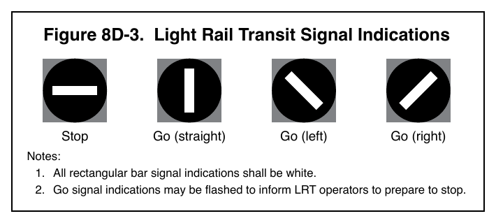
Go (straight) Go (left) Go (right) Notes:
- 1. All rectangular bar signal indications shall be white.
- 2. Go signal indications may be flashed to inform LRT operators to prepare to stop.
Option
07. If used, individual LRT signal sections may be displayed to form clustered signal faces or multiple LRT signal indications may be displayed in an individual housing.
Guidance
08. LRT signal faces should be located at least 3 feet from the nearest highway traffic signal face for the same approach measured either horizontally perpendicular to the approach between the centers of the signal faces or vertically from the center of the lowest signal indication of the top signal face to the center of the highest signal indication of the bottom signal face.
Support
09. Section 4F.18 contains information about the use of the LRT signal indications shown in Figure 8D-3 for the control of exclusive bus movements at “queue jumper lanes” and for the control of exclusive bus rapid transit movements on mixed-use alignments.