Chapter 8C. Markings¶
§8C.01 Purpose and Application¶
Support
01. Passive traffic control systems, consisting of signs and pavement markings only, identify and direct attention to the location of a grade crossing and advise road users to reduce their speed or stop at the grade crossing as necessary in order to yield to any rail traffic occupying, or approaching and in proximity to, the grade crossing.
02. Signs and pavement markings regulate, warn, and guide the road users so that they, as well as LRT vehicle operators on mixed-use alignments, can take appropriate action when approaching a grade crossing.
03. Unless otherwise provided in this Chapter, the provisions of Part 3 are applicable to the design and location of pavement markings at grade crossings.
§8C.02 Grade Crossing Pavement Markings¶
Standard
01. On paved roadways, grade crossing pavement markings shall consist of an X, the letters RR, a no-passing zone marking (on two-lane, two-way highways with center line markings in compliance with Section 3B.01), and certain transverse lines as shown with detailed dimensions in Figures 8C-1 and 8C-2.
02. Except as provided in Paragraphs 3 and 4 of this Section, grade crossing pavement markings shall be placed in each approach lane on all paved approaches to highway-rail grade crossings where signals or automatic gates are located, and at all other grade crossings where the posted or statutory highway speed is 40 mph or higher.
03. Grade crossing pavement markings shall not be required at highway-rail grade crossings where the posted or statutory highway speed is less than 40 mph if the Diagnostic Team determines that other installed devices provide suitable warning and control.
04. Grade crossing pavement markings shall not be required at highway-rail grade crossings in urban areas if the Diagnostic Team determines that other installed devices provide suitable warning and control.
05. Grade crossing pavement markings shall be placed in each approach lane on all paved approaches to highway-LRT grade crossings where a Crossbuck sign is placed at the grade crossing.
06. If grade crossing pavement markings are used on a multi-lane approach to a grade crossing, identical markings shall be placed in each approach lane that crosses the tracks.
07. All grade crossing pavement markings shall be retroreflective white. All other markings shall be in accordance with Part 3.
Guidance
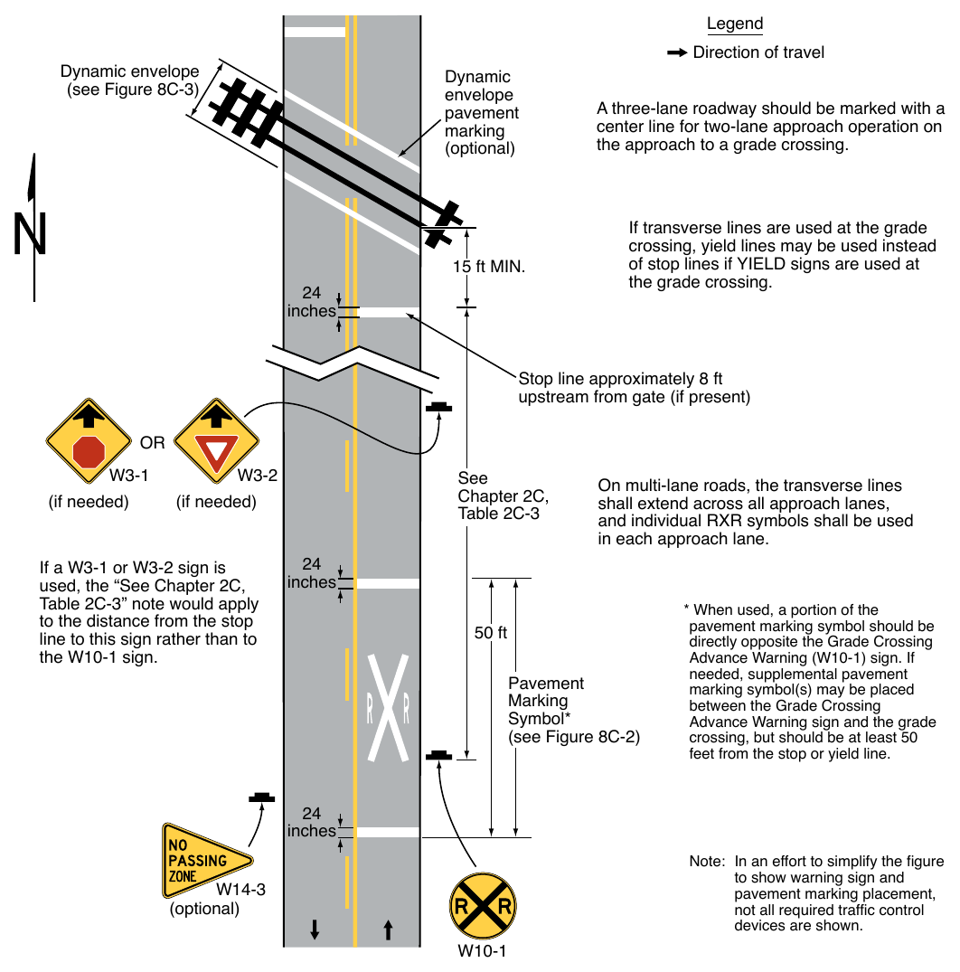
08. Where grade crossing pavement markings are used, a portion of the X symbol should be directly opposite the Grade Crossing Advance Warning sign.
Option
09. Where determined by the Diagnostic Team, supplemental pavement marking symbol(s) may be placed between the Grade Crossing Advance Warning sign and the grade crossing.
Guidance
10. If supplemental pavement marking symbol(s) are placed between the Grade Crossing Advance Warning sign and the grade crossing, the downstream transverse line should be at least 50 feet upstream from the stop or yield line at the grade crossing.
§8C.03 Stop and Yield Lines¶
Guidance
01. On paved roadway approaches to passive grade crossings where a STOP sign is installed in conjunction with the Crossbuck sign, a stop line should be installed to indicate the point behind which motor vehicles are required to stop or as near to that point as practicable.
Option
02. On paved roadway approaches to passive grade crossings where a YIELD sign is installed in conjunction with the Crossbuck sign, a yield line (see Section 3B.19) or a stop line may be installed to indicate the point behind which motor vehicles are required to yield or stop or as near to that point as practicable.
(see Figure 8C-3) Dynamic envelope pavement marking (optional)
24. inches 15 ft MIN. Direction of travel A three-lane roadway should be marked with a center line for two-lane approach operation on the approach to a grade crossing. If transverse lines are used at the grade crossing, yield lines may be used instead of stop lines if YIELD signs are used at the grade crossing. Stop line approximately 8 ft upstream from gate (if present) (if needed) See Chapter 2C, Table 2C-3 (if needed) If a W3-1 or W3-2 sign is used, the “See Chapter 2C, Table 2C-3” note would apply to the distance from the stop line to this sign rather than to the W10-1 sign.
24. inches On multi-lane roads, the transverse lines shall extend across all approach lanes, and individual RXR symbols shall be used in each approach lane. 50 ft Pavement Marking Symbol* (see Figure 8C-2) pavement marking symbol should be directly opposite the Grade Crossing Advance Warning (W10-1) sign. If needed, supplemental pavement marking symbol(s) may be placed between the Grade Crossing Advance Warning sign and the grade crossing, but should be at least 50 feet from the stop or yield line.
24. inches Note: In an effort to simplify the figure to show warning sign and pavement marking placement, not all required traffic control devices are shown. (optional)
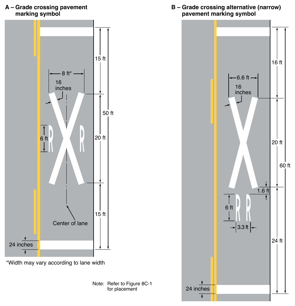
B – Grade crossing alternative (narrow) pavement marking symbol 15 ft 16 ft 8 ft* 6.6 ft
16. inches 50 ft 20 ft 6 ft 20 ft 60 ft 1.6 ft 6 ft 15 ft Center of lane 3.3 ft 24 ft 24 inches *Width may vary according to lane width Note: Refer to Figure 8C-1 for placement 24 inches
Guidance
03. If a yield line (see Figure 3B-16) or stop line is used at a passive grade crossing, it should be a transverse line at a right angle to the traveled way and should be placed no closer than 15 feet in advance of the nearest rail.
Standard
04. On paved roadways at grade crossings that are equipped with active control devices such as flashing-light signals, automatic gates, or traffic control signals, a stop line (see Section 3B.19) shall be installed to indicate the point behind which motor vehicles are or might be required to stop.
Guidance
05. If a stop line is used at an active grade crossing where road users are controlled by flashing-light signals, it should be a transverse line at a right angle to the traveled way and should be placed approximately 8 feet in advance of the flashing-light signals or automatic gate (if present), whichever is farther from the track(s), but no closer than 15 feet in advance of the nearest rail (see Figure 8C-1).
06. If a stop line is used at an active grade crossing where road users are controlled by a traffic control signal, it should be a transverse line at a right angle to the traveled way and should be placed no closer than 15 feet in advance of the nearest rail.
Standard
07. If a stop line is used at an active grade crossing where road users are controlled by a traffic control signal, it shall be placed such that the lateral and longitudinal positions of the signal faces for the approach comply with the provisions of Sections 4D.07 and 4D.08.
§8C.04 Lane-Use Arrow Markings¶
Standard
01. Lane-use arrow markings (see Section 3B.23) that indicate that a turning movement must be made or is permitted to be made from a lane that crosses a grade crossing shall not be placed between the stop line for the grade crossing and the track(s).
Guidance
02. Lane-use arrow markings that indicate that a turning movement must be made or is permitted to be made from a lane that crosses a grade crossing should not be placed less than 100 feet upstream from the stop line for the grade crossing or less than 20 feet beyond the farthest rail.
§8C.05 Edge Lines, Lane Lines, Center Lines, Raised Pavement Markers, and Tubular Markers¶
Guidance
01. Except as provided in Paragraphs 3 through 5 of this Section, if edge lines (see Section 3B.09), lane lines (see Section 3B.06), or center lines (see Section 3B.01) are used on an approach to a grade crossing, the edge lines, lane lines, and center lines should extend up to and across the grade crossing to reduce the likelihood that road users might inadvertently turn into the track area.
02. If crossing surface maintenance or highway approach maintenance is performed that alters the markings, the removal or replacement of the markings, raised pavement markers, and/or tubular markers should be coordinated with the road authority and the railroad company or transit agency.
Option
03. Edge lines, lane lines, and center lines may be omitted on or between the rails to conform to the requirements of the railroad company and/or transit agency.
04. Edge lines, lane lines, and center lines may be omitted on or between the rails where the highway profile is sufficiently abrupt to create a hang-up situation for pavement marking equipment with low ground clearance.
05. The edge lines, lane lines, and center lines may be omitted from the highway surface at a grade crossing if the surface cannot retain the application of the edge line, lane line, or center line marking.
06. If recommended by a Diagnostic Team, raised pavement markers (see Section 3B.16) may be used to supplement the edge lines, lane lines, or center lines that extend up to and across the grade crossing.
07. If recommended by a Diagnostic Team, tubular markers (see Section 3I.02) may be used to supplement the edge lines that extend up to and across the grade crossing.
Guidance
08. Tubular markers should be installed in accordance with the clearance requirements of the railroad company and/or transit agency.
Standard
09. The color under both daytime and nighttime conditions of raised pavement markers or tubular markers that are used at a grade crossing shall be the same color as the edge line, lane line, or center line that they supplement.
§8C.06 Dynamic Envelope and Do Not Block Pavement Markings¶
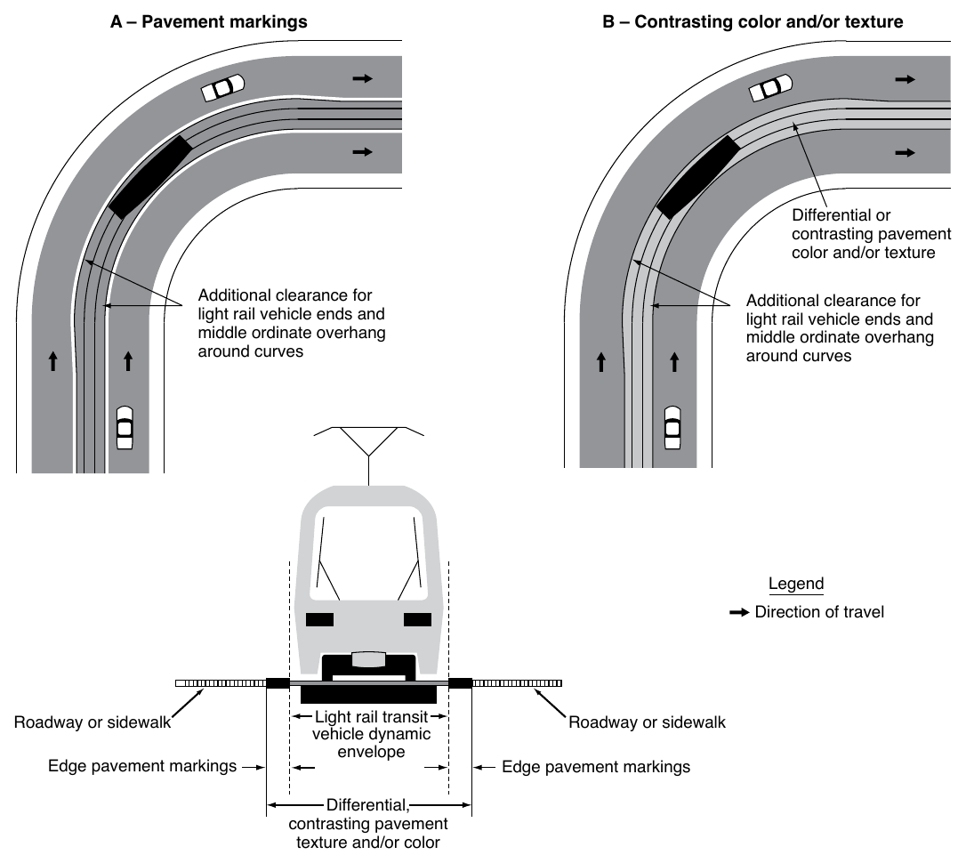
Option
01. Dynamic envelope markings may be installed at a grade crossing to mark the edges of the train dynamic envelope.
Standard
02. If used, pavement markings for indicating the dynamic envelope shall comply with the provisions of Part 3 and shall be a solid white line not less than 4 inches or greater than 24 inches in width.
Option
03. Contrasting pavement color (see Section 3A.03 and Chapter 3H) and/or contrasting pavement texture may be used alone or in combination with pavement markings to indicate the dynamic envelope.
Guidance
04. If a solid white line is used to convey the dynamic envelope, the line should be placed completely outside of the dynamic envelope. If used, dynamic envelope pavement markings should be placed parallel to the nearest rail in accordance with the railroad company or transit agency requirements. If used, dynamic envelope pavement markings should extend across the roadway as shown in Figure 8C-3. Dynamic envelope pavement markings should not be placed perpendicular to the roadway at skewed grade crossings.
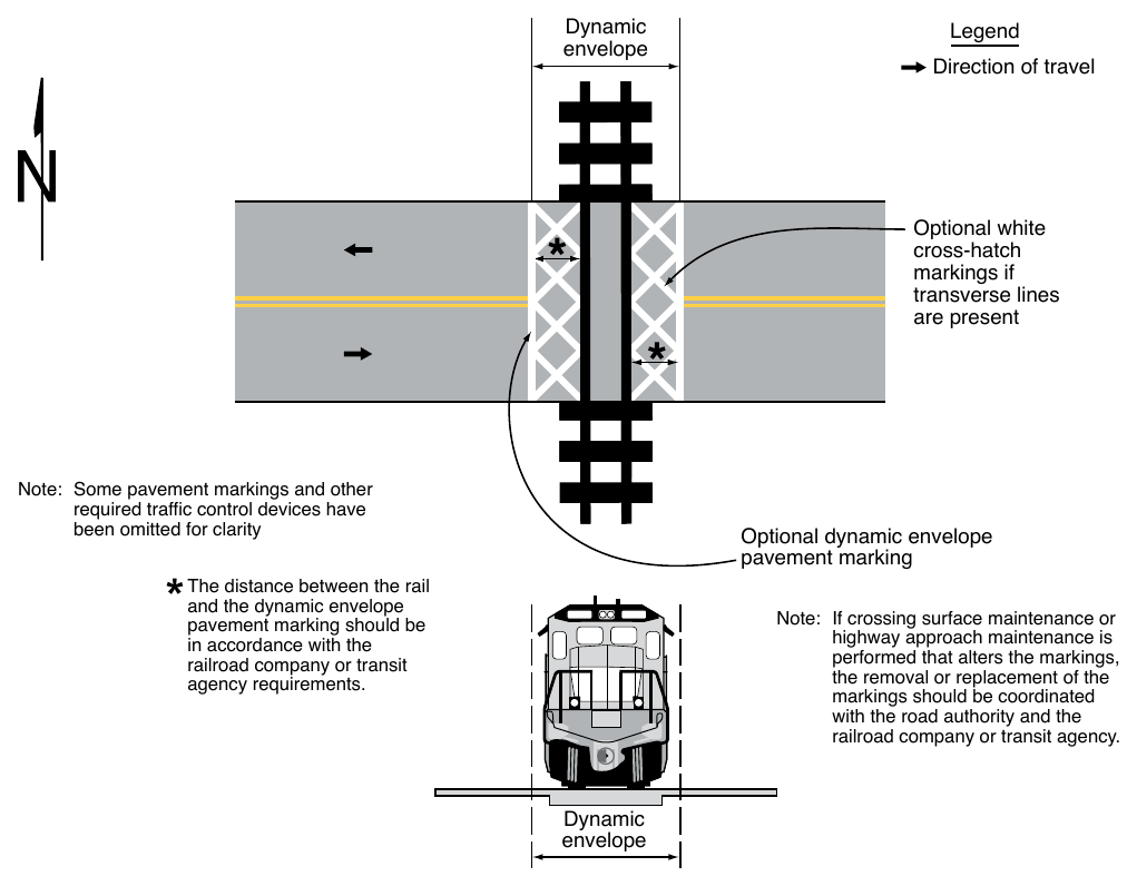
Note: Some pavement markings and other required traffic control devices have been omitted for clarity Optional dynamic envelope pavement marking The distance between the rail and the dynamic envelope pavement marking should be in accordance with the railroad company or transit agency requirements. Note: If crossing surface maintenance or highway approach maintenance is performed that alters the markings, the removal or replacement of the markings should be coordinated with the road authority and the railroad company or transit agency. Dynamic envelope
Option
05. If solid white lines are used to indicate the dynamic envelope, white cross-hatching lines (see Figure 8C-3) may also be placed on the highway pavement within the dynamic envelope as a supplement to, but not as a substitute for, the solid white lines. White cross-hatching lines (see Section 3B.26) may also be placed on the pavement to mark areas adjacent to the dynamic envelope where vehicles are not intended to stop or stand as shown in Figure 8C-4.
06. In semi-exclusive LRT alignments, the dynamic envelope markings may be along the LRT trackway between intersections where the trackway is immediately adjacent to travel lanes and no physical barrier is present.
07. In mixed-use LRT alignments, the dynamic envelope markings may be continuous between intersections (see Figure 8C-5).
08. In mixed-use LRT alignments, pavement markings for adjacent travel or parking lanes may be used instead of dynamic envelope markings if the lines are outside the dynamic envelope.
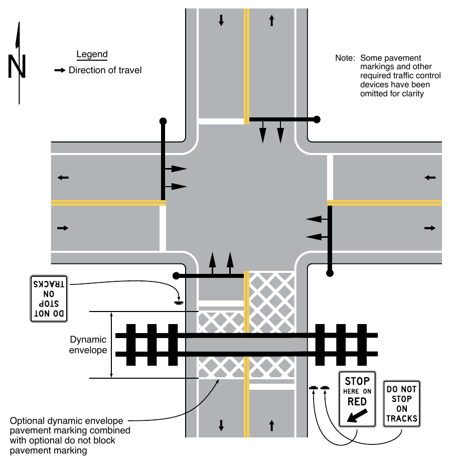
Note: Some pavement markings and other required traffic control devices have been omitted for clarity Dynamic envelope Optional dynamic envelope pavement marking combined with optional do not block pavement marking