Chapter 4E. Traffic Control Signal Indications¶
§4E.01 Signal Indications – Design, Illumination, Color, and Shape¶
Standard
01. The illuminated part of each signal indication shall be circular or arrow, except those used for bicycle symbol signal indications, pedestrian signal heads, light rail transit signal indications, and lane-use control signals.
02. Letters or numbers (including those associated with countdown displays) shall not be displayed as part of a vehicular signal indication.
03. Strobes shall not be used within or adjacent to any signal indication.
04. Except for the flashing vehicular and pedestrian signal indications and the distinctive indications for emergency-vehicle preemption (see Section 4F.19) that are expressly allowed by the provisions of this Part, flashing displays shall not be used within or adjacent to any signal indications.
05. Each circular signal indication shall emit a single color: red, yellow, or green.
06. Except as provided in Paragraph 7 of this Section, each arrow signal indication shall emit a single color: red, yellow, or green.
Option
07. A bimodal signal section that is capable of alternating between the display of a GREEN ARROW signal indication and the display of a YELLOW ARROW signal indication, both pointing in the same direction, may be used provided that both colors are never displayed simultaneously.
Standard
08. The arrow, which shall show only one direction, shall be the only illuminated part of an arrow signal indication.
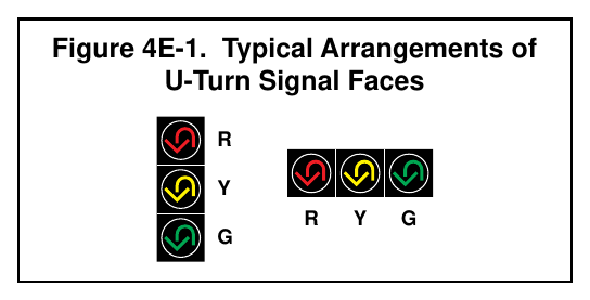
09. Arrows shall be pointed:
- A. Vertically upward to indicate a straight-through movement,
- B. Horizontally in the direction of the turn to indicate a turn at approximately or greater than a right angle,
- C. Upward with a slope at an angle approximately equal to that of the turn if the angle of the turn is substantially less than a right angle, or
- D. In a manner that directs the driver through the turn if a U-turn arrow is used (see Figure 4E-1).
10. Except as provided in Paragraph 11 of this Section, the requirements of Chapters 1 and 2 of the publication entitled “Equipment and Materials Standards of the Institute of Transportation Engineers” that pertain to the aspects of the signal head design that affect the display of the signal indications shall be met for signal optical units that use incandescent lamps within optical assemblies that include lenses. Except as provided in Paragraph 11 of this Section, the requirements of the Institute of Transportation Engineers’ publications entitled “Vehicle Traffic Control Signal Heads: Light Emitting Diode (LED) Circular Signal Supplement,” 2005, ITE, and “Vehicle Traffic Control Signal Heads: Light Emitting Diode (LED) Vehicle Arrow Traffic Signal Supplement,” 2008, ITE, that pertain to the aspects of the signal head design that affect the display of the signal indications shall be met for light-emitting diode (LED) traffic signal modules.
Guidance
11. The intensity and distribution of light from each illuminated signal lens or LED signal module should comply with the publications specified in Paragraph 10 of this Section, as appropriate.
Support
12. References to signal lenses in this Section are not intended to limit signal optical units to incandescent lamps within optical assemblies that include lenses. Research has resulted in signal optical units that are not lenses, such as, but not limited to, light-emitting diode (LED) traffic signal modules. Some units are practical for all signal indications, and some are practical for specific types such as visibility-limited signal indications.
Guidance
13. If a signal indication is so bright that it causes excessive glare during nighttime conditions, some form of automatic dimming should be used to reduce the brilliance of the signal indication.
§4E.02 Size of Vehicular Signal Indications¶
Standard
01. There shall be three nominal diameter sizes for vehicular signal indications: 4 inches, 8 inches, and 12 inches.
02. Four-inch signal indications shall only be used for bicycle signal faces per Section 4H.07.
03. Twelve-inch signal indications shall be used for all arrow signal indications.
04. Except as provided in Paragraph 5 of this Section, 12-inch signal indications shall be used for all circular signal indications in all new signal faces.
Option
05. Eight-inch circular signal indications may be used in new signal faces only for:
- A. The green or flashing yellow signal indications in an emergency-vehicle traffic control signal (see Section 4M.02);
- B. The circular indications in signal faces controlling the approach to the downstream location where two adjacent signalized locations are close to each other and it is impractical because of factors such as high approach speeds, horizontal or vertical curves, or other geometric factors to install visibility-limited signal faces for the downstream approach;
- C. The circular indications in a signal face that is located less than 120 feet from the stop line on a roadway with a posted or statutory speed limit or operating speed of 30 mph or less;
- D. The circular indications in a supplemental near-side signal face;
- E. The circular indications in a supplemental signal face installed for the sole purpose of controlling pedestrian movements rather than vehicular movements; and
- F. The circular indications in a flashing beacon (see Chapter 4S).
06. Different sizes of signal indications may be used in the same signal face or signal head, provided that the signal face or signal head complies with the requirements contained in Paragraphs 3 through 5 of this Section.
§4E.03 Positions of Signal Indications within a Signal Face – General¶
Support
01. Standardization of the number and arrangements of signal sections in vehicular traffic control signal faces enables road users who are color vision deficient to identify the illuminated color by its position relative to other signal sections.
Standard
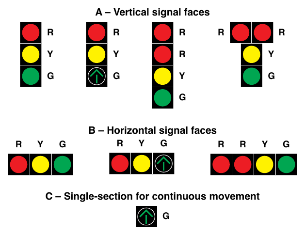
02. Unless otherwise provided in this Manual for a particular application, each signal face at a signalized location shall have three, four, or five signal sections. Unless otherwise provided in this Manual for a particular application, if a vertical signal face includes a cluster (see Section 4E.04), the signal face shall have at least three vertical positions.
03. A single-section signal face shall be permitted at a traffic control signal if it consists of a continuously displayed GREEN ARROW signal indication that is being used to indicate a continuous movement.
04. The signal sections in a signal face shall be arranged in a vertical or horizontal straight line, except as otherwise provided in Section 4E.04.
05. The arrangement of adjacent signal sections in a signal face shall follow the relative positions listed in Sections 4E.04 or 4E.05, as applicable.
06. If a signal section that displays a CIRCULAR YELLOW signal indication is used, it shall be located between the signal section that displays the red signal indication and all other signal sections.
07. If a U-turn arrow signal section is used in a signal face for a U-turn to the left, its position in the signal face shall be the same as stated in Sections 4E.04 and 4E.05 for a left-turn arrow signal section of the same color. If a U-turn arrow signal section is used in a signal face for a U-turn to the right, its position in the signal face shall be the same as stated in Sections 4E.04 and 4E.05 for a right-turn arrow signal section of the same color.
08. A U-turn arrow signal indication pointing to the left shall not be used in a signal face that also contains a left-turn arrow signal indication. A U-turn arrow signal indication pointing to the right shall not be used in a signal face that also contains a right-turn arrow signal indication.
Option
09. Within a signal face, two identical CIRCULAR RED or RED ARROW signal indications may be displayed immediately horizontally adjacent or immediately vertically adjacent to each other in a vertical signal face (see Drawing A in Figure 4E-2) or immediately horizontally adjacent to each other in a horizontal signal face (see Drawing B in Figure 4E-2) for emphasis.
10. Horizontally-arranged and vertically-arranged signal faces may be used on the same approach provided they are separated to meet the lateral separation spacing required in Section 4D.07.
Support
11. Figure 4E-2 illustrates some of the typical arrangements of signal sections in signal faces that do not control separate turning movements. Figures 4F-1 through 4F-7 illustrate the typical arrangements of signal sections in left-turn signal faces. Figures 4F-8 through 4F-14 illustrate the typical arrangements of signal sections in right-turn signal faces.
§4E.04 Positions of Signal Indications within a Vertical Signal Face¶
Standard
01. In each vertically-arranged signal face, all signal sections that display red signal indications shall be located above all signal sections that display yellow and green signal indications.
02. In vertically-arranged signal faces, each signal section that displays a YELLOW ARROW signal indication shall be located above the signal section that displays the GREEN ARROW signal indication to which it applies.
03. The relative positions of signal sections in a vertically-arranged signal face, from top to bottom, shall be as follows: Steady and/or flashing left-turn RED ARROW Steady and/or flashing right-turn RED ARROW Straight-through GREEN ARROW Steady left-turn YELLOW ARROW Flashing left-turn YELLOW ARROW Left-turn GREEN ARROW Steady right-turn YELLOW ARROW Flashing right-turn YELLOW ARROW Right-turn GREEN ARROW
04. If a bimodal signal section (see Section 4E.01) is used in a vertically-arranged signal face, the bimodal signal section shall occupy the same position relative to the other sections as the signal section that displays the GREEN ARROW signal indication in a vertically-arranged signal face would occupy.
Option
05. In a vertically-arranged signal face, signal sections that display signal indications of the same color may be arranged horizontally adjacent to each other at right angles to the basic straight line arrangement to form a clustered signal face (see Figures 4E-2, 4F-3, 4F-4, 4F-6, 4F-10, 4F-11, 4F-13, and 4F-15).
Standard
06. Such clusters shall be limited to the following:
- A. Two identical signal sections,
- B. Two or three different signal sections that display signal indications of the same color, or
- C. For only the specific case described in Section 4F.16 (see Drawing B in Figure 4F-15), two signal sections, one of which displays a GREEN ARROW signal indication and the other of which displays a flashing YELLOW ARROW signal indication.
07. Except as otherwise provided in Sections 4F.04, 4F.08, 4F.11, and 4F.15 for a three-section separate turn signal face with a bimodal signal section that displays a flashing YELLOW ARROW signal indication, the signal section that displays a flashing yellow signal indication during steady mode operation:
- A. Shall not be placed in the same vertical position as the signal section that displays a steady yellow signal indication, and
- B. Shall be placed below the signal section that displays a steady yellow signal indication.
Support
08. Sections 4J.02 and 4N.02 contain exceptions to the provisions of this Section that are applicable to hybrid beacons.
§4E.05 Positions of Signal Indications within a Horizontal Signal Face¶
Standard
01. In each horizontally-arranged signal face, all signal sections that display red signal indications shall be located to the left of all signal sections that display yellow and green signal indications.
02. In horizontally-arranged signal faces, each signal section that displays a YELLOW ARROW signal indication shall be located to the left of the signal section that displays the GREEN ARROW signal indication to which it applies.
03. The relative positions of signal sections in a horizontally-arranged signal face, from left to right, shall be as follows: Steady and/or flashing left-turn RED ARROW Steady and/or flashing right-turn RED ARROW Steady left-turn YELLOW ARROW Flashing left-turn YELLOW ARROW Left-turn GREEN ARROW Straight-through GREEN ARROW Steady right-turn YELLOW ARROW Flashing right-turn YELLOW ARROW Right-turn GREEN ARROW
04. If a bimodal signal section (see Section 4E.01) is used in a horizontally-arranged signal face, the signal section that displays the dual left-turn arrow signal indication shall be located immediately to the right of the signal section that displays the CIRCULAR YELLOW signal indication, the signal section that displays the straight-through GREEN ARROW signal indication shall be located immediately to the right of the signal section that displays the CIRCULAR GREEN signal indication, and the signal section that displays the dual right-turn arrow signal indication shall be located to the right of all other signal sections.
05. Except as otherwise provided in Sections 4F.04, 4F.08, 4F.11, and 4F.15 for a three-section separate turn signal face with a flashing YELLOW ARROW signal indication, the signal section that displays a flashing yellow signal indication during steady mode operation:
- A. Shall not be placed in the same horizontal position as the signal section that displays a steady yellow signal indication, and
- B. Shall be placed to the right of the signal section that displays a steady yellow signal indication.