Chapter 9E. Markings¶
§9E.01 Bicycle Lanes¶
Support
01. Pavement markings designate that portion of the roadway for preferential use by bicyclists. Markings inform all road users of the restricted nature of the bicycle lane.
Standard
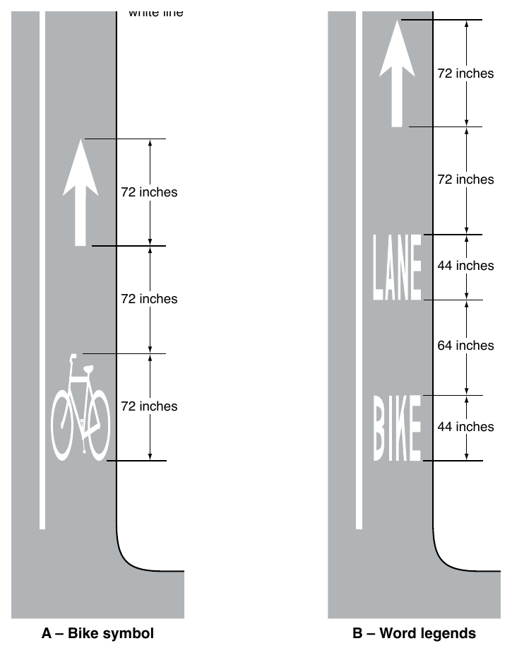
02. Longitudinal pavement markings and bicycle lane symbol or word markings (see Figure 9E-1) shall be used to define bicycle lanes.
Guidance
03. The first symbol or word marking in a bicycle lane should be placed at the beginning of the bicycle lane and downstream symbol or word markings should be placed after major intersections. Additional symbol or word markings should be placed at periodic intervals along the bicycle lane based on engineering judgment.
Option
04. An arrow marking (see Figure 9E-1) may be used in conjunction with the bicycle lane symbol or word marking, placed downstream from the symbol or word marking.
05. Where the bicycle lane symbols or word markings are used, Bicycle Lane signs (see Section 9B.04) may also be used, but not necessarily adjacent to every set of pavement markings in order to avoid overuse of the signs.
Support
06. Section 3H.06 contains information on green-colored pavement for use in bicycle lanes.
Standard
07. The bicycle symbol or BIKE LANE pavement word marking and the pavement marking arrow shall not be used in a shoulder.
08. A portion of the roadway shall not be established as both a shoulder and a bicycle lane.
Support
09. Where a shoulder is provided or is of sufficient width to meet the expectation of a highway user in that it can function as a space for emergency, enforcement, or maintenance activities, or avoidance or recovery maneuvers, Section 9B.16 contains information regarding the Bicycles Use Shoulder Only sign that can be used to denote locations on a freeway or expressway where bicycles are permitted on an available and usable shoulder.
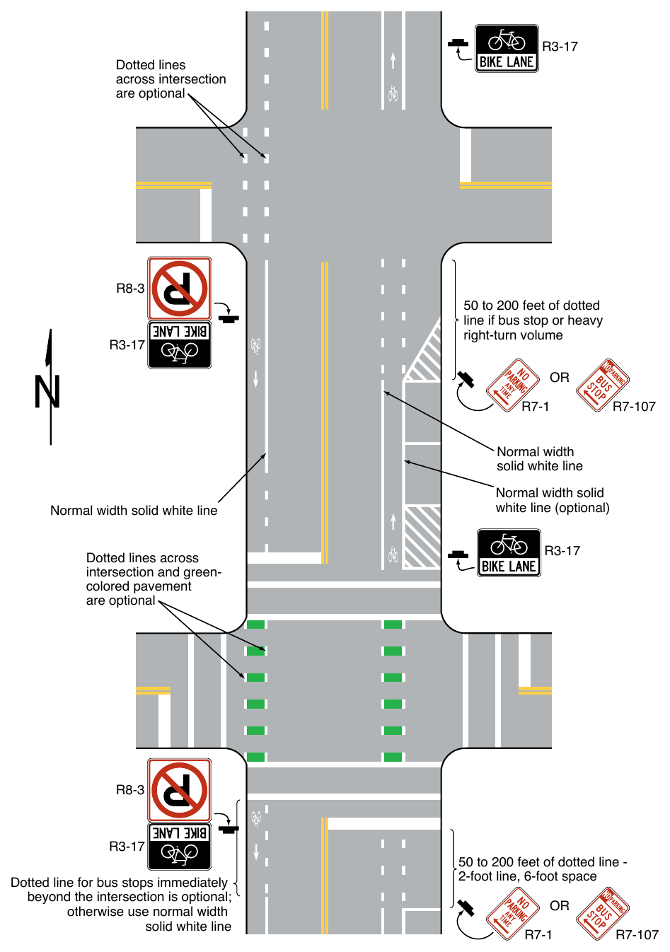
10. Examples of pavement markings for bicycle lanes on a two-way street are shown in Figure 9E-2.
§9E.02 Bicycle Lanes at Intersection Approaches¶
Standard
01. Except as provided in Paragraph 2 of this Section, a through bicycle lane shall not be positioned to the right of a right turn only lane or to the left of a left turn only lane.
Option
02. A through bicycle lane may be positioned to the right of a right turn only lane or to the left of a left turn only lane provided that the bicycle lane is controlled by a traffic signal that displays bicycle signal indications (see Chapter 4H).
Support
03. Unless controlled by a bicycle signal indication, a bicyclist continuing straight through an intersection from the right of a right turn only lane or from the left of a left turn only lane would be inconsistent with normal traffic behavior and would violate the expectations of right-turning or left-turning motorists.
Guidance
04. When the right (left) through lane is dropped to become a mandatory right-turn (left-turn) lane, the bicycle lane markings should stop at least 100 feet before the beginning of the right-turn (left-turn) lane. Through bicycle lane markings should resume to the left (right) of the mandatory right-turn (left-turn) lane.
05. Except as provided in Paragraph 2 of this Section, an optional through-right (through-left) turn lane next to a mandatory right-turn (left-turn) lane should not be used where there is a through bicycle lane.
Standard
06. A bicycle lane located on an intersection approach between general-purpose lanes for motor vehicle movements shall be marked with at least one bicycle symbol or word marking and at least one arrow pavement marking as provided in Paragraph 4 of Section 9E.01.
07. A bicycle lane shall not be marked within a general-purpose lane, either with dotted or any other line markings.
Option
08. Where there is insufficient width in the roadway to include both a bicycle lane and a general-purpose turn lane, bicycle travel may be accommodated within the turn lane or general-purpose lane using shared-lane markings.
Standard
09. Where a general-purpose turn lane is controlled by a traffic control signal, through bicycle movements shall not be accommodated in the turn lane unless the turning movement is always permitted to proceed simultaneously with the adjacent through movement.
Support
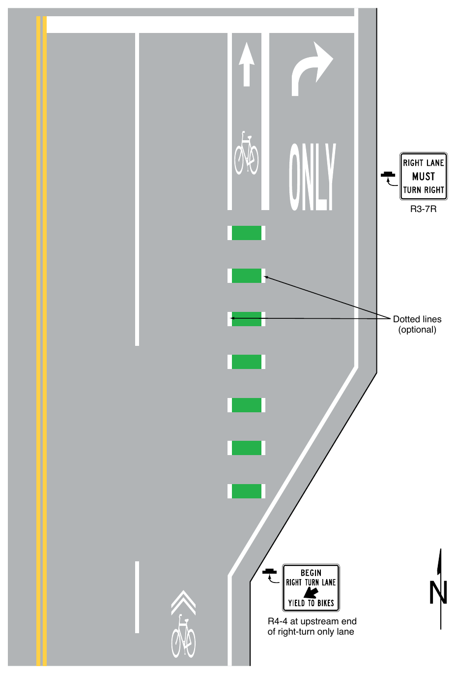
10. Examples of bicycle lane markings on approaches to intersections are shown in Figures 9E-3, 9E-4, and 9E-9.
Guidance
11. The longitudinal line defining a bicycle lane should be dotted on approaches to intersections where turning vehicles are permitted to cross the path of through-moving bicycles (see Figure 9D-7).
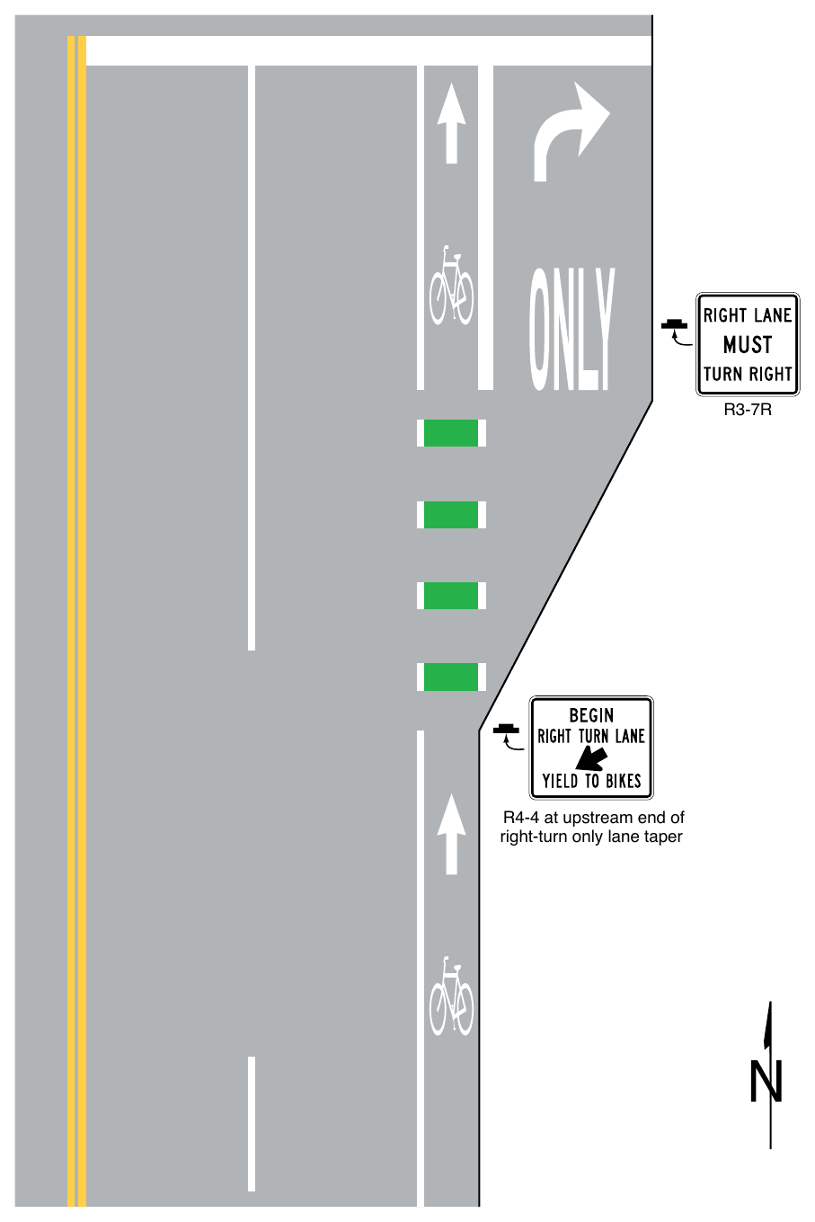
Signs shown: R3-7R, R4-4
(Sheet 1 of 3) R4-4 at upstream end of right-turn only lane taper
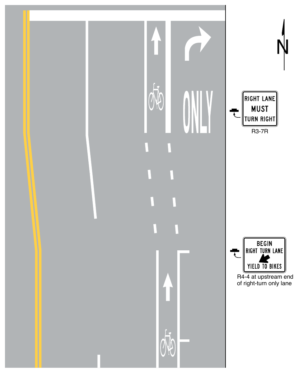
Signs shown: R3-7R, R4-4
(Sheet 2 of 3) R4-4 at upstream end of right-turn only lane
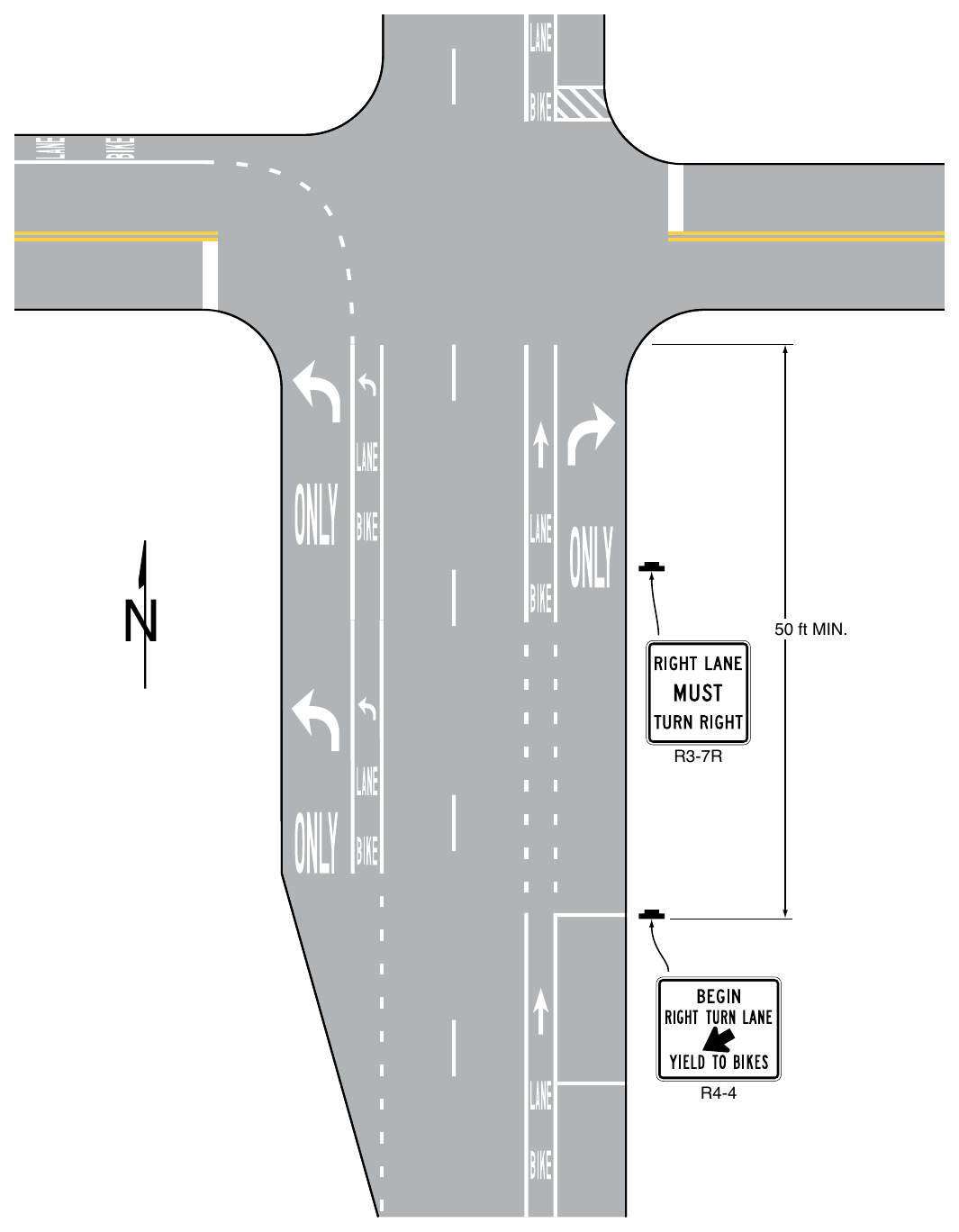
Signs shown: R3-7R, R4-4
(Sheet 3 of 3) 50 ft MIN.
Signs shown: R3-7R, R4-4
Support
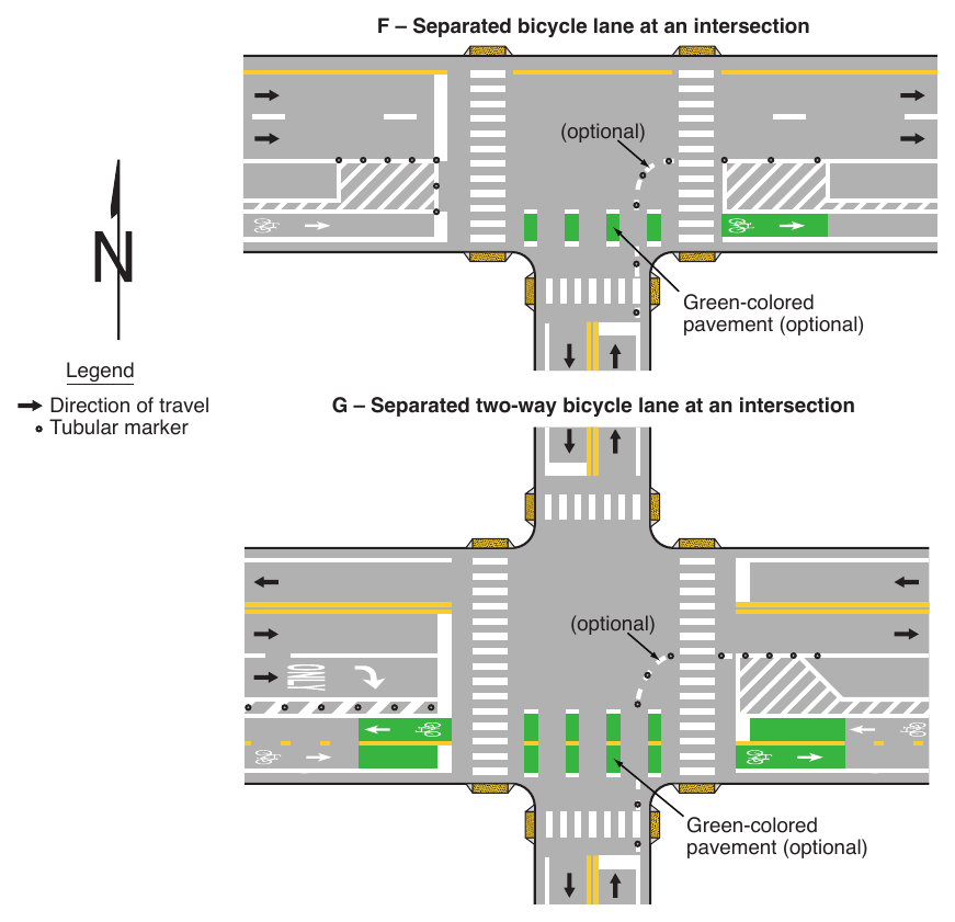
12. Buffer-separated and separated bicycle lanes require additional considerations at intersections, including sight distances for bicycles and other road users, user expectations, and intersection geometry.
Option
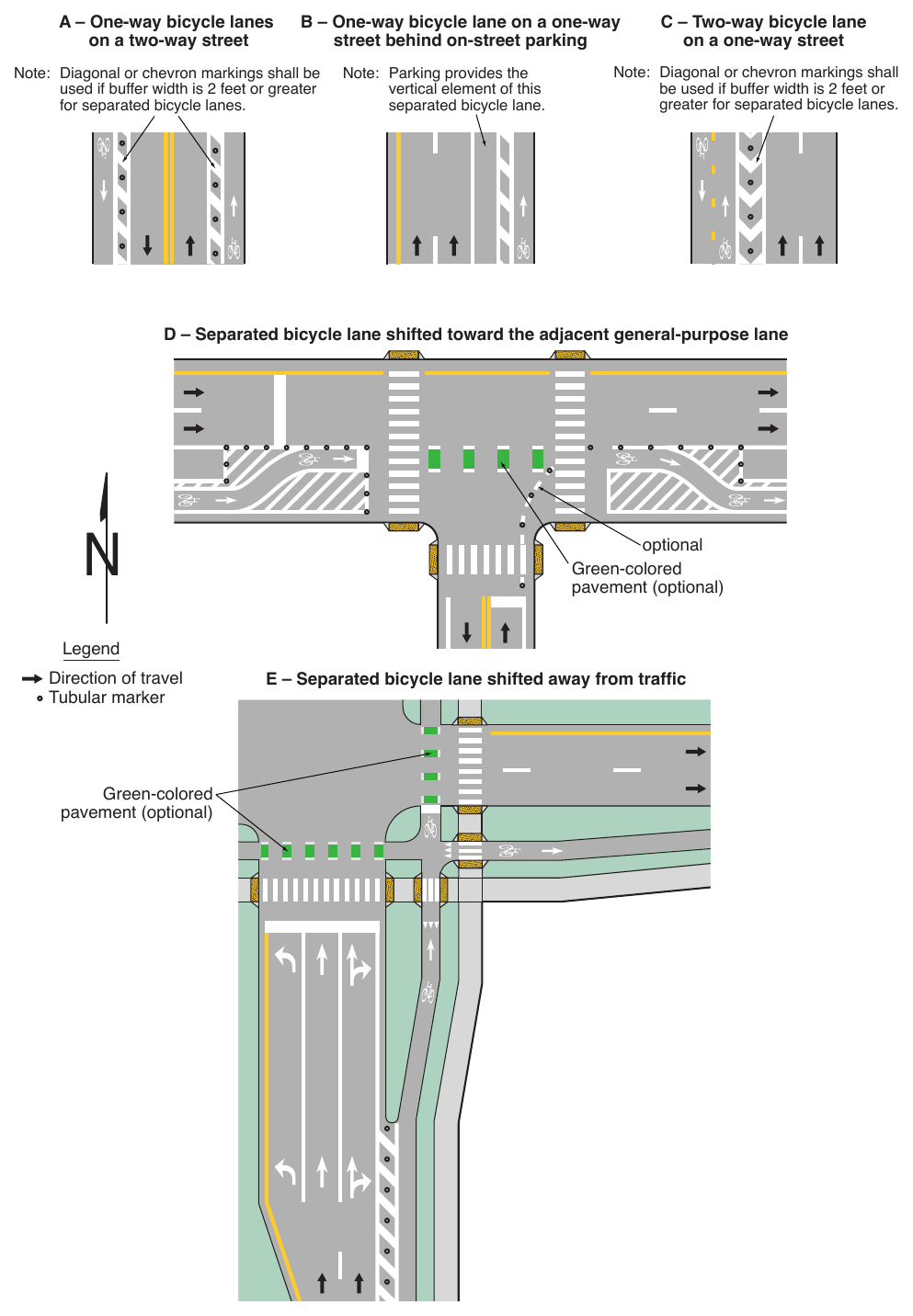
13. A buffer-separated or separated bicycle lane may be shifted closer to, or farther away from the adjacent general-purpose lane depending upon site-specific conditions (see Drawings D and E in Figure 9E-7).
Support
14. A buffer-separated or separated bicycle lane shifted away from the adjacent general-purpose lane at an intersection can create space for a motor vehicle to queue between the general-purpose lane and the extension of the bicycle lane. This design can also improve the safety and comfort of bicyclists by reducing the speed of turning motor vehicles, improving sightlines, and creating additional buffer space prior to the conflict point with turning motor vehicles.
15. The purpose of shifting a buffer-separated or separated bicycle lane away from the adjacent general-purpose lane is to allow the driver of a turning vehicle to undertake the tasks of turning and scanning for bicycle cross traffic in isolation versus simultaneously. Sufficient sight distance for both drivers and bicyclists is important in this design (see Drawing E in Figure 9E-7).
16. The purpose of shifting a buffer-separated or separated bicycle lane toward the adjacent general-purpose lane is to improve the visibility of bicyclists to the adjacent traffic and avoid conflicts between turning motor vehicles and bicyclists (see Drawing D in Figure 9E-7).
17. Staggering stop lines (see Section 3B.19) so that general-purpose lanes stop further in advance from the intersection than the bicycle lane can improve the visibility of bicyclists for drivers of turning vehicles (see Drawing D in Figure 9E-7).
Option
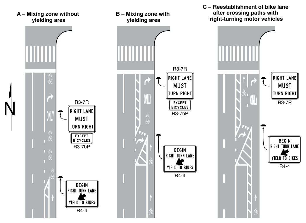
18. Where a general-purpose mandatory turn lane is provided at an intersection and the approach also includes a separated or buffer-separated bicycle lane, a mixing zone may be established to allow general-purpose turning traffic to share the roadway space with bicyclists (see Figure 9E-5).
Standard
19. Mixing zones shall be used only where the bicycle lane is one-way in the same direction of travel as the adjacent general-purpose lane.
20. Mixing zones with a yielding area shall have yield markings indicating where general-purpose traffic entering the shared space shall yield to bicyclists.
21. Where a mixing zone continues to the intersection itself sharing space between bicyclists and general-purpose turning traffic, shared-lane markings and turn arrows shall be provided in the lane.
Support
22. Mixing zones require bicycles and general traffic to share space, interrupting a buffer-separated or separated bicycle lane where bicycle traffic is otherwise separated from general traffic. The preference is to provide a dedicated bicycle facility for the intersection approach; if that is not possible, the mixing zone needs to indicate that bicyclists and motorists are entering a shared condition.
Guidance
23. Where a mixing zone provides for the re-establishment of a bicycle lane after bicycles and general-purpose lanes cross paths, a buffered or physically-separated space should be provided between the bicycle lane and the adjacent general-purpose lane (see Drawing C in Figure 9E-5).
§9E.03 Extensions of Bicycle Lanes through Intersections¶
Support
01. Extensions of bicycle lanes through intersections can help identify the paths of bicyclists and guide them on movements that could be difficult to discern. Extensions of bicycle lanes through intersections also assist other road users of the intersection to identify where bicyclists are expected to operate and to recognize potentially unexpected conflict points.
02. The design, placement, and maintenance of bicycle lane extensions through intersections are important considerations, especially when contiguous to a crosswalk, to avoid potential confusion to pedestrians with vision disabilities.
03. The width and color of lane extension markings are discussed in Section 3B.11.
Option
04. The bicycle symbol, the arrow marking, pavement word markings, or a combination thereof may be used in bicycle lane extensions through intersections.
05. Green-colored pavement may be used in a bicycle lane extension in accordance with the provisions of Section 3H.06.
Standard
06. Shared-lane markings or chevron markings shall not be used in bicycle lanes or bicycle lane extensions (see Section 9E.09).
07. Extensions of bicycle lanes through intersections shall use dotted line patterns.
Support
08. Separated and buffer-separated bicycle lanes may have alignments that are not as obvious within an intersection as a standard bicycle lane, therefore additional conspicuity is important where these types of bicycle lanes cross intersections.
Guidance
09. Lane extension markings should be used to extend a buffer-separated or separated bicycle lane through intersections and driveways.
10. The extension of a bicycle lane through an intersection should use two lines defining both lateral limits of the bicycle lane.
Standard
11. Where the path of the bicycle lane through the intersection is contiguous to a crosswalk, two longitudinal dotted lines shall be provided to establish the lateral limits of the bicycle lane extension. The transverse line establishing one side of the crosswalk, or the limit of a high-visibility crosswalk pattern (see Section 3C.05) that does not employ a transverse line, shall not be used to demarcate one side of the bicycle lane extension.
§9E.04 Bicycle Lanes at Driveways¶
Support
01. The definition of an “Intersection” in Section 1C.02 contains information to determine if a driveway can be considered an intersection.
Option
02. Bicycle lanes may be continued through a driveway using solid or dotted longitudinal lines.
03. The bicycle symbol, the arrow marking, pavement word markings, or a combination thereof may be used in bicycle lane extensions through driveways.
04. Green-colored pavement (see Section 3H.06) may be used as a background to enhance the conspicuity of the bicycle symbol at driveways.
§9E.05 Bicycle Lanes at Circular Intersections¶
Standard
01. Bicycle lanes shall not be provided in the circulatory roadway of an unsignalized circular intersection that includes conflicts at entry or exit points (see Chapter 3D) except as provided in Paragraph 4 of this Section.
Guidance
02. Bicycle lane markings should stop at least 100 feet before the crosswalk, or if no crosswalk is provided, at least 100 feet before the yield line, or if no yield line is provided, then at least 100 feet before the edge of the circulatory roadway.
03. If used, bicycle crossings should be a minimum of 20 feet from the edge of the circulatory roadway.
Option
04. Separated bicycle lanes may be used in circular intersections.
Support
05. Separated bicycle lanes allow bicycles to navigate a circular intersection and its crossing points without merging into traffic and without dismounting and using a crosswalk at the intersection crossing point. This is beneficial at multi-lane and higher-speed circular intersections.
06. Section 9E.10 contains information on using shared-lane markings to facilitate the bicycle movement through a circular intersection.
07. The “Guide for the Development of Bicycle Facilities,” 2012 Fourth Edition, American Association of State Highway and Transportation Officials, contains information on designing for bicycles on the sidewalk in lieu of, or in addition to, using shared-lane markings in the circulatory roadway of the intersection.
08. The “Improving Intersections for Pedestrians and Bicyclists Informational Guide” (FHWA-SA-22-017), FHWA, contains information on incorporating separated bicycle lanes and other bicycle facilities into circular intersections.
§9E.06 Buffer-Separated Bicycle Lanes¶
Support
01. Buffer-separated bicycle lanes provide additional lateral separation between a bicycle lane and a general-purpose lane by a pattern of pavement markings without the presence of vertical elements. Providing a buffer space between a bicycle lane and a general-purpose lane creates more separation between motor vehicles and bicycles, can reduce vehicle encroachment into the bicycle lane, and can increase the comfort of bicyclists.
02. Providing a buffer space between a bicycle lane and a parking lane can reduce crashes involving bicycles and the opening of vehicle doors from the parking lane.
Standard
03. If used, and except as provided in Paragraph 5 of this Section, a buffer space shall be marked with a solid white line along both edges of the buffer space where crossing is discouraged.
Guidance
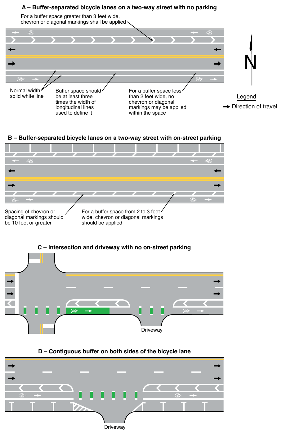
04. Engineering judgment should be used to establish intermittent breaks or interruptions in the buffer space, such as for driveways, transit stops, or on-street parallel parking lanes, in order to convey access points or an otherwise general legal movement to cross the buffer space (see Figure 9E-6).
Option
05. Buffer spaces may be established without specific longitudinal lines if contiguous facilities have longitudinal lines or other pavement markings themselves that, when installed, automatically demarcate the buffer space (see Drawing D in Figure 9E-6).
Standard
06. Except as provided in Paragraph 7 of this Section, a through buffer-separated bicycle lane shall not be positioned to the right of a mandatory right-turn lane or to the left of a mandatory left-turn lane.
Option
07. A buffer-separated bicycle lane may be placed to the right of a mandatory right-turn lane (or to the left of a mandatory left-turn lane) only if a bicycle signal face (see Section 4H.01) is used and the signal phasing and signing eliminates any potential conflicts between the bicycle movement and the turning movement.
Guidance
08. The width of the buffer space should be at least 3 times the width of the normal or wide longitudinal line used to mark the buffer space.
09. Where a buffer space is 2 to 3 feet wide, chevron or diagonal markings (see Section 3B.25) should be applied within the buffer space.
Option
10. Where a buffer space is less than 2 feet wide, diagonal markings or no markings at all in the buffer space may be applied within the buffer space.
Standard
11. If used, diagonal markings shall slant away from traffic in the adjacent travel lane for motorvehicle traffic.
Guidance
12. Where used, the spacing of chevrons or diagonal markings should be 10 feet or greater.
Support
13. Chevron and diagonal markings convey that the buffer space is not an additional bicycle lane or other travel lane open to traffic.
Standard
14. Where a buffer space is more than 3 feet wide, chevron or diagonal markings shall be applied within the buffer space.
Guidance
15. Lane extension markings should be used to extend a buffer-separated bicycle lane across intersections and driveways.
§9E.07 Separated Bicycle Lanes¶
Support
01. Separated bicycle lanes provide a physical separation between a general-purpose lane and a bicycle lane through the use of vertical objects or vertical separation between the general-purpose lane and bicycle lane. Providing a physical separation between a bicycle lane and a general-purpose lane can reduce vehicle encroachment into the bicycle lane beyond a marked buffer alone and can in some cases prevent that encroachment altogether.
02. Physical separation between general-purpose lanes and bicycle lanes introduces additional design considerations over buffer-separated bicycle lanes, including the awareness of a potentially unexpected conflict point for turning motor vehicles and the provision of adequate sight distance for all users at intersections and driveway crossings.
Option
03. Vertical elements used to provide physical separation between general-purpose lanes and bicycle lanes may include, but are not limited to, tubular markers, raised islands, or parked vehicles.
Support
04. Where on-street parking is provided adjacent to the buffer area of a separated bicycle lane, pedestrians will need to access those vehicles.
Guidance
05. BIKE LANE (R3-17) signs (see Figure 9B-1) should be used to distinguish a separated bicycle lane from a general-purpose lane.
06. Where an on-street parking lane serves as the separation between a general-purpose lane and a separated bicycle lane, a buffer space should be provided between the parking lane and the bicycle lane to allow for opening doors of parked vehicles.
Option
07. Separated bicycle lanes may be designed for one-way or two-way bicycle travel.
Support
08. Providing one-way separated bicycle lanes in the same direction as and on the right-hand side of the general-purpose lane, whether on a one-way or two-way roadway, accommodates the expectations of road users and might result in fewer conflict points at intersections or driveway crossings.
Option
09. Separated bicycle lanes may be provided on one or both sides of a roadway or in a center median.
Support
10. The presence of two-way separated bicycle lanes on one side of a roadway or in a center median can introduce additional challenges and conflict points, which can warrant additional design considerations when selecting the design for a separated bicycle lane. These considerations include design requirements for pedestrians who would interact with the separated bicycle lane.
Standard
11. The edge line and lane line colors used for separated bicycle lanes shall conform to the requirements in Chapter 3A (see Figure 9E-7).
12. Directional arrows shall be used in conjunction with the bicycle lane symbol or word marking in separated bicycle lanes, placed downstream from the symbol or word marking.
13. Turns on red shall be prohibited across separated bicycle lanes while bicyclists are allowed to proceed through the intersection.
Support
14. Additional information on signals for bicycle facilities is found in Chapter 4H.
Standard
15. The edges of the buffer space for a separated bicycle lane shall be marked with solid longitudinal lines.
16. A marked buffer space that is 2 feet or wider for a separated bicycle lane, including those buffer spaces where tubular markers are provided, shall use chevron or diagonal markings within the buffer, unless physical separation is provided that occupies the majority of the buffer space, such as raised islands or other physical dividers, or such as where an on-street parking lane occupies the majority of the buffer space.
Guidance
17. Where used in the buffer area of a separated bicycle lane, the spacing of chevrons or diagonal markings should be 10 feet or greater.
18. Crosswalks that cross a separated bicycle lane should be marked consistent with the style of crosswalk marking provided across the adjacent general-purpose lane.
Support
19. Where on-street parking is provided as the physical separation adjacent to the buffer area of a separated bicycle lane, the chevron or diagonal marking provisions in Section 9E.06 apply to the area outside of the marked parking area within the buffer (see Figure 9E-7).
20. Intersection treatments for separated bicycle lanes can vary depending on the geometric and operational conditions at the intersection (see Section 9E.02).
§9E.08 Counter-Flow Bicycle Lanes¶
Support
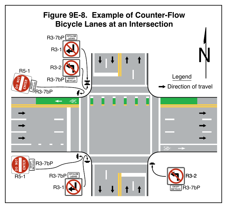
01. Counter-flow bicycle lanes are one-directional and provide a lawful path of travel for bicycles in the opposite direction from general traffic on a roadway that allows general traffic to travel in only one direction.
02. Counter-flow bicycle lanes establish two-way traffic on a roadway. Section 9B.21 contains information on the Left Turn Yield to Bicycles (R10-12b) sign used with traffic signals and counter-flow bicycle lanes.
Guidance
03. Where used, a counter-flow bicycle lane should be marked such that bicycles in the counter-flow lane travel on their right-hand side of the road in accordance with normal rules of the road, with opposing traffic on the left.
Standard
04. Counter-flow bicycle lanes located at the edge of the roadway shall use double yellow center line pavement markings (see Section 3B.01), a painted median island, a raised median island (see Chapter 3J), or some form of physical separation where the speed limit is 30 mph or less.
05. For speed limits 35 mph or greater, a buffer per Section 3B.25, a painted or raised median island, or some form of physical separation shall be used to separate a counter-flow bicycle lane from the adjacent travel lane.
Guidance
06. Lane extension markings should be used where counter-flow bicycle movements cross intersections.
07. Counter-flow bicycle lanes should not be used between a general-purpose lane and an on-street parallel parking lane for motor vehicles.
Support
08. Counter-flow bicycle lanes located between a general-purpose lane and an on-street parallel parking lane for motor vehicles can limit visibility of bicycles for vehicles exiting the parking lane, potentially impacting the safety of bicyclists. Locating counter-flow bicycle lanes at the edge of the roadway can reduce conflicts for bicycles.
Standard
09. Where signs are provided to regulate turns from streets or driveways that intersect with a roadway that has a counter-flow bicycle lane, ONE WAY signs (see Section 2B.49) shall not be used. Movement Prohibition signs (see Section 2B.26) with supplemental EXCEPT BICYCLES (R3-7bP) regulatory plaque(s) shall be used (see Figure 9E-8).
10. If a DO NOT ENTER (R5-1) sign(s) is used at egress points for motor vehicle traffic, the EXCEPT BICYCLES (R3-7bP) regulatory plaque(s) shall be placed under the DO NOT ENTER sign (see Figure 9E-8) where a counter-flow bicycle lane is used.
11. Where intersection traffic controls are provided (such as STOP or YIELD signs or traffic signals), appropriate devices shall be provided and oriented toward bicyclists in the counter-flow lane.
12. At signalized locations, appropriate bicycle signalization (see Chapter 9F) shall be provided and oriented toward bicyclists in the counter-flow lane, including a method for counter-flow bicycles to actuate the green phase for the counter-flow movement.
Support
13. Higher levels of traffic control or additional signalization, signing, and/or pavement marking treatments can be helpful for intersecting traffic where the counter-flow bicycle movement is unexpected.
Guidance
14. A Bicycle Cross Traffic warning plaque (see Section 9C.06) should be used below a STOP sign on the crossroad at intersections where a counter-flow bicycle lane is provided on the primary street.
§9E.09 Shared-Lane Marking¶
Support
01. The “Standard Highway Signs” publication (see Section 1A.05) R3-7bP contains details on the shared-lane marking symbol. R3-7bP
Option
02. The shared-lane marking shown in Figure 9E-9 may be used to:
- A. Assist bicyclists with lateral positioning in a shared lane with on-street parallel parking in order to reduce the chance of a bicyclist impacting the open door of a parked vehicle,
- B. Assist bicyclists with lateral positioning in lanes that are too narrow for a motor vehicle and a bicycle to travel side-by-side within the same traffic lane,
- C. Alert road users of the lateral location bicycles are likely to occupy within the traveled way,
- D. Encourage safe passing of bicycles by motor vehicles,
- E. Reduce the incidence of wrong-way bicycling in the roadway, and
- F. Assist bicyclists with lateral positioning in mixing zones.
Guidance
03. The shared-lane marking should not be placed on roadways that have a speed limit of 40 mph or greater.
Standard
04. Shared-lane markings shall not be used in:
- A. Shoulders;
- B. Bicycle lanes or in designated extensions of bicycle lanes through intersections or driveways,
- C. A travel lane in which light-rail transit vehicles also travel;
- D. The transition area where a motor vehicle entering a mandatory turn lane must weave across bicyclists in bicycle lanes;
- E. Two-stage turn boxes;
- F. Bicycle boxes;
- G. Shared-use paths or shared-use path crossings; or
- H. Physically-separated bikeways, either in the roadway or on an independent right-of-way.
05. Green-colored pavement shall not be applied as a background to shared-lane markings (see Section 3H.06).
Option
06. Black background markings (see Section 3A.03) may be used in combination with shared-lane markings to enhance contrast.
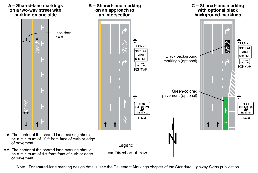
Note: For shared-lane marking design details, see the Pavement Markings chapter of the Standard Highway Signs publication
Guidance
If used in a shared lane with on-street parallel parking, shared-lane markings should be placed so that the centers of the markings are a minimum of 12 feet from the face of the curb, or from the edge of the pavement where there is no curb.
08. If used on a street without on-street parking that has an outside travel lane that is less than 14 feet wide, shared-lane markings should be placed so that the centers of the markings are a minimum of 4 feet from the face of the curb, or from the edge of the pavement where there is no curb.
09. At non-intersection locations, the shared-lane marking should be spaced at intervals of not less than 50 feet or greater than 250 feet.
10. The first shared-lane marking downstream from an intersection should be placed no more than 50 feet from the intersection.
Option
11. Section 9B.14 describes a Bicycles Allowed Use of Full Lane sign that may be used in addition to or instead of the shared-lane marking to inform road users that bicyclists might occupy the travel lane.
Guidance
12. If the Bicycles Allowed Use of Full Lane (R9-20) sign is used as an addition to shared-lane marking, the shared-lane marking should be placed so that the center of the marking is in the approximate center of the travel lane.
Option
13. The shared-lane marking may be used (see Figure 9E-9) where the width of the roadway is insufficient to continue a bicycle lane or separated bikeway on the approach to the intersection, or it is advantageous to terminate the bicycle lane or separated bikeway in order to provide for a shared lane.
14. The shared-lane marking may be used on an approach to an intersection (see Figure 9E-5) in a mandatory turn lane to indicate a shared space for bicyclists and motorists where there is insufficient width in the roadway for both the bicycle lane and turn lane.
§9E.10 Shared-Lane Markings for Circular Intersections¶
Option
01. Shared-lane markings may be used in the circulatory roadway of circular intersections.
Guidance
02. If used, shared-lane markings should be placed in the center of the lane when used inside of circulatory roadways.
Support
03. The “Guide for Development of Bicycle Facilities,” 2012 Fourth Edition, American Association of State Highway and Transportation Officials, contains information on designing for bicycles on shared-used paths in lieu of, or in addition to, using shared-lane markings in the circulatory roadway of the intersection.
§9E.11 Two-Stage Bicycle Turn Boxes¶
Support
01. Two-stage bicycle turn boxes allow bicyclists the opportunity to make turns at an intersection or crossing point instead of requiring them to merge into traffic upstream or to dismount and use a crosswalk at the intersection or crossing point.
02. Section 9B.18 contains information on regulatory signing that shall be used in conjunction with a two-stage bicycle turn box pavement marking where bicyclists are required to use the turn box.
03. Section 9D.13 contains information on guide signing that can be used in conjunction with a two-stage bicycle turn box pavement marking where bicyclists are not required to use the turn box.
Standard
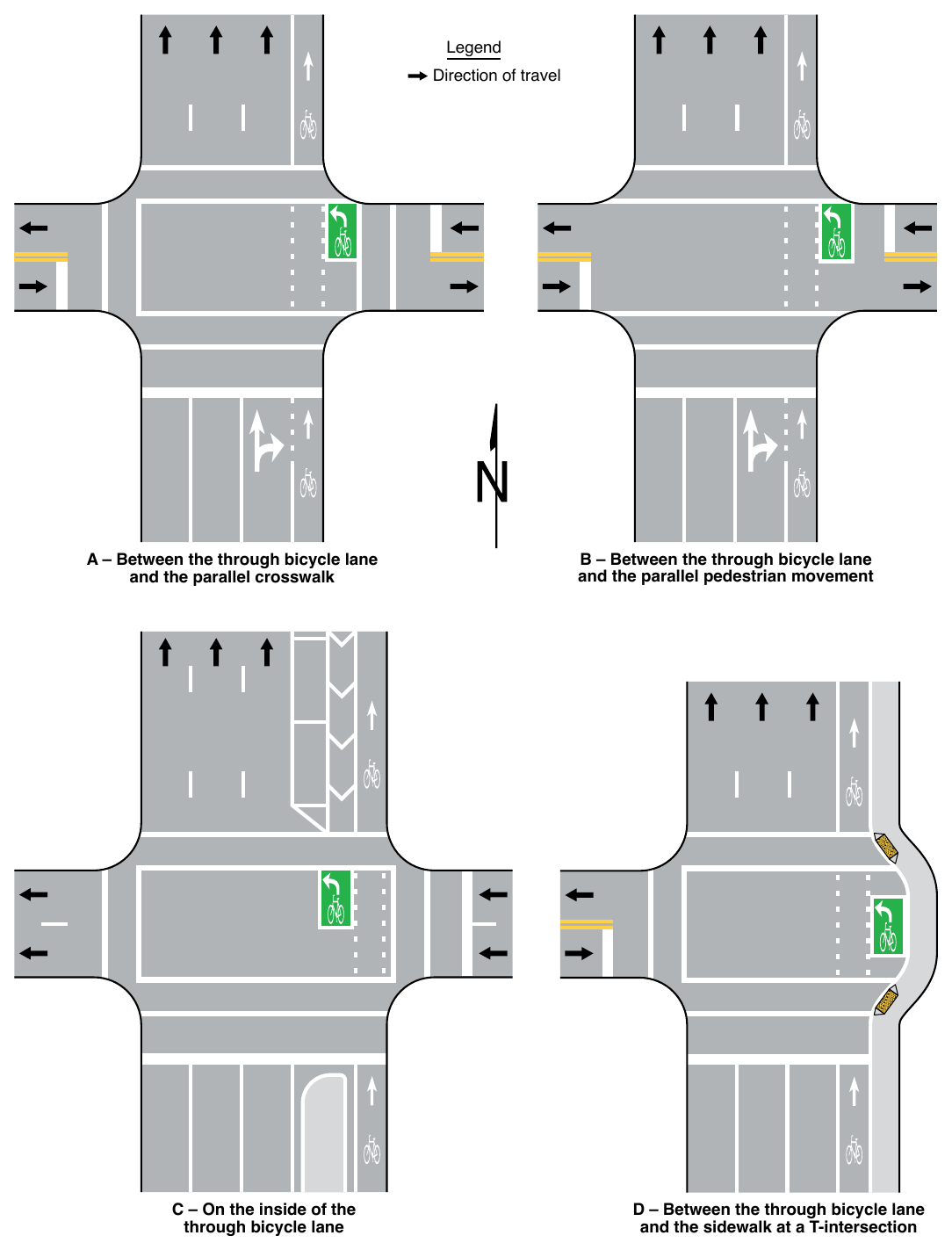
04. If used, two-stage bicycle turn boxes shall be located:
- A. In an area between the closest through bicycle or motor vehicle movement and the parallel crosswalk (see Drawing A in Figure 9E-10),
- B. In an area between the through bicycle movement and the parallel pedestrian crossing movement if no crosswalk is established (see Drawing B in Figure 9E-10),
- C. On the innermost side of the bicycle facility provided that the two-stage turn box is located in a portion of the intersection where parallel motor vehicle traffic does not travel, such as projections of islands or parking lanes (see Drawing C in Figure 9E-10), or
- D. In an area between the through bicycle movement and a pedestrian facility for T-intersections (see Drawing D in Figure 9E-10).
05. A two-stage bicycle turn box shall consist of at least one bicycle symbol pavement marking and at least one pavement marking arrow.
06. A turn arrow in the appropriate direction shall be used if a two-stage turn box is used with a one-way bicycle lane, and a through arrow in the appropriate direction shall be used if a two-stage turn box is used with a two-way bikeway (see Figure 9E-11).
07. A two-stage bicycle turn box shall be bounded on all sides by a solid white line.
08. For two-stage bicycle turn boxes that facilitate turns from a one-way bikeway, the bicycle symbol shall precede the pavement marking turn arrow in the direction of bicycle travel (see Figure 9E-10).
09. Passive detection of bicycles in the two-stage bicycle turn box shall be provided if the signal phase that permits bicycles to enter the intersection during the second stage of their turn is actuated.
Guidance
10. Engineering judgment should be used to develop the size of the two-stage bicycle turn box. Factors considered should include intersection geometry and keeping queued bicycles away from moving traffic, as well as peak hour bicycle volumes to avoid overflow of the two-stage turn box that subjects any bicyclist to conflicting movements.
Option
11. The two-stage turn box may use green-colored pavement.
Standard
12. If used, green-colored pavement shall encompass all of the two-stage turn box.
13. Where the path of vehicles lawfully turning on red would pass through a two-stage bicycle turn box, a full-time no-turn-on-red prohibition (see Section 2B.60) shall be provided for the crossroad approach.
§9E.12 Bicycle Box¶
Option
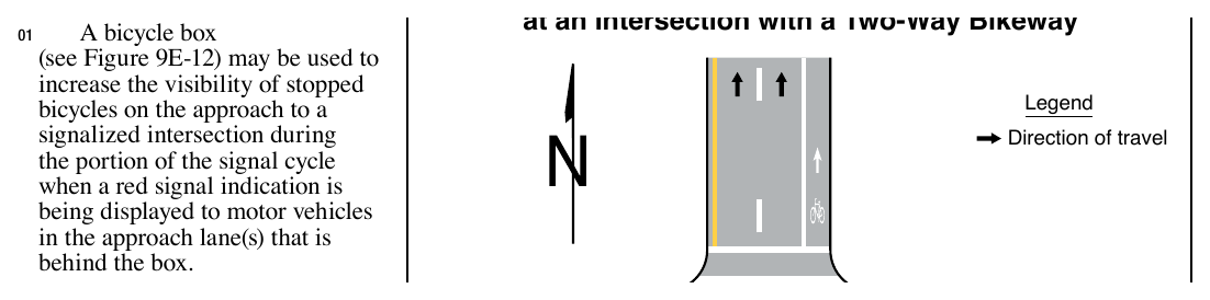
at an Intersection with a Two-Way Bikeway
01. A bicycle box (see Figure 9E-12) may be used to increase the visibility of stopped bicycles on the approach to a signalized intersection during the portion of the signal cycle when a red signal indication is being displayed to motor vehicles in the approach lane(s) that is behind the box.
Guidance
02. Providing a bicycle box on a signalized intersection approach where a discernible number of conflicts between vehicles turning across through bicycles in a bicycle lane has been demonstrated during the green interval of a signal should be evaluated based on engineering judgment or study.
03. Other treatments should be considered for conflicts between turning vehicles and through bicycles such as using leading or exclusive signal phases, or separating turning traffic from through traffic through mandatory turn lanes.
04. A bicycle lane should be used on the approach to a bicycle box.
05. A bicycle box should not be contiguous with a crosswalk. A stop line on the downstream end of the bicycle box should be used to mark the location where bicycles are required to stop.
Standard
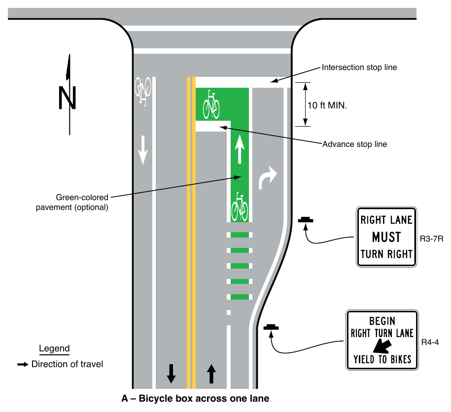
06. If used, the distance from the upstream edge of the bicycle box that is nearest to the stop line for motor vehicles to the downstream edge of the bicycle box that is nearest the crosswalk or intersection shall be at least 10 feet. At least one bicycle symbol marking (see Figure 9E-12) shall be used in the bicycle box.
07. Where an existing stop line for motor vehicles is relocated upstream to install a new bicycle box, the yellow change and red clearance intervals (see Section 4F.17) shall be recalculated and if necessary, reprogrammed to accommodate the length of the bicycle box.
08. Countdown pedestrian signals (see Section 4I.04) for the crosswalk or pedestrian crossing movement that crosses the approach shall accompany bicycle boxes that extend across more than one approach lane for motor vehicles. Countdown pedestrian signals used with bicycle boxes shall display the pedestrian change interval countdown without the need for actuation.
09. Turns on red shall be prohibited from the lane where a bicycle box is placed.
Support
10. Countdown pedestrian signals can inform bicyclists whether there is adequate time remaining to an adjacent lane before the onset of the green signal phase for that approach.
Guidance
11. Countdown pedestrian signals for the crosswalk or pedestrian crossing movement that crosses the approach should accompany single-lane bicycle boxes where it is demonstrated that bicycles arrive at the intersection at or near the end of the red signal indication being displayed to traffic in the approach lane(s) that is behind the box.
Option
12. Green-colored pavement may be used in a bicycle box.
Standard
13. If used, green-colored pavement shall be used in the full limits of the bicycle box.
Support
14. Section 9B.02 contains information on the EXCEPT BICYCLES (R3-7bP) regulatory plaque that can be used below the STOP HERE ON RED (R10-6 or R10-6a) sign (see Section 2B.59) to exempt bicyclists from the requirement of the advance stop line.
§9E.13 Shared-Use Paths¶
Option
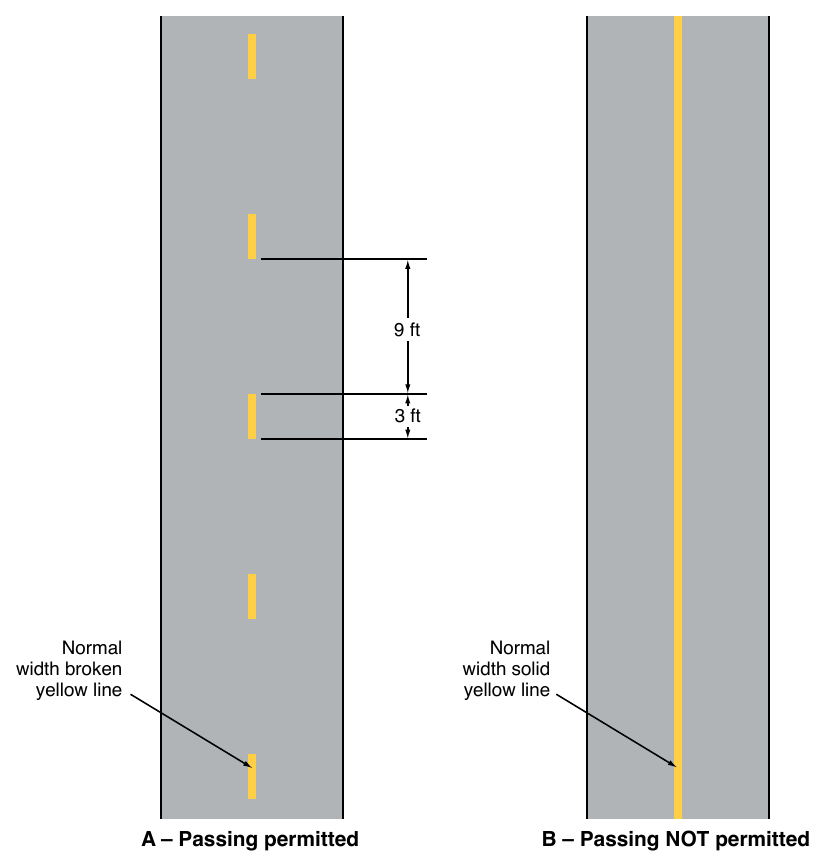
01. Where shared-use paths are of sufficient width to designate two minimum width lanes, a solid yellow center line may be used to separate the two directions of travel where passing or traveling to the left of the line is not permitted. A broken yellow center line may be used where passing is permitted (see Figure 9E-13).
Guidance
02. Broken lines used on shared-use paths should have a nominal 3-foot segment with a 9-foot gap.
Option
03. A solid white line may be used on shared-use paths to separate different types of users in the same direction. The R9-7 sign (see Section 9B.13) may be used to supplement the solid white line.
04. Smaller size pavement word markings and symbols may be used on shared-use paths. Where arrows are needed on shared-use paths, half-size layouts of the arrows may be used (see Section 3B.20).
Standard
05. Where a shared-use path crosses a roadway, crosswalk markings shall be used (see Chapter 3C).
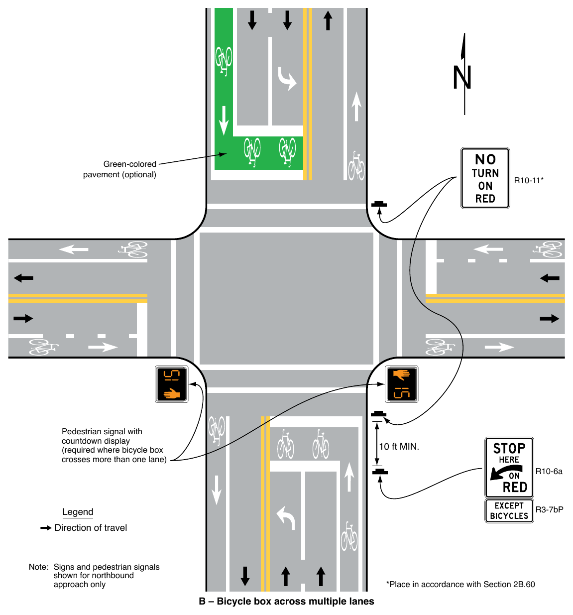
Note: Signs and pedestrian signals shown for northbound approach only *Place in accordance with Section 2B.60 B – Bicycle box across multiple lanes
Option
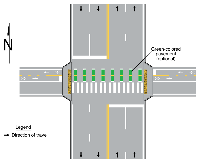
Where pedestrian and bicycle movements on a shared-use path are separated on the approach to a roadway crossing, parallel bicycle and pedestrian crossing markings may be used as shown in Figure 9E-14.
Guidance
07. If parallel bicycle and pedestrian crossing markings are used where a shared-use path crosses a roadway, crossing areas for bicycles should use green-colored pavement if the shared-use path crossing has a high volume of either mode.
§9E.14 Bicycle Route Pavement Markings¶
Option
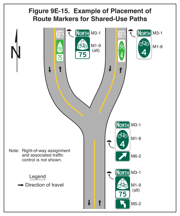
01. Bicycle route pavement markings simulating guide signs for bicycle routes (see Section 9D.02 through 9D.07) and route auxiliary plaques (see Section 9D.08) may be used to supplement guide signing to help bicyclists in navigation (see Figure 9E-15).
Standard
02. Bicycle route pavement markings shall be limited to shared-use paths, separated bicycle lanes, or buffer-separated bicycle lanes. Bicycle route pavement markings shall not be used in standard bicycle lanes or in shared lanes.
Guidance
03. A systematic methodology of locating guide signs for bicycle routes adjacent to the bicycle route pavement marking should be used that includes locations where either the sign or the pavement marking can exist alone to avoid overuse of the guide sign or the pavement marking.
04. The route marker pavement marking should be elongated.
05. The location, size, and materials of the route marker pavement marking should be designed in a manner that will minimize the loss of traction for bicyclists under wet conditions.
Signs shown: R10-22
§9E.15 Bicycle Detector Symbol¶
Option
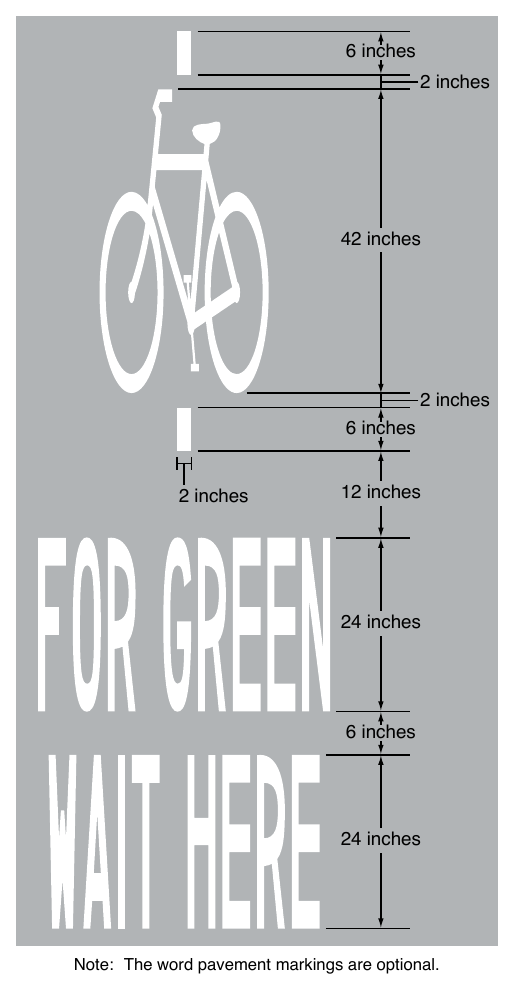
01. The bicycle detector symbol (see Figure 9E-16) may be placed on the pavement indicating the optimum position for a bicycle to actuate the signal.
02. Appropriately-sized WAIT HERE FOR GREEN word markings may be placed on the pavement immediately below the bicycle detector symbol.
03. A R10-22 sign (see Section 9B.20) may be installed to supplement the bicycle detector symbol pavement marking.
Support
04. The “Standard Highway Signs” publication (see Section 1A.05) contains details on the bicycle detector symbol.
05. Section 3H.06 contains information on incorporating green-colored pavement as a background enhancement to the bicycle detector symbol.
§9E.16 Pavement Markings for Obstructions¶
Guidance
01. Markings as shown in Figure 9E-17 should be used at the location of obstructions in the center of a shared-use path or a physically-separated bikeway, including vertical elements intended to physically prevent unauthorized motor vehicles from entering the path.
02. For roadway situations where it is impracticable to eliminate a drain grate or other roadway obstruction that is inappropriate for bicycle travel, white markings applied as shown in Figure 9E-17 should be used to guide bicyclists around the condition.
§9E.17 Raised Devices¶
Support
01. Chapter 3I contains information on using channelizing devices to emphasize pavement marking patterns associated with certain bicycle facilities. A common application is the use of flexible raised devices to create separated bicycle lanes (see Section 9E.07).
02. Using inflexible raised devices immediately adjacent to the travel path of a bicyclist without a buffer creates a collision potential for bicyclists.
Option
03. In accordance with Chapter 3I, channelizing devices may be used to emphasize a pavement marking pattern that establishes a bicycle lane or other bicycle facility provided that the installation of channelizing devices does not prevent motor vehicles from turning when the turn requires the motor vehicle to merge with the bicycle lane or facility as required by law or ordinance.
Guidance
04. If used, channelizing devices for bicycle facilities should be tubular markers (see Section 3I.02).
05. The selection of a raised device for use with bicycle facilities should consider the collision potential of both the post and the base since the base might still be present in the event the post is struck and missing.
Support
06. Measures to reduce the likelihood of a road user striking a channelizing device include marking a buffer space, improving lighting, improving retroreflectivity, or the periodic addition of taller vertical elements within runs of shorter elements.
Standard
07. Channelizing devices that are used to emphasize the pavement marking patterns of bicycle facilities shall not incorporate the color green into either the device or its retroreflective element to supplement the presence of green-colored pavement.
Guidance
08. If used in separated bicycle lanes, channelizing devices should be placed in the buffer space and at least 1 foot from the longitudinal bicycle lane pavement marking.
Note: The word pavement markings are optional.
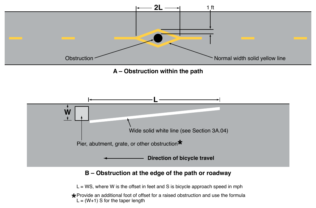
L = WS, where W is the offset in feet and S is bicycle approach speed in mph