2E. Guide Signs: Freeways & Expressways¶
Chapter 2E. GUIDE SIGNS—FREEWAYS AND EXPRESSWAYS¶
§2E.01 Scope of Freeway and Expressway Guide Sign Standards¶
Support
01. The provisions of this Chapter provide a uniform and effective system of signing for high-volume, high-speed motor vehicle traffic on freeways and expressways. The requirements and specifications for expressway signing exceed those for conventional roads (see Chapter 2D), but are less than those for freeway signing. Since there are many geometric design variables to be found in existing roads, a signing concept commensurate with prevailing conditions is the primary consideration. Section 1C.02 includes definitions of freeway and expressway.
02. Guide signs for freeways and expressways are primarily identified by the name of the sign rather than by an assigned sign designation. Guidelines for the design of guide signs for freeways and expressways are provided in the “Standard Highway Signs” publication (see Section 1A.05).
Standard
03. The provisions of this Chapter shall apply to any highway that meets the definition of freeway or expressway facilities.
§2E.02 Freeway and Expressway Signing Principles¶
Support
01. The development of a signing system for freeways and expressways is approached on the premise that the signing is primarily for the benefit and direction of road users who are unfamiliar with the route or area. The signing furnishes road users with clear instructions for orderly progress to their destinations. Sign installations are an integral part of the facility and, as such, are best planned concurrently with the development of highway location and geometric design. For optimal results, plans for signing are analyzed during the earliest stages of preliminary design, and details are correlated as final design is developed. The excessive signing found on many major highways usually is the result of using a multitude of signs that are too small and that are poorly designed and placed to accomplish the intended purpose.
02. Freeway and expressway signing is to be considered and developed as a planned system of installations. An engineering study is sometimes necessary for proper solution of the problems of many individual locations, but, in addition, consideration of an entire route is necessary.
Guidance
03. Road users should be guided with consistent signing on the approaches to interchanges, when they drive from one State to another, and when driving through rural or urban areas. Because geographical, geometric, and operating factors regularly create significant differences between urban and rural conditions, the signing should take these conditions into account.
04. Guide signs on freeways and expressways should serve distinct functions as follows:
- A. Give directions to destinations, or to streets or highway routes, at intersections or interchanges;
- B. Furnish advance notice of the approach to intersections or interchanges;
- C. Direct road users into appropriate lanes in advance of diverging or merging movements;
- D. Identify routes and directions on those routes;
- E. Show distances to destinations;
- F. Indicate access to general motorist services, rest, scenic, and recreational areas; and
- G. Provide other information of navigational value to the road user.
§2E.03 Guide Sign Classification¶
Support
01. Freeway and expressway guide signs are classified and addressed as follows:
- A. Interchange signs (see Sections 2E.21 through 2E.23 and 2E.25 through 2E.44);
- B. Interchange Sequence signs (see Section 2E.24);
- C. Post-Interchange signs (see Sections 2E.47 through 2E.49);
- D. Community Interchanges Identification signs (see Section 2E.52);
- E. Next Exits signs (see Section 2E.53);
- F. Weigh Station signs (see Section 2E.54);
- G. Route signs and Trailblazer Assemblies (see Section 2E.55);
- H. General Information signs (see Chapter 2H);
- I. Reference Location signs (see Sections 2H.11 and 2H.12);
- J. General Service signs (see Chapter 2I);
- K. Rest and Scenic Area signs (see Section 2I.05);
- L. Tourist Information and Welcome Center signs (see Section 2I.08);
- M. Radio Information, Travel Information, and Roadside Assistance signs (see Sections 2I.09 through 2I.13);
- N. Carpool and Ridesharing signs (see Section 2I.14);
- O. Specific Service signs (see Chapter 2J); and
- P. Recreational and Cultural Interest Area signs (see Chapter 2M).
§2E.04 Characteristics of Urban Signing¶
Support
01. Urban conditions are characterized not so much by city limits or other arbitrary boundaries as by the following features:
- A. Mainline roadways with more than two lanes in each direction;
- B. High traffic volumes on the through roadways;
- C. High volumes of traffic entering and leaving interchanges;
- D. Interchanges that are closely spaced;
- E. Roadway and interchange lighting;
- F. Three or more interchanges serving the major city;
- G. A loop, circumferential, or spur route serving a sizable portion of the urban population; and
- H. Visual clutter from roadside development.
02. Operating conditions and road geometrics on urban freeways and expressways usually make special sign treatments desirable, including:
- A. Use of Interchange Sequence signs (see Section 2E.24);
- B. Use of sign spreading to the maximum extent possible (see Section 2E.43);
- C. Elimination of General Service or Specific Service signing (see Chapters 2I and 2J);
- D. Reduction to a minimum of post-interchange signs (see Section 2E.47);
- E. Display of advance signs at distances closer to the interchange, with appropriate adjustments in the legend (see Section 2E.23);
- F. Use of overhead signs on roadway structures and independent sign supports (see Section 2E.19);
- G. Use of Overhead Arrow-per-Lane guide signs in advance of interchanges with option lanes (see Section 2E.40), or Diagrammatic Advance guide signs in advance of interchanges with complex geometric configurations of ramp departures (see Section 2E.41); and
- H. Frequent use of street names as the principal message in guide signs.
03. Lower speeds, which are often characteristic of urban operations, do not justify lower signing standards. Typical traffic patterns are more complex for the road user to negotiate, and large, easy-to-read legends are, therefore, just as necessary as on rural highways.
§2E.05 Characteristics of Rural Signing¶
Support
01. Rural areas ordinarily have greater distances between interchanges, which permits adequate spacing for the sequences of signs on the approach to and departure from each interchange. However, the absence of traffic in adjoining lanes and on entering or exiting ramps often adds monotony or inattention to rural driving. This increases the importance of signs that call for decisions or actions.
Guidance
02. Where there are long distances between interchanges and the alignment is relatively unchanging, signs should be positioned for their best effect on road users. The tendency to group all signing in the immediate vicinity of rural interchanges should be avoided by considering the entire route in the development of signing plans. Extra effort should be given to the placement of signs at natural target locations to command the attention of the road user, particularly when the message requires an action by the road user.
§2E.06 Signing of Named Highways¶
Guidance
01. Signing of named highways on freeways and expressways should comply with the provisions of Section 2D.56.
Support
02. Section 2M.10 contains information regarding memorial or dedication signing of routes, bridges, or highway components.
§2E.07 Designation of Destinations¶
Standard
01. The direction of a freeway and the major destinations or control cities along it shall be clearly identified through the use of appropriate destination legends (see Section 2D.35). Successive freeway guide signs shall provide continuity in destination names and consistency with available map information. At any decision point, a given destination shall be indicated by way of only one route (see Figure 2E-1).
Guidance
02. Control city legends should be used in the following situations along a freeway:
- A. At interchanges between freeways;
- B. At separation points of overlapping freeway routes;
- C. On directional signs on intersecting routes, to guide traffic entering the freeway;
- D. On Pull-Through signs; and
- E. On the bottom line of post-interchange distance signs.
Support
03. Continuity of destination names is also useful on expressways serving long-distance or intrastate travel.
04. The determination of major destinations or control cities is important to the quality of service provided by the freeway. Control cities on freeway guide signs are selected by the States and are contained in the “Guidelines for the Selection of Supplemental Guide Signing, 5th Edition,” 2016, AASHTO.
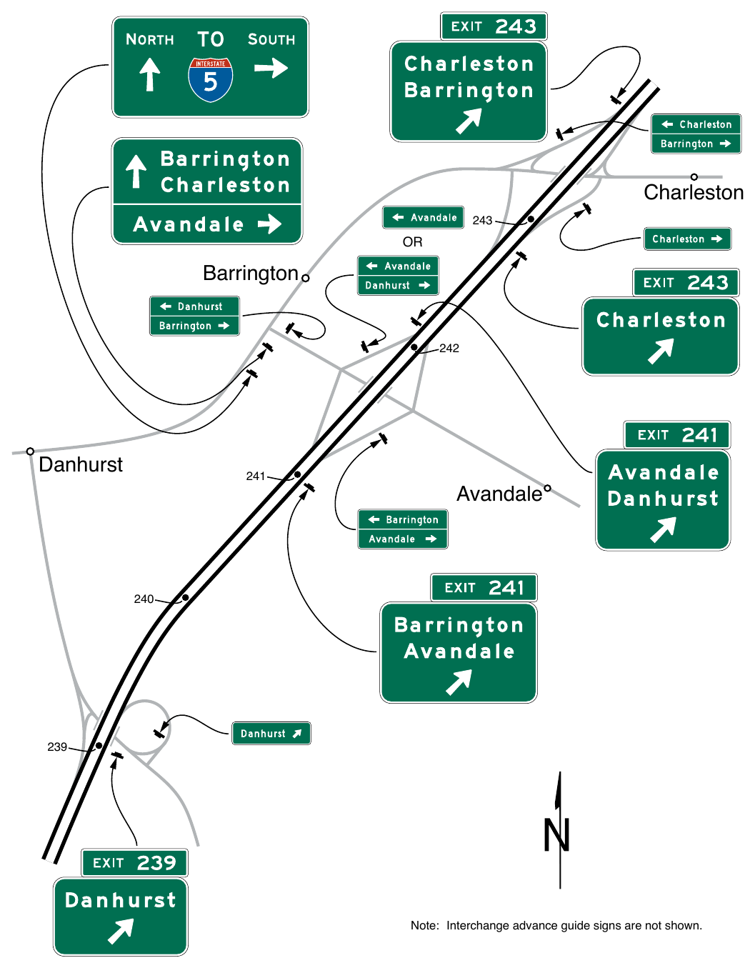
Note: Interchange advance guide signs are not shown.
SIGN DESIGN¶
§2E.08 General¶
Support
01. Effective signs are legible to road users approaching them, and are readable and comprehensible in the viewing time provided to permit proper responses. Desired design characteristics include: (a) long visibility distances; (b) large lettering, symbols, and arrows; and (c) short legends.
§2E.09 Color of Guide Signs¶
Standard
01. Guide signs on freeways and expressways, except as otherwise provided in this Manual, shall have white letters, symbols, arrows, and borders on a green background.
Support
02. Color requirements for route signs and trailblazers; for signs with blank-out or changeable messages; for signs for services, rest areas, park and recreational areas; and for certain miscellaneous signs are provided in the individual Sections dealing with the particular sign or sign group.
§2E.10 Retroreflection or Illumination¶
Standard
01. Letters, numerals, symbols, arrows, and borders of all guide signs shall be retroreflective. The background of all guide signs that are not independently illuminated shall be retroreflective.
Support
02. Where there is no serious interference from extraneous light sources, retroreflective post-mounted signs usually provide adequate nighttime visibility.
03. On freeways and expressways where much driving at night is done with low-beam headlights, the amount of headlight illumination incident to an overhead sign display is relatively small.
Guidance
04. Overhead sign installations should be illuminated (see Section 2A.21) unless an engineering study shows that retroreflection alone will perform effectively. The type of illumination chosen should provide effective and reasonably uniform illumination of the sign face and message.
§2E.11 Interchange Classification¶
Support
01. For signing purposes, interchanges are classified as major, intermediate, and minor. Minimum letter and numeral sizes based on interchange classification are contained in Tables 2E-2 and 2E-4. Descriptions of these classifications are as follows:
- A. Major interchanges are subdivided into two categories: (a) interchanges with other expressways or freeways, or (b) interchanges with high-volume multi-lane highways, principal urban arterials, or major rural routes where the volume of interchanging traffic is heavy or includes many road users unfamiliar with the area.
- B. Intermediate interchanges are those with urban and rural routes not in the category of major or minor interchanges.
- C. Minor interchanges include those where traffic is local and very light, such as interchanges with land service access roads. Where the sum of exit volumes is estimated to be lower than 100 vehicles per day in the design year, the interchange is classified as minor.
§2E.12 Size of Signs and Letters¶
Standard
01. Except as provided in Section 2A.07, the sizes of freeway and expressway guide signs that have standardized designs shall be as shown in Table 2E-1.
Support
02. Section 2A.07 contains information regarding the applicability of the various columns in Table 2E-1.
Option
03. Signs larger than those shown in Table 2E-1 may be used (see Section 2A.07).
Table 2E-1. Freeway or Expressway Guide Sign and Plaque Sizes (Sheet 1 of 3)
| Sign or Plaque | Sign Designation | Section | Minimum Size |
|---|---|---|---|
| Interchange Advance Guide (1 destination) | E1-1 | 2E.23 | Varies |
| Interchange Advance Guide (2 destinations) | E1-2 | 2E.23 | Varies |
| Interchange Advance Guide (3 destinations) | E1-3 | 2E.23 | Varies |
| Exit Number (plaque) | |||
| 1-, 2-Digit Exit Number | E1-5P | 2E.23 | 114 x 30 |
| 3-Digit Exit Number | E1-5aP | 2E.23 | 132 x 30 |
| 1-, 2-Digit Exit Number (with single-letter suffix) | E1-5bP | 2E.23 | 138 x 30 |
| 3-Digit Exit Number (with single-letter suffix) | E1-5cP | 2E.23 | 156 x 30 |
| 1-, 2-Digit Exit Number (with dual-letter suffix) | E1-5dP | 2E.23 | 168 x 30 |
| 3-Digit Exit Number (with dual-letter suffix) | E1-5eP | 2E.23 | 186 x 30 |
| Left Exit Number (plaque) | |||
| 1-, 2-Digit Exit Number | E1-5fP | 2E.23 | 114 x 54 |
| 3-Digit Exit Number | E1-5gP | 2E.23 | 132 x 54 |
| 1-, 2-Digit Exit Number (with single-letter suffix) | E1-5hP | 2E.23 | 138 x 54 |
| 3-Digit Exit Number (with single-letter suffix) | E1-5iP | 2E.23 | 156 x 54 |
| 1-, 2-Digit Exit Number (with dual-letter suffix) | E1-5jP | 2E.23 | 168 x 54 |
| 3-Digit Exit Number (with dual-letter suffix) | E1-5kP | 2E.23 | 186 x 54 |
| Left (plaque) | E1-5mP | 2E.23 | 72 x 30 |
| Next Exit (1 line) (plaque) | E2-1P | 2E.46 | Varies x 24 |
| Next Exit (2 lines) (plaque) | E2-1aP | 2E.46 | Varies x 36 |
| Supplemental (1 destination) | E3-1 | 2E.51 | Varies |
| Supplemental (2 destinations) | E3-2 | 2E.51 | Varies |
| Exit Direction (1 destination) | E4-1 | 2E.25 | Varies |
| Exit Direction (2 destinations) | E4-2 | 2E.25 | Varies |
| Exit Direction (3 destinations) | E4-3 | 2E.25 | Varies |
| Exit Gore | E5-1 | 2E.26 | 72 x 60 |
| Exit Gore (with exit number) | |||
| 1-, 2-Digit Exit Number | E5-1a | 2E.26 | 78 x 60 |
| 3-Digit Exit Number | E5-1a | 2E.26 | 96 x 60 |
| 1-Digit Exit Number (with single-letter suffix) | E5-1a | 2E.26 | 90 x 60 |
| 2-Digit Exit Number (with single-letter suffix) | E5-1a | 2E.26 | 108 x 60 |
| 3-Digit Exit Number (with single-letter suffix) | E5-1a | 2E.26 | 126 x 60 |
| 1-Digit Exit Number (with dual-letter suffix) | E5-1a | 2E.26 | 120 x 60 |
| 2-Digit Exit Number (with dual-letter suffix) | E5-1a | 2E.26 | 138 x 60 |
| 3-Digit Exit Number (with dual-letter suffix) | E5-1a | 2E.26 | 156 x 60 |
| Exit Number (plaque) | |||
| 1-, 2-Digit Exit Number | E5-1bP | 2E.26 | 42 x 30 |
| 3-Digit Exit Number | E5-1bP | 2E.26 | 60 x 30 |
| 1-Digit Exit Number (with single-letter suffix) | E5-1bP | 2E.26 | 54 x 30 |
| 2-Digit Exit Number (with single-letter suffix) | E5-1bP | 2E.26 | 72 x 30 |
| 3-Digit Exit Number (with single-letter suffix) | E5-1bP | 2E.26 | 90 x 30 |
| 1-Digit Exit Number (with dual-letter suffix) | E5-1bP | 2E.26 | 84 x 30 |
| 2-Digit Exit Number (with dual-letter suffix) | E5-1bP | 2E.26 | 102 x 30 |
| 3-Digit Exit Number (with dual-letter suffix) | E5-1bP | 2E.26 | 120 x 30 |
| Narrow Exit Gore | E5-1c | 2E.26 | 60 x 90* |
| Pull-Through | E6-1 | 2E.27 | Varies |
| Pull-Through (Destination) | E6-1a | 2E.27 | Varies |
| Pull-Through (Down Arrows) | E6-2 | 2E.27 | Varies |
Table 2E-1. Freeway or Expressway Guide Sign and Plaque Sizes (Sheet 2 of 3)
| Sign or Plaque | Sign Designation | Section | Minimum Size |
|---|---|---|---|
| Pull-Through (Destination, Down Arrows) | E6-2a | 2E.27 | Varies |
| Post-Interchange Distance | E7-1 | 2E.48 | Varies |
| Post-Interchange Distance | E7-2 | 2E.48 | Varies |
| Post-Interchange Distance | E7-3 | 2E.48 | Varies |
| Post-Interchange Travel Time | E7-4 | 2E.49 | Varies |
| Distance and Travel Time | E7-5 | 2E.50 | Varies |
| Comparative Travel Time | E7-6 | 2E.50 | Varies |
| Interchange Sequence (2 interchanges) | E9-1 | 2E.24 | Varies |
| Interchange Sequence (3 interchanges) | E9-2 | 2E.24 | Varies |
| Next Exits (1 destination) | E9-3 | 2E.53 | Varies |
| Next Exits (2 destinations) | E9-3a | 2E.53 | Varies |
| Community Interchanges (2 interchanges) | E9-4 | 2E.52 | Varies |
| Community Interchanges (3 interchanges) | E9-5 | 2E.52 | Varies |
| Exit Only (with arrow) | E11-1,1d | 2E.28 | 174** x 36 |
| Exit | E11-1a | 2E.28 | 66 x 18 |
| Only | E11-1b | 2E.28 | 66 x 18 |
| Exit Only | E11-1c | 2E.28 | 120 x 18 |
| Exit Only (with two arrows) | E11-1e,1f | 2E.28 | 222** x 36 |
| Left (panel) | E11-2 | 2E.24 | 60 x 18 |
| Exit Direction Advisory Speed (panel) | E13-2 | 2E.25 | 162 x 24 |
| Interstate Route (1, 2 digits) | M1-1 | 2E.55 | 36 x 36 |
| Interstate Route (3 digits) | M1-1 | 2E.55 | 45 x 36 |
| Off-Interstate Route (1, 2 digits) | M1-2,3 | 2E.55 | 36 x 36 |
| Off-Interstate Route (3 digits) | M1-2,3 | 2E.55 | 45 x 36 |
| U.S. Route (1, 2 digits) | M1-4 | 2E.55 | 36 x 36 |
| U.S. Route (3 digits) | M1-4 | 2E.55 | 45 x 36 |
| State Route (1, 2 digits) | M1-5 | 2D.11 | 36 x 36 |
| State Route (3 digits) | M1-5 | 2D.11 | 45 x 36 |
| County Route | M1-6 | 2D.11 | 36 x 36 |
| Forest Route | M1-7 | 2D.11 | 36 x 36 |
| Eisenhower Interstate System | M1-10,10a | 2E.56 | 36 x 36 |
| Junction (plaque) | M2-1P | 2D.13 | 30 x 21 |
| Combination Junction (2 route signs) | M2-2 | 2D.14 | 60 x 48* |
| Cardinal Direction (plaque) | M3-1P,2P,3P,4P | 2D.15 | 36 x 18 |
| Alternate (plaque) | M4-1P,1aP | 2D.17 | 36 x 18 |
| By-Pass (plaque) | M4-2P | 2D.18 | 36 x 18 |
| Business (plaque) | M4-3P | 2D.19 | 36 x 18 |
| Truck (plaque) | M4-4P | 2D.20 | 36 x 18 |
| To (plaque) | M4-5P | 2D.21 | 36 x 18 |
| End (plaque) | M4-6P | 2D.22 | 36 x 18 |
| Temporary (plaque) | M4-7P,7aP | 2D.24 | 36 x 18 |
| Begin (plaque) | M4-14P | 2D.23 | 36 x 18 |
| Advance Turn Arrow (plaque) | M5-1P,2P,3P | 2D.26 | 30 x 21 |
| Lane Designation (plaque) | M5-4P,5P,6P | 2D.27 | 36 x 24 |
| Directional Arrow (plaque) | M6-1P,2P, 2aP,3P,4P,5P,6P,7P | 2D.28 | 30 x 21 |
| National Scenic Byway | M10-1 | 2D.57 | 24 x 24 |
| National Scenic Byway (plaque) | M10-1aP | 2D.57 | 24 x 12 |
| Destination (1 line) | D1-1 | 2D.36 | Varies x 24 |
Table 2E-1. Freeway or Expressway Guide Sign and Plaque Sizes (Sheet 3 of 3)
| Sign or Plaque | Sign Designation | Section | Minimum Size |
|---|---|---|---|
| Destination and Distance (1 line) | D1-1a | 2D.36 | Varies x 24 |
| Destination (2 lines) | D1-2 | 2D.36 | Varies x 42 |
| Destination and Distance (2 lines) | D1-2a | 2D.36 | Varies x 42 |
| Destination (3 lines) | D1-3 | 2D.36 | Varies x 60 |
| Destination and Distance (3 lines) | D1-3a | 2D.36 | Varies x 60 |
| Distance (1 line) | D2-1 | 2D.43 | Varies x 24 |
| Distance (2 lines) | D2-2 | 2D.43 | Varies x 36 |
| Distance (3 lines) | D2-3 | 2D.43 | Varies x 48 |
| Street Name (1 line) | D3-1,1a | 2D.45 | Varies x 18 |
| Overhead Street Name (1 line) | D3-1,1a | 2D.45 | Varies x 24 |
| Street Name (2 lines) | D3-1,1a | 2D.45 | Varies x 33 |
| Overhead Street Name (2 lines) | D3-1,1a | 2D.45 | Varies x 48 |
| Advance Street Name (2 lines) | D3-2 | 2D.46 | Varies x 36 |
| Advance Street Name (3 lines) | D3-2 | 2D.46 | Varies x 48 |
| Advance Street Name (4 lines) | D3-2 | 2D.46 | Varies x 66 |
| Park - Ride | D4-2 | 2D.48 | 36 x 48 |
| Advance Weigh Station Distance | D8-1 | 2E.54 | 96 x 72 (F) 78 x 60 (E) |
| Weigh Station Advance Direction | D8-2 | 2E.54 | 108 x 90 (F) 84 x 72 (E) |
| Weigh Station Entrance Direction | D8-3 | 2E.54 | 84 x 78 (F) 66 x 60 (E) |
| Crossover | D13-1,2 | 2D.52 | 78 x 42 |
| Freeway Entrance | D13-3 | 2D.50 | 48 x 30 |
| Freeway Entrance (Directional) | D13-3a | 2D.50 | 48 x 42 |
| Combination Lane Use / Destination | D15-1 | 2D.38 | Varies x 96 |
| Next Truck Lane | D17-1 | 2D.53 | 60 x 66 |
| Advance Truck Lane | D17-2 | 2D.53 | 60 x 54 |
| Next Passing Lane | D17-3 | 2D.53 | 60 x 66 |
| Advance Passing Lane | D17-4 | 2D.53 | 60 x 54 |
| Advance Emergency Turn-Out | D17-5 | 2D.54 | 78 x 54 |
| Emergency Turn-Out (Directional) | D17-6 | 2D.54 | 78 x 60 |
| Advance Slow Vehicle Turn-Out | D17-7 | 2D.54 | 96 x 54 |
* The size shown is for a typical sign as illustrated in the figures in Chapters 2D and 2E. The size should be determined based on the amount of legend required for the sign.
** The width shown represents the minimum dimension. The width shall be increased as appropriate to match the width of the guide sign.
Notes: 1. Larger signs may be used when appropriate 2. Dimensions in inches are shown as width x height 3. Where two sizes are shown, the larger size is for freeways (F) and the smaller size is for expressways (E)
be determined based on the amount of legend required for the sign. match the width of the guide sign. Notes: 1. Larger signs may be used when appropriate
- 2. Dimensions in inches are shown as width x height
- 3. Where two sizes are shown, the larger size is for freeways (F) and the smaller size is for expressways (E)
Standard
The nominal loop height of the lower-case letters shall be ¾ of the height of the initial upper-case letter (see Paragraph 3 of Section 2D.05 for additional information on the specification of letter heights). Other word legends such as cardinal directions, action messages, and special characters shall be composed of all upper-case letters with a minimum letter height of 8 inches. Interline and edge spacing shall be as provided in Section 2E.13.
05. For all freeway and expressway signs that do not have a standardized design, the message dimensions shall be determined first, and the outside sign dimensions secondarily. Minimum numeral and letter sizes for expressway guide signs according to interchange classification, type of sign, and component of sign legend shall be as shown in Tables 2E-2 and 2E-3. Minimum numeral and letter sizes for freeway guide signs according to interchange classification, type of sign, and component of sign legend shall be as shown in Tables 2E-4 and 2E-5. The minimum numeral and letter sizes for overhead-mounted expressway and freeway guide signs shall be those shown in the “Overhead” columns of Tables 2E-2 and 2E-4, respectively, except where a larger minimum numeral or letter height is provided in the columns for the applicable type of interchange (major, intermediate, or minor).
06. All names of places, streets, and highways on freeway and expressway guide signs shall be composed of lower-case letters with initial upper-case letters. The letters and the numerals used shall be FHWA Standard Alphabet Series E (modified) as provided in the “Standard Highway Signs” publication (see Section 1A.05).
07. Lettering size on freeway and expressway signs shall be the same for both rural and urban conditions.
Table 2E-2. Minimum Letter and Numeral Sizes for Expressway Guide Signs According to Interchange Classification
| Type of Sign | Type of Interchange (see Section 2E.11) | Overhead* | |||
|---|---|---|---|---|---|
| Major | Intermediate | Minor | |||
| Category a | Category b | ||||
| A. Advance Guide, Exit Direction, and Overhead Guide Signs | |||||
| Exit Number Plaques | |||||
| Words | 10 | 10 | 10 | 8 | 10 |
| Numerals & Letters | 15 | 15 | 15 | 12 | 15 |
| Interstate Route Signs | |||||
| Numerals | 14** | — | — | — | 14** |
| 1- or 2-Digit Shields | 36 x 36 | — | — | — | 36 x 36 |
| 3-Digit Shields | 45 x 36 | — | — | — | 45 x 36 |
| U.S. or State Route Signs | |||||
| Numerals | 18 | 18 | 18 | 12 | 18 |
| 1- or 2-Digit Shields | 36 x 36 | 36 x 36 | 36 x 36 | 24 x 24 | 36 x 36 |
| 3-Digit Shields | 45 x 36 | 45 x 36 | 45 x 36 | 30 x 24 | 45 x 36 |
| U.S. or State Route Text Identification (Example: US 56) | |||||
| Numerals & Letters | 18 | 15 | 15 | 12 | 15 |
| Cardinal Directions | |||||
| First Letters | 18 | 15 | 12 | 10 | 15 |
| Rest of Word | 15 | 12 | 10 | 8 | 12 |
| Auxiliary and Alternative Route Legends (Examples: JCT, TO, ALT, BUSINESS) | |||||
| Words | 15 | 12 | 10 | 8 | 12 |
| Names of Destinations | |||||
| Upper-Case Letters | 20 | 16 | 13.33 | 10.67 | 16 |
| Lower-Case Letters | 15 | 12 | 10 | 8 | 12 |
| Distance Numbers | 18 | 15 | 12 | 10 | 15 |
| Distance Fraction Numerals | 12 | 10 | 10 | 8 | 10 |
| Distance Words | 12 | 10 | 10 | 8 | 10 |
| Action Message Words | 10 | 10 | 10 | 8 | 10 |
| B. Gore Signs | |||||
| Words | 10 | 10 | 10 | 8 | — |
| Numerals & Letters | 12 | 12 | 12 | 10 | — |
* Where a larger size is shown for the interchange classification of the interchange, that larger size is used for overhead-mounted guide signs for that interchange.
** Minimum size listed for 3-digit shields. Larger numeral sizes used for 1-digit, some 2-digit, and some 3-digit shields. See the Standard Highways Signs publication for more information on Route Sign numeral heights and Standard Alphabet series.
Note: Sizes are shown in inches and where applicable are shown as width x height
Numerals & Letters
15. U.S. or State Route Text Identification (Example: US 56) Numerals & Letters
12. Auxiliary and Alternative Route Legends (Examples: JCT, TO, ALT, BUSINESS)
08. Numerals & Letters
10. overhead-mounted guide signs for that interchange. shields. See the Standard Highways Signs publication for more information on Route Sign numeral heights and Standard Alphabet series. Note: Sizes are shown in inches and where applicable are shown as width x height
Table 2E-3. Minimum Letter and Numeral Sizes for Expressway Guide Signs According to Sign Type
| Type of Sign | Minimum Size |
|---|---|
| A. Pull-Through Signs | |
| Destinations — Upper-Case Letters | 13.33 |
| Destinations — Lower-Case Letters | 10 |
| Route Signs | |
| Numerals | 14* |
| 1- or 2-Digit Shields | 36 x 36 |
| 3-Digit Shields | 45 x 36 |
| Cardinal Directions — First Letters | 12 |
| Cardinal Directions — Rest of Word | 10 |
| B. Supplemental Guide Signs | |
| Exit Number — Words | 8 |
| Exit Number — Numerals and Letters | 12 |
| Place Names — Upper-Case Letters | 10.67 |
| Place Names — Lower-Case Letters | 8 |
| Action Messages | 8 |
| Route Signs | |
| Numerals | 9* |
| 1- or 2-Digit Shield | 24 x 24 |
| 3-Digit Shield | 30 x 24 |
| C. Interchange Sequence or Community Interchanges Identification Signs | |
| Words — Upper-Case Letters | 10.67 |
| Words — Lower-Case Letters | 8 |
| Numerals | 10.67 |
| Fraction Numerals | 8 |
| Route Signs | |
| Numerals | 9* |
| 1- or 2-Digit Shield | 24 x 24 |
| 3-Digit Shield | 30 x 24 |
| D. Next XX Exits Sign | |
| Place Names — Upper-Case Letters | 10.67 |
| Place Names — Lower-Case Letters | 8 |
| NEXT XX EXITS — Words | 8 |
| NEXT XX EXITS — Number | 12 |
| Type of Sign | Minimum Size |
|---|---|
| E. Distance Signs | |
| Words — Upper-Case Letters | 8 |
| Words — Lower-Case Letters | 6 |
| Numerals | 8 |
| Route Signs | |
| Numerals | 6* |
| 1- or 2-Digit Shield | 18 x 18 |
| 3-Digit Shield | 22.5 x 18 |
| F. General Service Signs (see Chapter 2I) | |
| Exit Number — Words | 8 |
| Exit Number — Numerals and Letters | 12 |
| Services | 8 |
| G. Rest Area, Scenic Area, and Roadside Area Signs (see Chapter 2I) | |
| Words | 10 |
| Distance Numerals | 12 |
| Distance Fraction Numerals | 8 |
| Distance Words | 8 |
| Action Message Words | 10 |
| H. Reference Location Signs (see Chapter 2H) | |
| Words | 4 |
| Numerals | 10 |
| I. Boundary and Orientation Signs (see Chapter 2H) | |
| Words — Upper-Case Letters | 8 |
| Words — Lower-Case Letters | 6 |
| J. Next Exit and Next Services Signs | |
| Words and Numerals | 8 |
| K. Exit Only Signs | |
| Words | 12 |
| L. Overhead Arrow-per-Lane and Diagrammatic Signs | |
| See Table 2E-5 | |
for 1-digit, some 2-digit, and some 3-digit shields. See the Standard Highways Signs publication for more information on Route Sign numeral heights and Standard Alphabet series. Note: Sizes are shown in inches and where applicable are shown as width x height
Support
Sign size is determined primarily in terms of the length of the message and the size of the lettering necessary for proper legibility. Letter style and height, and arrow design have been standardized for freeway and expressway signs to assure uniform and effective application.
09. Designs for upper-case and lower-case FHWA Standard Alphabets, together with tables of recommended letter spacing, are shown in the “Standard Highway Signs” publication (see Section 1A.05).
Guidance
10. Freeway lettering sizes (see Tables 2E-4 and 2E-5) should be used when expressway geometric design is comparable to freeway standards.
11. Other sign letter size requirements not specifically identified elsewhere in this Manual should be guided by these specifications. Abbreviations should be kept to a minimum, except as provided in Section 2E.16.
Table 2E-4. Minimum Letter and Numeral Sizes for Freeway Guide Signs According to Interchange Classification
| Type of Sign | Type of Interchange (see Section 2E.11) | Overhead* | |||
|---|---|---|---|---|---|
| Major | Intermediate | Minor | |||
| Category a | Category b | ||||
| A. Advance Guide, Exit Direction, and Overhead Guide Signs | |||||
| Exit Number Plaques | |||||
| Words | 10 | 10 | 10 | 10 | 10 |
| Numerals & Letters | 15 | 15 | 15 | 15 | 15 |
| Interstate Route Signs | |||||
| Numerals | 18/14** | — | — | — | 14** |
| 1- or 2-Digit Shields | 48 x 48/ 36 x 36 | — | — | — | 36 x 36 |
| 3-Digit Shields | 60 x 48/ 45 x 36 | — | — | — | 45 x 36 |
| U.S. or State Route Signs | |||||
| Numerals | 24/18 | 18 | 18 | 12 | 18 |
| 1- or 2-Digit Shields | 48 x 48/ 36 x 36 | 36 x 36 | 36 x 36 | 24 x 24 | 36 x 36 |
| 3-Digit Shields | 60 x 48/ 45 x 36 | 45 x 36 | 45 x 36 | 30 x 24 | 45 x 36 |
| U.S. or State Route Text Identification (Example: US 56) | |||||
| Numerals & Letters | 18 | 18/15 | 15 | 12 | 15 |
| Cardinal Directions | |||||
| First Letters | 18 | 15 | 15 | 10 | 15 |
| Rest of Words | 15 | 12 | 12 | 8 | 12 |
| Auxiliary and Alternative Route Legends (Examples: JCT, TO, ALT, BUSINESS) | |||||
| Words | 15 | 12 | 12 | 8 | 12 |
| Names of Destinations | |||||
| Upper-Case Letters | 20 | 20 | 16 | 13.33 | 16 |
| Lower-Case Letters | 15 | 15 | 12 | 10 | 12 |
| Distance Numbers | 18 | 18/15 | 15 | 12 | 15 |
| Distance Fraction Numerals | 12 | 12/10 | 10 | 8 | 10 |
| Distance Words | 12 | 12/10 | 10 | 8 | 10 |
| Action Message Words | 12 | 12/10 | 10 | 8 | 10 |
| B. Gore Signs | |||||
| Words | 12 | 12 | 12 | 8 | — |
| Numeral & Letters | 18 | 18 | 18 | 12 | — |
Numerals & Letters
18. U.S. or State Route Text Identification (Example: US 56) Numerals & Letters
12. Auxiliary and Alternative Route Legends (Examples: JCT, TO, ALT, BUSINESS)
08. Numeral & Letters
12. overhead-mounted guide signs for that interchange. shields. See the Standard Highways Signs publication for more information on Route Sign numeral heights and Standard Alphabet series. Notes: 1. Sizes are shown in inches and where applicable are shown as width x height
- 2. Slanted line (/) signifies separation of desirable and minimum sizes
Support
12. A sign mounted over a particular roadway lane to which it applies might have to be limited in horizontal dimension to the width of the lane, so that another sign can be placed over an adjacent lane. The necessity to maintain proper vertical clearance might also place a further limitation on the size of the overhead sign and the legend that can be accommodated.
Table 2E-5. Minimum Letter and Numeral Sizes for Freeway Guide Signs According to Sign Type
| Type of Sign | Minimum Size |
|---|---|
| A. Pull-Through Signs | |
| Destinations — Upper-Case Letters | 16 |
| Destinations — Lower-Case Letters | 12 |
| Route Signs | |
| Numerals | 14* |
| 1- or 2-Digit Shields | 36 x 36 |
| 3-Digit Shields | 45 x 36 |
| Cardinal Directions — First Letter | 15 |
| Cardinal Directions — Rest of Word | 12 |
| B. Supplemental Guide Signs | |
| Exit Number Words | 10 |
| Exit Number Numerals and Letters | 15 |
| Place Names — Upper-Case Letters | 13.33 |
| Place Names — Lower-Case Letters | 10 |
| Action Messages | 8 |
| Route Signs | |
| Numerals | 9* |
| 1- or 2-Digit Shield | 24 x 24 |
| 3-Digit Shield | 30 x 24 |
| C. Interchange Sequence or Community Interchanges Identification Signs | |
| Words — Upper-Case Letters | 13.33 |
| Words — Lower-Case Letters | 10 |
| Numerals | 13.33 |
| Fraction Numerals | 10 |
| Route Signs | |
| Numerals | 9* |
| 1- or 2-Digit Shield | 24 x 24 |
| 3-Digit Shield | 30 x 24 |
| D. Next X Exits Sign | |
| Place Names — Upper-Case Letters | 13.33 |
| Place Names — Lower-Case Letters | 10 |
| NEXT X EXITS — Words | 10 |
| NEXT X EXITS — Number | 15 |
| E. Distance Signs | |
| Words — Upper-Case Letters | 8 |
| Words — Lower-Case Letters | 6 |
| Numerals | 8 |
| Route Signs | |
| Numerals | 6* |
| 1- or 2-Digit Shield | 18 x 18 |
| 3-Digit Shield | 22.5 x 18 |
| Type of Sign | Minimum Size |
|---|---|
| F. General Service Signs (see Chapter 2I) | |
| Exit Number Words | 10 |
| Exit Number Numerals and Letters | 15 |
| Services | 10 |
| G. Rest Area, Scenic Area, and Roadside Area Signs (see Chapter 2I) | |
| Words | 12 |
| Distance Numerals | 15 |
| Distance Fraction Numerals | 10 |
| Distance Words | 10 |
| Action Message Words | 12 |
| H. Reference Location Signs (see Chapter 2H) | |
| Words | 4 |
| Numerals | 10 |
| I. Boundary and Orientation Signs (see Chapter 2H) | |
| Words — Upper-Case Letters | 8 |
| Words — Lower-Case Letters | 6 |
| J. Next Exit and Next Services Signs | |
| Words and Numerals | 8 |
| K. Exit Only Signs | |
| Words | 12 |
| L. Overhead Arrow-per-Lane Signs** | |
| Arrowhead (Type D Directional Arrow) | 20/16.25 |
| Arrow Shaft Width | 7.5/6.094 |
| Arrow Height | |
| Through | 48/39 |
| Left Only | 38/30.875 |
| Right Only | 38/30.875 |
| Optional-Diverge (Through with Left or Right) | 48/39 |
| Optional-Split (Left and Right) | 42/34.125 |
| Vertical Separator Width | 2 |
| Vertical Space between Vertical Separator and Top of Nearest Arrow | 6.5/5.0 |
| Horizontal Space between Vertical Separator and Top of Nearest Through Arrow | 12/9 |
| Horizontal Space between Arrow Shaft and EXIT and ONLY Panels | 12 |
| EXIT and ONLY Panels | 54 x 18 |
| M. Diagrammatic Signs | |
| Arrowhead (Type D Directional Arrow) | 13.5 |
| Stem Height to Upper Point of Departure | 30 |
| Horizontal Space between Arrowhead and Route Shield or Destination | 12 |
* Minimum size listed for 3-digit shields. Larger numeral sizes used for 1-digit, some 2-digit, and some 3-digit shields. See the Standard Highways Signs publication for more information on Route Sign numeral heights and Standard Alphabet series.
** Overhead Arrow-per-Lane sign example layouts and design elements sizing are provided in the Standard Highway Sign publication. Sizes shown as XX/XX correspond to 20-inch/16-inch destination letter legend sizes respectively.
Note: Sizes are shown in inches and where applicable are shown as width x height.
Highways Signs publication for more information on Route Sign numeral heights and Standard Alphabet series. Sizes shown as XX/XX correspond to 20-inch/16-inch destination letter legend sizes respectively. Note: Sizes are shown in inches and where applicable are shown as width x height.
§2E.13 Interline and Edge Spacing¶
Guidance
01. Interline spacing of upper-case letters should be approximately ¾ of the average of upper-case letter heights in adjacent lines of letters.
02. The spacings to the top and bottom borders should be equal to the average of the letter height of the adjacent line of letters. The lateral spacing to the vertical borders should be essentially the same as the height of the largest letter.
§2E.14 Sign Borders¶
Guidance
01. For guide signs larger than 120 x 72 inches, the border should have a width of 2 inches. For smaller guide signs, a border width of 1.25 inches should be used. On unusually large signs with oversized letter heights, route shields, or other legend elements, the border should be 2.5 inches wide and should not exceed 3 inches in width. In all cases, the width of the border should not exceed the stroke width of the lettering of the principal legend on the sign.
02. Corner radii of sign borders should be approximately ¹⁄8 of the minimum sign dimension on guide signs, except that the radii should not exceed 12 inches on any sign.
Support
03. The “Standard Highway Signs” publication (see Section 1A.05) contains detailed information on border widths and corner radii for ranges of sign sizes.
Option
04. The sign material in the area outside of the corner radius may be trimmed.
§2E.15 Amount of on Guide Signs¶
Guidance
01. No more than two destination names or street names should be displayed on any Interchange Advance Guide sign or Exit Direction sign. A city name and street name on the same sign should be avoided. Where two or three signs are placed on the same supports, destinations or street names should be limited to one per sign, or to a total of three in the display. Sign legends should not exceed three lines of copy, exclusive of the exit number and action or distance information.
Support
02. Where only one interchange serves a community, the intersecting street name is generally superfluous to the city name on the Interchange Advance guide and Exit Direction signs. Where a community is served by multiple interchanges, the city name is typically displayed on either a Community Interchanges Identification sign (see Section 2E.52) or a Next Exits sign (see Section 2E.53) . Each interchange is then identified by its intersecting roadway name on the Interchange Advance guide and Exit Direction signs rather than by the city name.
§2E.16 Abbreviations¶
Standard
01. The use of abbreviations on freeway and expressway guide signs shall comply with the provisions of Section 2D.07 of this Manual.
§2E.17 Symbols¶
Support
01. Symbols are not normally displayed on freeway and expressway guide signs. One exception is the PARK – RIDE Supplemental guide sign (see Section 2E.51), which displays the Carpool symbol. In some cases, General Information symbols (see Chapter 2H) might be included in the legend of a guide sign to shorten an unusually lengthy legend on the sign.
Guidance
02. When a General Information symbol is incorporated into the legend of a guide sign, all components of the legend should be balanced in size and arrangement for maximum legibility. The General Information (I series) sign, rather than the symbol alone, should be placed as a sign panel within the guide sign so that adequate recognition of the symbol is provided by the border. The General Information sign panel should be positioned to the left of the legend to which it applies. The size of the General Information sign panel should be similar in size to that specified for a route shield for the type of guide sign on which it is displayed.
§2E.18 Arrows for Interchange Guide Signs¶
Standard
01. Arrows used on interchange guide signs shall be of the types shown in Figure 2D-3 and shall comply with the provisions of this Section and Section 2D.08.
02. Except on Overhead Arrow-per-Lane guide signs (see Section 2E.40) and on Exit Direction signs for lane drops (see Section 2E.28), and except as provided in Paragraph 5 of this Section, directional arrows on all overhead and post-mounted Exit Direction signs shall point diagonally upward. Directional arrows on overhead Exit Direction signs shall be located to the side of the legend consistent with the direction of the exiting movement. Directional arrows on post-mounted Exit Direction signs shall be located at the bottom portion of the sign and centered under the legend.
Option
03. On overhead Exit Direction signs that are located fully over the tapered portion of the exit ramp at the theoretical gore, and where a directional arrow to the side of the legend farthest from the roadway might create an unusually wide sign that limits the road user’s view of the arrow, the directional arrow may be placed at the bottom portion of the sign, centered under the legend.
Standard
04. Directional arrows on guide signs for multi-lane exits shall be positioned below the legend over the approximate center of each lane to which the arrow applies (see Figure 2E-38).
05. Down arrows shall only be used on overhead signs to indicate a lane to be followed and shall be positioned over the approximate center of each lane pointing vertically downward toward the approximate center of that lane. Down arrows shall be used only on overhead guide signs that restrict the use of specific lanes to traffic bound for the destination(s) and/or route(s) indicated by these arrows. Down arrows shall not be used unless an arrow can be located over and pointed to the approximate center of each lane that can be used to reach the destination displayed on the sign.
06. If down arrows are used, having more than one down arrow pointing to the same lane on a single overhead sign (or on multiple signs on the same overhead sign structure) shall not be permitted.
Support
07. Directional and down arrows for use on guide signs are shown in Figure 2D-3. Detailed drawings and standardized sizes based on ranges of letter heights for these arrows are provided in the “Standard Highway Signs” publication (see Section 1A.05). Information on the dimensions for arrows used in Overhead Arrow-per-Lane and Diagrammatic Advance guide signing is also provided in the “Standard Highway Signs” publication (see Section 1A.05).
§2E.19 Overhead Sign Installations¶
Support
01. Specifications for the design and construction of structural supports for signs have been standardized by AASHTO. Overcrossing structures can often serve for the support of overhead signs, and might in some cases be the only practical location that will provide adequate viewing distance. Use of these structures as sign supports will eliminate the need for additional sign supports along the roadside. Conditions that might warrant the installation of overhead signs are given in Section 2A.14 and throughout this Chapter. Vertical clearance of overhead signs is discussed in Section 2A.15.
§2E.20 Lateral Offset¶
Standard
01. Except where shielded by a rigid traffic barrier, the minimum lateral offset outside the usable roadway shoulder for post-mounted freeway and expressway signs or for overhead sign supports, either to the right-hand or left-hand side of the roadway, shall be 6 feet. This minimum clearance shall also apply outside of a curb. If located within the clear zone, the signs shall be mounted on crashworthy (see definition in Section 1C.02) supports or shielded by appropriate crashworthy barriers.
Guidance
02. Where practicable, a sign should not be less than 10 feet from the edge of the nearest traffic lane. Large guide signs especially should be farther removed, preferably 30 feet or more from the nearest traffic lane.
03. Where an expressway median is 12 feet or less in width, consideration should be given to spanning both roadways without a center support.
04. Where an overhead sign support cannot be placed sufficiently far away from the line of traffic, it should either be designed to minimize the impact forces, or be adequately shielded by a traffic barrier of suitable design.
Standard
05. Butterfly-type sign supports and other overhead non-crashworthy sign supports shall not be installed in gores or other unshielded locations within the clear zone.
Option
06. Lesser clearances, but not generally less than 6 feet, may be used on connecting roadways or ramps at interchanges.
GUIDE SIGNING FOR INTERCHANGES¶
§2E.21 Interchange Guide Signs¶
Support
01. For some applications, guide signing for interchanges depends upon the interchange classifications that are described in Section 2E.11. Provisions on guide signing for interchanges that are based on interchange classifications are found in Sections 2E.23 through 2E.26, 2E.46 through 2E.48, and 2E.51 through 2E.53.
Standard
02. The signs at interchanges and on their approaches shall include Advance Interchange guide signs and Exit Direction signs. Consistent destination messages shall be displayed on these signs.
Guidance
03. New destination information should not be introduced into the major sign sequence for one interchange, nor should destination information be dropped.
04. Guide signs placed in advance of an interchange deceleration lane should be spaced at least 800 feet apart.
05. Use of Supplemental guide signing should be minimized as provided in Section 2E.51.
Support
06. Figure 2E-2 shows a typical sequence of interchange guide signs.
07. In some instances the interchange that provides the most direct or preferred access to a destination might be different in opposing directions of travel due to circumstances such as the configuration of the crossroads, or the fact that an interchange is a partial interchange.
Guidance
08. For each direction of travel, guide signing to a destination should be via the exit with the most direct or preferred access, even when this results in a destination being served by different interchanges for opposing directions of travel (see Figure 2E-1).
§2E.22 Interchange Exit Numbering¶
Standard
01. Interchange exit numbering shall use the reference location sign exit numbering method. The consecutive exit numbering method shall not be used. The exit numbers shall correspond to the posted Reference Location or Enhanced Reference Location signs.
Support
02. Reference location sign exit numbering assists road users in determining their destination distances and travel mileage, assists road users in reporting their location in the event of an incident or breakdown, assists responders in responding to incidents, and assists highway agencies because the exit numbering sequence does not have to be changed if new interchanges are added to a route.
03. Interchange exit numbering provides valuable orientation for the road user on a freeway or expressway. The feasibility of numbering interchanges or exits on an expressway will depend largely on the extent to which grade separations are provided. Where there is appreciable continuity of interchange facilities, interrupted only by an occasional intersection at grade, the numbering will be helpful to the expressway user.
Standard
04. Interchange exit numbering shall be used in signing each freeway interchange exit. Interchange exit numbers shall be displayed with each Interchange Advance Guide sign, Exit Direction sign, and Exit Gore sign. The exit number shall be displayed on a separate plaque on top of the Interchange Advance Guide or Exit Direction sign. The Exit Number (E1-5P series) plaque (see Figure 2E-9) shall include the word EXIT(S) and the appropriate exit number(s) in a single-line format.
05. Suffix letters shall only be used to supplement exit numbers where there is more than one exit associated with the reference mile points of the freeway. Suffix letters shall not be used for an exit ramp for the purpose of identifying a downstream ramp split providing access to multiple highways or different directions on the same highway. The suffix letter shall also be included on the Exit Number plaque and shall be separated from the exit number by a space having a width of between ½ and ¾ of the height of the suffix letter. The suffix letters assigned shall be in ascending alphabetical order starting with the letter A for ramps in the direction of travel with increasing exit numbers, and in descending alphabetical order ending in the letter A in the opposite direction of travel. Exit numbers shall not include the cardinal direction initials corresponding to the directions of the cross route. The minimum numeral and letter sizes shall be as given in Tables 2E-2 through 2E-5. If used, the exit numbering system for expressways shall comply with the provisions prescribed for freeways.
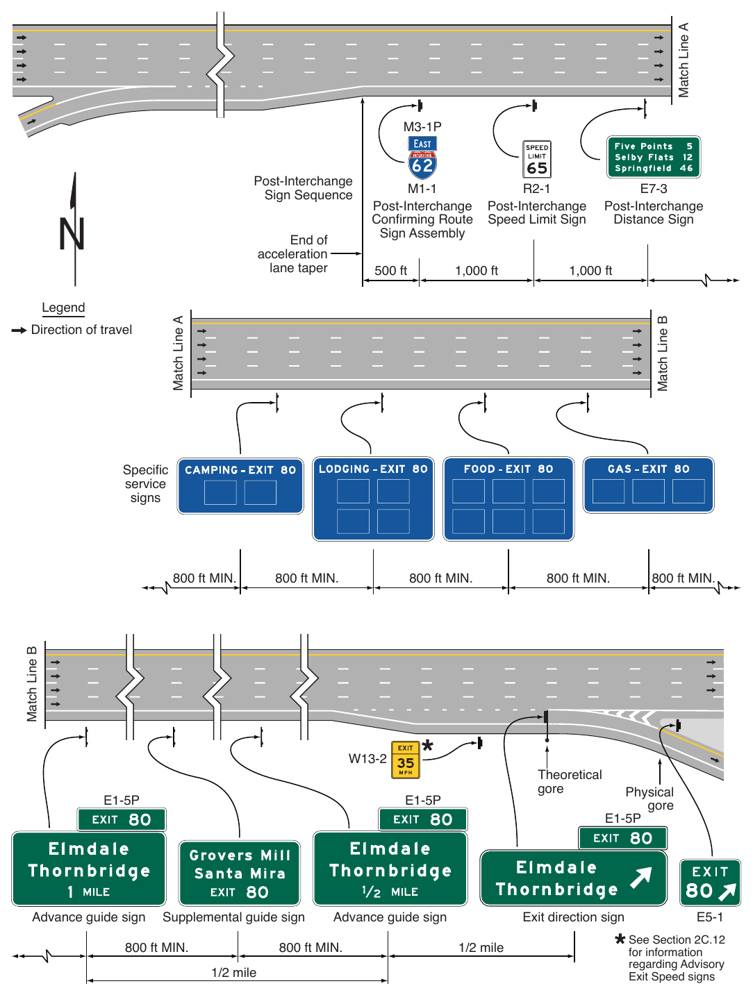
800 ft MIN. 800 ft MIN. 800 ft MIN. 800 ft MIN. Match Line B 800 ft MIN. Theoretical gore Physical gore Advance guide sign Supplemental guide sign 800 ft MIN. 800 ft MIN. 1/2 mile Exit direction sign Advance guide sign 1/2 mile See Section 2C.12 for information regarding Advisory Exit Speed signs Where suffix letters are used for exit numbering, an exit of the same number without a suffix letter shall not be used on the same route in the same direction. For example, if an exit is designated as EXIT 256 A, then there shall not be an exit designated as EXIT 256 on the same route in the same direction.
Guidance
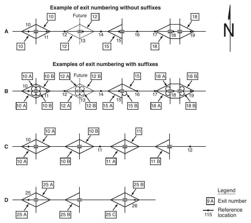
07. To the extent practical, exit numbering should be determined based upon the location of the crossroad with respect to reference location signs as given in the following examples:
- A. If a crossroad intersects the mainline approximately at or after Mile 15 and before Mile 16, the interchange should be designated as EXIT 15 (see Drawings A and B in Figure 2E-3).
- B. If the interchange crossroad is split into two roadways by direction where one direction of the crossroad is downstream of Mile 18 and the other direction is upstream of Mile 18, the interchange exit number should be EXIT 18 (see Drawings A and B in Figure 2E-3).
- C. If there are three closely-spaced interchanges, such as less than 1 mile apart, starting before Mile 16 and ending near or at Mile 17, the interchanges should be designated as EXIT 15, EXIT 16, and EXIT 17.
- D. If there are multiple interchanges so closely spaced together that it is impracticable to designate the exit numbers by the freeway mainline reference mile numbers, suffix letters should be used as provided in this Section (see Drawings C and D in Figure 2E-3).
Option
08. Exit numbers may also be used with Supplemental guide signs in compliance with the provisions of Section 2E.51, and Motorist Service signs in compliance with the provisions of Chapters 2I and 2J.
Standard
09. Where exit suffix letters are used and the number of exits is not equal in both directions of travel, the exit suffix lettering for each direction shall be based on the number of exits in that direction. For example, if in the northbound direction of a freeway there are three exits for Mile 25 and two exits in the southbound direction, the exit numbers northbound shall be EXIT 25 A, EXIT 25 B, and EXIT 25 C; and the exit numbers southbound shall be EXIT 25 B followed by EXIT 25 A (see Drawing D in Figure 2E-3).
10. Except as provided in Section 2E.36 for Collector-Distributor Roadways or as otherwise provided for in this Chapter, exit numbers and suffix letters shall only be used to designate individual exit departure points directly from the freeway mainline. Exit numbers and suffix letters shall not be used for designating ramp splits into two ramps after leaving the mainline.
11. The Exit Number (E1-5P through E1-5eP) plaque shall be positioned above the top right-hand edge of the sign for an exit to the right (see Figure 2E-9).
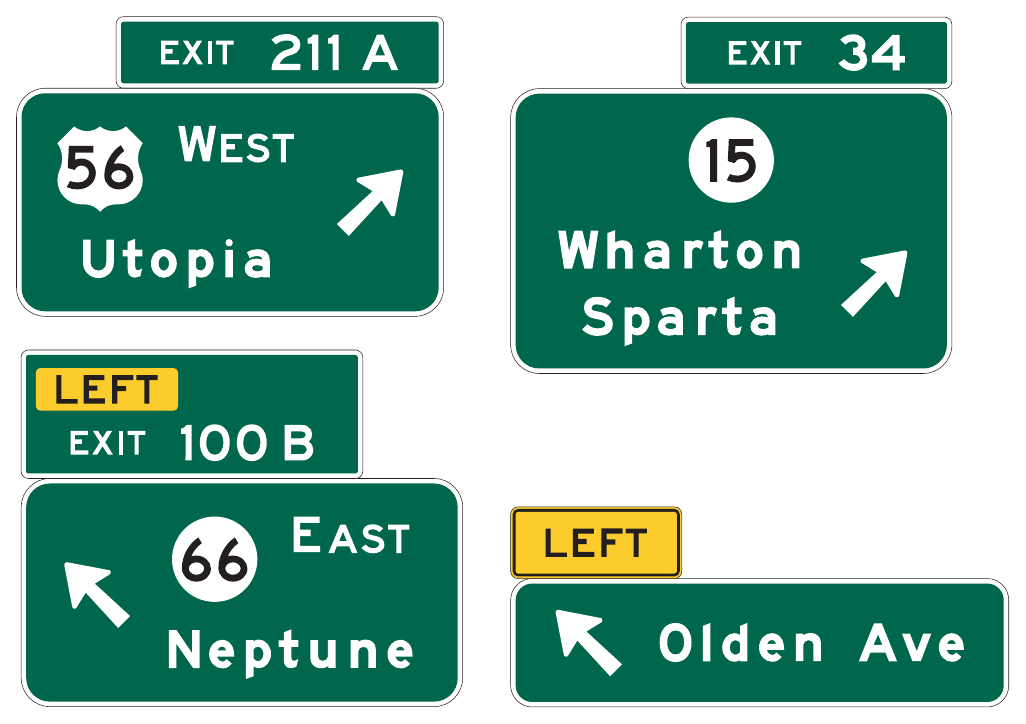
12. Because road users might not expect an exit to the left and might have difficulty in maneuvering to the left, a Left Exit Number (E1-5fP through E1-5kP) plaque (see Figure 2E-9) shall be added above the top left-hand edge of the sign for all numbered left-hand exits (see Figures 2E-18 and 2E-34). The word LEFT on the Left Exit Number plaque shall be a black legend on a yellow rectangular sign panel and shall be centered above the word EXIT.
Support
13. Example Exit Number plaque designs are shown in Figure 2E-9. The incorporation of Exit Number plaques on guide signs is illustrated in Figures 2E-9, 2E-12, 2E-14, 2E-35, and 2E-41.
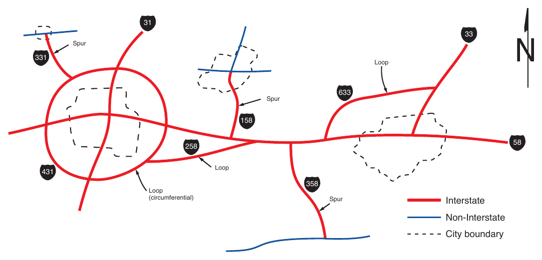
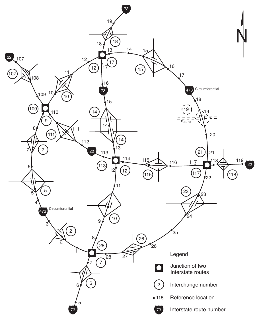
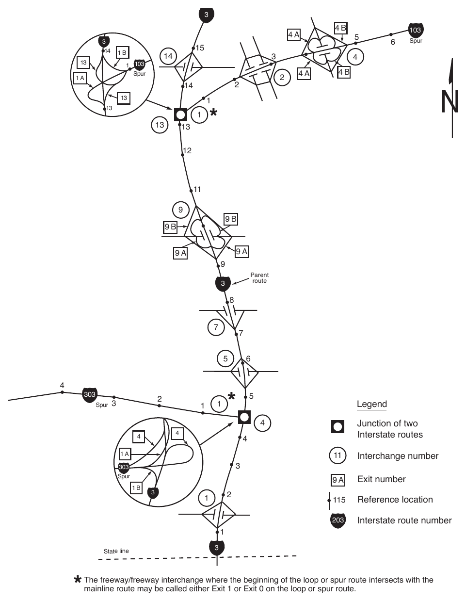
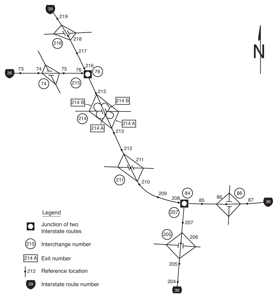
14. Figure 2E-4 provides an example of Interstate route loops and spurs around major metropolitan areas. The general plan for numbering interchange exits is shown in Figures 2E-5 through 2E-8. Figure 2E-5 shows a circumferential route, which is a route that makes a complete circle around a city or town and usually has two interchanges (one on each side of the city or town) with each of the mainline routes that travel through the city or town. Figure 2E-6 shows a loop route, which is a route that departs from a mainline route and then rejoins the same mainline route at a subsequent point downstream. For the purpose of Interstate route numbering, a threedigit Interstate route that provides connectivity between two different Interstate routes is also defined as a loop (see Figure 2E-4). Figure 2E-7 shows a spur route, which is a route that departs from a mainline route and never rejoins the same mainline route. Figure 2E-8 shows two mainline routes that overlap each other.
Standard
15. Regardless of whether a mainline route originates within a State or crosses into the State from an adjacent State, the southernmost or westernmost terminus within that State shall be the beginning point for interchange exit numbering.
16. For circumferential routes, interchange exit numbering shall be in a clockwise direction. The numbering shall begin with the first interchange west of the south end of an imaginary north-south line bisecting the circumferential route, at a radial freeway or other Interstate route, or some other conspicuous landmark in the circumferential route near a south polar location (see Figure 2E-5).
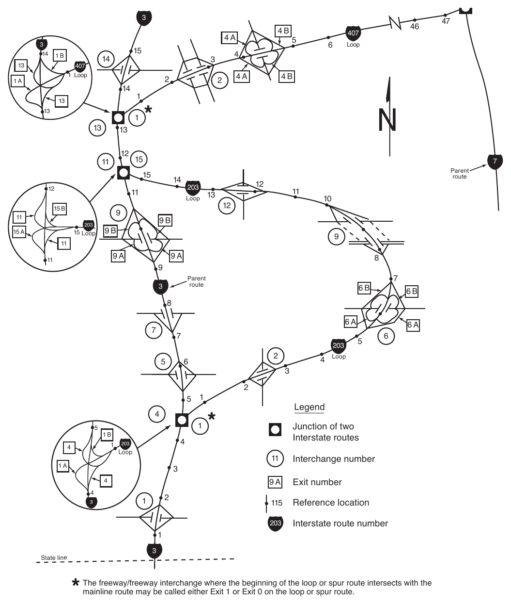
17. The interchange exit numbers on loop routes shall begin at the loop interchange nearest the south or west junction and increase in magnitude toward the north or east junction (see Figure 2E-6).
18. Spur route interchanges shall be numbered in ascending order starting at the interchange where the spur leaves the mainline route (see Figure 2E-7).
19. If a circumferential, loop, or spur route crosses State boundaries, the numbering sequence shall be coordinated by the States to provide continuous interchange exit numbering.
20. Where numbered routes overlap, continuity of interchange exit numbering shall be established for only one of the routes (see Figure 2E-8). If one of the routes is an Interstate and the other route is not an Interstate, the Interstate route shall maintain continuity of interchange exit numbering.
Guidance
21. The route chosen for continuity of interchange exit numbering should also have reference location sign continuity (see Figure 2E-8).
§2E.23 Interchange Advance Guide Signs (E1-1 through E1-3)¶
Support
01. An Interchange Advance guide sign (see Figure 2E-9) gives notice well in advance of the exit point of the principal destinations served by the next interchange and the distance to that interchange.
Standard
02. Except as provided in Paragraph 16 of this Section, and in Paragraph 18 of Section 2E.25, at least one Interchange Advance guide sign shall be used for all interchange classifications.
Guidance
03. At major and intermediate interchanges (see Section 2E.11), at least two Interchange Advance guide signs should be used, placed at ½ mile and at 1 mile in advance of the exit. A third Interchange Advance guide sign should be placed at 2 miles in advance of the exit if spacing permits.
04. At minor interchanges, the Interchange Advance guide sign should be located ½ to 1 mile from the exit gore.
Support
05. Sections 2E.29 through 2E.44 contain additional provisions regarding the number, location, and mounting of Interchange Advance guide signs for certain interchange configurations.
Standard
06. Except as provided in Section 2E.28, the legend on Interchange Advance guide signs shall contain the distance message. For each direction of travel, the legend on the Interchange Advance guide signs shall be the same as the legend on the Exit Direction sign, except that the last line shall be the distance message. The distance message shall read XX MILE(S) where exit numbers are used. Where exit numbers are not used, the distance message shall read EXIT XX MILE(S) for an interchange with one exit ramp, and EXITS XX MILE(S) for an interchange with two or more exit ramps.
Guidance
07. Where an Interchange Advance guide sign is located more than 1,000 feet from the exit, the distance displayed should be to the nearest ¼ mile. Where the distance to be displayed on an Interchange Advance guide sign is 1,000 feet or less, the distance should be displayed in feet, rather than miles, to the nearest 100 feet.
Standard
08. When a distance is displayed in miles, fractions of a mile, rather than decimals, shall be displayed in all cases.
09. For numbered exits, the exit number used with the Interchange Advance guide signs shall be displayed using an Exit Number plaque above and abutting the Interchange Advance guide sign.
10. For numbered exits to the right, an Exit Number (E1-5P through E1-5eP) plaque (see Figure 2E-9) shall be added to the top right-hand edge of the sign.
11. For numbered exits to the left, a Left Exit Number (E1-5fP through E1-5kP) plaque (see Figure 2E-9) shall be added above the top left-hand edge of the sign (see Figures 2E-18 and 2E-34).
12. For unnumbered exits to the left, a LEFT (E1-5mP) plaque (see Figure 2E-9) shall be added to the top left-hand edge of the sign, abutting the sign.
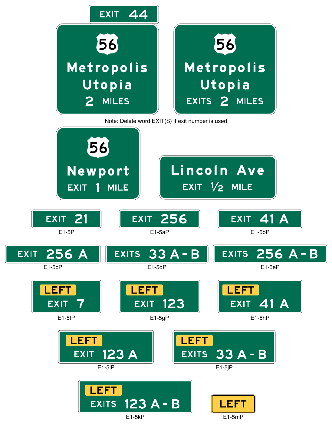
Signs shown: E1-5P, E1-5aP, E1-5bP, E1-5cP, E1-5dP, E1-5eP, E1-5fP, E1-5gP, E1-5hP, E1-5iP, E1-5jP, E1-5kP, E1-5mP
Exit Number Plaques, and LEFT Plaque Note: Delete word EXIT(S) if exit number is used. E1-5aP E1-5eP E1-5dP E1-5cP E1-5fP E1-5gP E1-5hP E1-5jP E1-5iP E1-5kP E1-5bP E1-5mP
Support
13. Section 2E.22 contains additional information regarding exit numbering.
Standard
14. Interchange Advance guide signs for multi-lane exits having an optional exit lane that also carries the through route at major interchanges (see Figures 2E-36, 2E-37, and 2E-42) and for splits with an option lane (see Figures 2E-38 and 2E-39) shall be Overhead Arrow-per-Lane signs designed in accordance with Sections 2E.39 and 2E.40.
Option
15. Where the distance between interchanges is more than 1 mile, but less than 2 miles, the first Interchange Advance guide sign may be closer than 2 miles, but not placed so as to overlap the signing for the preceding exit. Duplicate Interchange Advance guide signs or Interchange Sequence Series signs may be placed in the median on the opposite side of the roadway and are not included in the minimum requirements of interchange signing.
Guidance
16. Where there is less than 800 feet between the theoretical gores of successive interchange entrance or exit ramps, Interchange Sequence Series signs (see Section 2E.24) should be used instead of Interchange Advance guide signs for the affected interchanges.
17. The Interchange Advance guide signs for the last exit from a highway before it becomes a facility on which toll payments are required should include the LAST EXIT BEFORE TOLL (W16-16P) plaque (see Section 2F.10 and Figure 2F-4). The plaque should be installed above the Interchange Advance guide signs, but below the Exit Number or LEFT plaque, if used.
§2E.24 Interchange Sequence Signs (E9-1 and E9-2)¶
Support
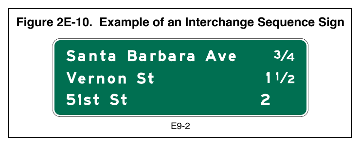
01. Interchanges are sometimes closely spaced, particularly through large urban areas, so that typical guide signs cannot be adequately spaced. In such cases, Interchange Sequence signs identifying the next two (E9-1) or three (E9-2) interchanges (see Figure 2E-10) can provide the necessary exit destination guidance.
Guidance
02. Where there is less than 800 feet between the theoretical gores of successive interchange entrance or exit ramps, Interchange Sequence signs should be used instead of Interchange Advance guide signs for the affected interchanges.
03. If used, Interchange Sequence (E9-1 or E9-2) signs should be used over the entire length of a route in an urban area.
Support
04. Interchange Sequence signs generally supplement Interchange Advance guide signs. Signing of this type is illustrated in Figure 2E-11, and is compatible with the sign spreading concept described in Paragraph 3 of Section 2E.43.
Standard
05. Interchange Sequence signs shall be installed in a series. Interchange Sequence signs shall display the next two or three interchanges by name or route number with distances to the nearest ¼ mile.
06. The first Interchange Sequence sign in the series shall be located in advance of the first Interchange Advance guide sign for the first interchange.
07. Where the exit direction is to the left, a LEFT (E11-2) sign panel (see Figure 2E-17) shall be displayed on the same line immediately to the right of the interchange name or route number.
08. Interchange Sequence signs shall not be substituted for Exit Direction signs.
Guidance
09. Interchange Sequence signs should be located in the median. After the first sign of the series, subsequent Interchange Sequence signs should be placed approximately midway between interchanges.
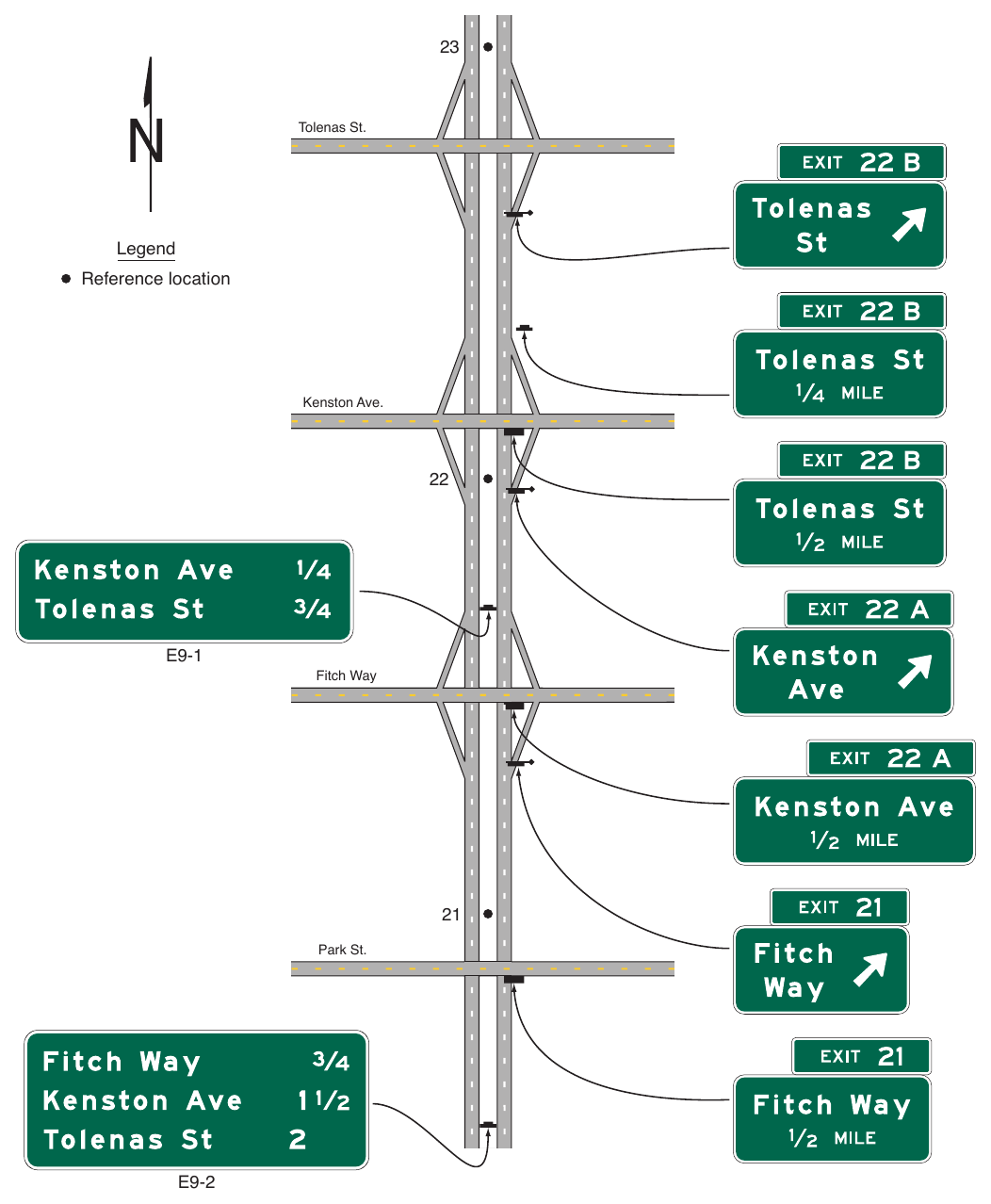
Tolenas St. Legend Reference location Kenston Ave.
22. E9-1 Fitch Way
21. Park St.
Standard
Interchange Sequence signs located in the median shall be installed at overhead sign height (see Section 2A.15).
Option
11. Interchange exit numbers may be displayed to the left of the interchange name or route number.
§2E.25 Exit Direction Signs (E4 Series)¶
Support
01. The Exit Direction sign (see Figure 2E-12) repeats the route and destination information that was displayed on the Interchange Advance guide sign(s) for the next exit, and thereby assures road users of the destination served and indicates whether they exit to the right or left for that destination.
Standard
02. Exit Direction signs shall be used at major and intermediate interchanges. Populations or other similar information shall not be displayed on Exit Direction signs.
Guidance
03. Exit Direction signs should be used at minor interchanges (see Section 2E.30).
Support
04. Sections 2E.28, 2E.30, 2E.31, 2E.33 through 2E.35, 2E.38, and 2E.40 through 2E.42 illustrate the use, location, and mounting of Exit Direction signs for certain interchange configurations. The placement location of the Exit Direction sign at the interchange depends on the type of mounting, post-mounted or overhead, and whether there is a deceleration lane (see Figure 2E-13).
Guidance
05. When post-mounted, the Exit Direction sign should be installed at the beginning of the deceleration lane taper. When mounted overhead, the Exit Direction sign should be installed over the exiting lane in the vicinity of the theoretical gore. If there is less than 300 feet from the beginning of the taper to the theoretical gore, the Exit Direction sign should be installed overhead (see Figure 2E-13).
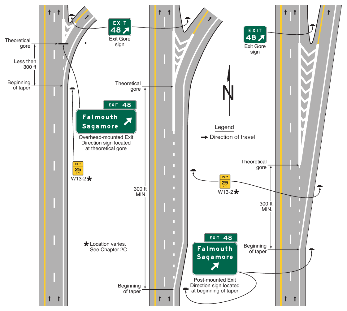
Signs shown: W13-2
Location varies. See Chapter 2C. Beginning of taper Beginning of taper Post-mounted Exit Direction sign located at beginning of taper
Standard
Except where Overhead Arrow-per-Lane guide signs are used (see Sections 2E.40 and 2E.42, and Paragraph 7 of this Section), where a through lane is being terminated (dropped) at an exit, the Exit Direction sign shall be placed overhead at the theoretical gore (see Figures 2E-18, 2E-19, 2E-33, 2E-42, and 2E-46).
07. Except as provided in Paragraph 4 of Section 2E.40, where Overhead Arrow-per-Lane guide signs are used for the Interchange Advance guide sign(s) for a multi-lane exit having an optional exit lane that also carries the through route or for a split with an option lane, an Overhead Arrow-per-Lane guide sign shall also be used instead of the Exit Direction sign and located near, but not downstream from, the point where the outside edge of the dropped lane begins to diverge from the main roadway (see Figures 2E-36 through 2E-38). The Overhead Arrow-per-Lane guide sign shall be designed in accordance with the provisions of Section 2E.40.
08. The following provisions shall govern the design and application of overhead Exit Direction signs:
- A. The sign shall display the Exit Number plaque (if exit numbering is used), the route number, cardinal direction, and destination, as applicable, with a diagonally upward-pointing directional arrow (see Figure 2E-12).
- B. The message EXIT ONLY in black on a yellow sign panel (E11-1d or E11-1e) shall be used on the overhead Exit Direction sign to advise road users of a lane drop situation (see Figures 2E-18, 2E-19, 2E-42, and 2E-44). The sign shall comply with the provisions of Section 2E.28.
09. For numbered exits to the right, an Exit Number (E1-5P through E1-5eP) plaque (see Figure 2E-9) shall be added above the top right-hand edge of the sign.
10. For numbered exits to the left, a Left Exit Number (E1-5fP through E1-5kP) plaque (see Figure 2E-9) shall be added above the top left-hand edge of the sign.
11. For unnumbered exits to the left, a LEFT (E1-5mP) plaque (see Figure 2E-9) shall be added above the top left-hand edge of the sign.
Support
12. Section 2E.22 contains additional information regarding exit numbering.
Guidance
13. At multi-exit interchanges, the Exit Direction sign should be located directly over the exiting lane for the first exit, in accordance with this Section. An Interchange Advance guide sign for the second exit should be installed at the same location, normally over the right-hand through lane. Only for those conditions where the through movement is not evident should a confirmatory message (a Pull-Through sign as shown in Figure 2E-16) be used over the left-hand lane(s) to guide road users traveling through an interchange (see Section 2E.43 for additional information on sign spreading).
14. Where the freeway or expressway is on an overpass, the Exit Direction sign for the second exit should be installed on an overhead support over the exit lane in advance of the gore point, as near as practicable to the theoretical gore. Where the freeway or expressway passes under the crossroad and the exit ramp is located beyond the overcrossing structure, the overhead Exit Direction sign for the second exit should be placed either on the overcrossing structure (see Figures 2E-29 through 2E-31) or on a separate structure located immediately in front of the overcrossing structure.
Option
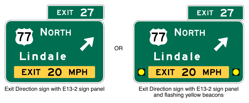
15. Where extra emphasis of an especially low advisory ramp speed is needed, an Exit Direction Advisory Speed (E13-2) sign panel (see Figure 2E-14) may be placed at the bottom of the Exit Direction sign to supplement, but not to replace, the exit or ramp advisory speed warning signs.
16. Warning Beacons in compliance with Paragraph 17 of this Section may be used with the E13-2 sign panel.
Standard
17. Where Warning Beacons are used in conjunction with the E13-2 sign panel within a guide sign (see Figure 2E-14), the nearest edges of the beacons shall be placed at least 12 inches from the edges of the E13-2 sign panel, from the edges of the guide sign, and from any other legend within the guide sign. The design and operation of Warning Beacons shall otherwise comply with the provisions of Chapter 4S of this Manual.
Signs shown: E13-2
Option
18. In cases, where sight distance is restricted because of structures or unusual alignment, principally in urban areas, making it impossible to locate the Exit Direction sign without violating the required minimum spacing between major guide signs (see Section 2E.23), Interchange Sequence signs (see Section 2E.24) may be substituted for an Interchange Advance guide sign.
Guidance
19. At the last exit from a highway before it becomes a facility on which toll payments are required, the LAST EXIT BEFORE TOLL (W16-16P) plaque (see Section 2F.10 and Figure 2F-4) should be installed above the Exit Direction sign, but below the Exit Number or LEFT plaque, if used.
§2E.26 Exit Gore Signs and Plaque (E5-1 Series)¶
Support
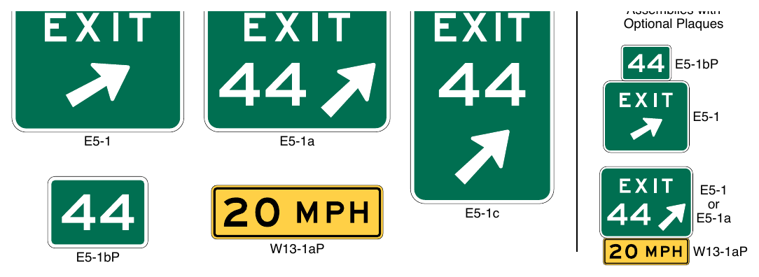
01. The Exit Gore sign (see Figure 2E-15) in the gore indicates the exiting point or the place of departure from the main roadway. Consistent application of this sign at each exit is important to provide adequate visibility of the departure of the exit roadway from the main roadway.
Standard
02. The gore shall be defined as the area located between the main roadway and the ramp just beyond where the ramp branches from the main roadway. An Exit Gore sign shall be located in the gore for each ramp that departs from the main roadway of a freeway or expressway, or departs from a collector-distributor roadway, and shall display the word EXIT (E5-1) if interchange exit numbering is not used or EXIT XX (E5-1a or E5-1c) if interchange exit numbering is used, and an appropriate diagonally upward-pointing arrow. If suffix letters are used for exit numbering at a multi-exit interchange, the suffix letter shall also be included on the Exit Gore (E5-1a or E5-1c) sign or Exit Gore Number (E5-1bP) plaque and shall be separated from the exit number by a space having a width of between ½ and ¾ of the height of the suffix letter. Breakaway or yielding supports shall be used.
Guidance
03. The arrow should be aligned to approximate the angle of departure. Each gore should be treated similarly, whether the interchange has one exit roadway or multiple exits.
Option
04. The Narrow Exit Gore (E5-1c) sign (see Figure 2E-15) may be used in gore areas of limited width where the width of the Exit Gore (E5-1a) sign would not permit sufficient lateral offset (see Section 2A.16), such as for ramp departures that are nearly parallel to the main roadway where the Exit Gore sign would be mounted on a narrow island or barrier. Where the E5-1c sign is mounted at a height of 14 feet or more from the roadway, the directional arrow may point diagonally downward.
Guidance
05. The E5-1c sign should not be used in gore areas where an E5-1a sign could be installed with sufficient lateral offset.
Option
06. Where extra emphasis of an especially low advisory ramp speed is needed, the Confirmation Advisory Speed (W13-1aP) plaque (see Section 2C.59) indicating the advisory speed may be mounted below the Exit Gore sign (see Figure 2E-15) to supplement, but not to replace, the exit or ramp advisory speed warning signs.
07. To improve the visibility of the gore for exiting drivers, a Type 1 object marker (see Chapter 2C) may be installed 4 feet above the ground line on each sign support below the Exit Gore sign.
08. An Exit Gore Number (E5-1bP) plaque (see Figure 2E-15) may be installed above an existing Exit Gore (E5-1) sign when an unnumbered exit is converted to a numbered exit until such time as an E5-1 sign is being replaced for other reasons (see Paragraph 9 of this Section).
Standard
09. An Exit Gore (E5-1a) sign shall be used when the replacement of an existing assembly of an E5-1 sign and E5-1bP plaque becomes necessary.
§2E.27 Pull-Through Signs (E6-1 Series and E6-2 Series)¶
Support
01. Pull-Through (E6-1 series and E6-2 series) signs (see Figure 2E-16) are overhead guide signs intended for through traffic.
Guidance
02. Pull-Through signs should be used where the geometrics of a given interchange are such that it is not clear to the road user as to which is the through roadway, or where additional route guidance is desired. Pull-Through signs with down arrows should be used where the alignment of the through lanes is curved and the exit direction is straight ahead, where the number of through lanes is not readily evident, and at multi-lane exits where there is a reduction in the number of through lanes. Pull-Through signs should not be used at exits with option lanes where full-width Overhead Arrow-per-Lane signs are being used.
Standard
03. When used, Pull-Through signs shall display the route shield and the cardinal direction for the through route.
Option
04. Pull-Through signs may display the control city and down arrows (see Figure 2E-16 and Section 2E.18).
Support
05. Sections 2E.28, 2E.39, and 2E.40 contain information regarding the use of Overhead Arrow-per-Lane guide signs at multi-lane exits where there is a reduction in the number of through lanes and a through lane becomes an interior option lane for through or exiting traffic.
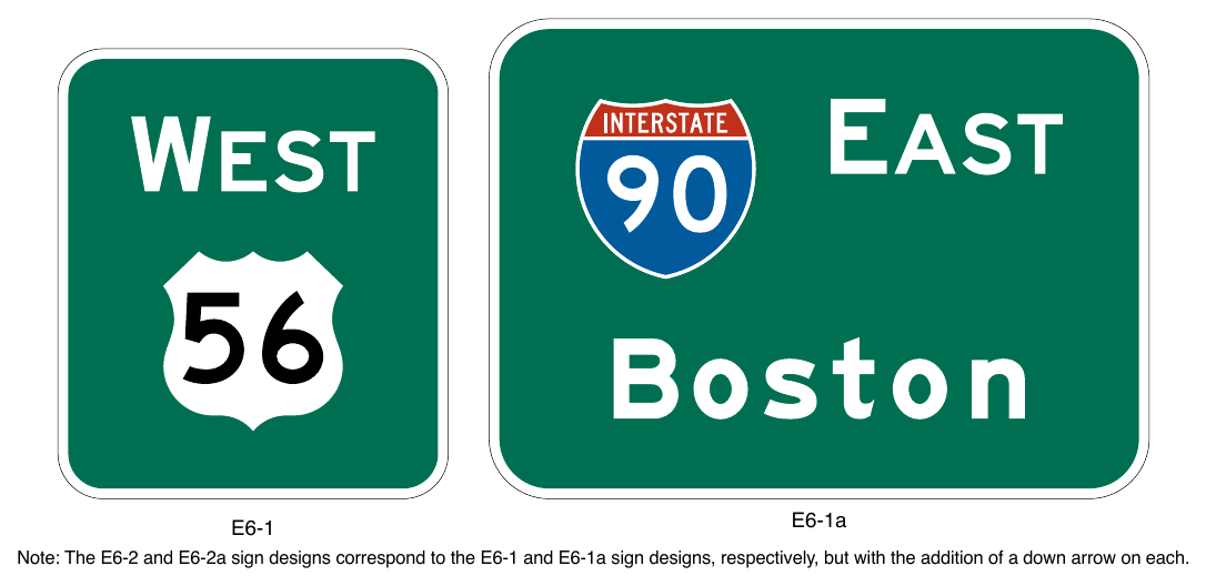
Note: The E6-2 and E6-2a sign designs correspond to the E6-1 and E6-1a sign designs, respectively, but with the addition of a down arrow on each.
§2E.28 Signing for Interchange Lane Drops without an Optional Exit Lane¶
Standard
01. The provisions of this Section shall only apply to lane drops at exits that do not have an optional exit lane. At exits that have an optional exit lane in addition to the dropped lane, the provisions of Sections 2E.39, 2E.40, and 2E.42 shall apply.
02. Except as provided in Paragraph 14 of this Section, major guide signs for all lane drops at interchanges shall be mounted overhead. An EXIT ONLY sign panel shall be used for all interchange lane drops at which the through route is carried on the main roadway.
03. Except on Overhead Arrow-per-Lane and Diagrammatic Advance guide signs (see Sections 2E.39 through 2E.41), the EXIT ONLY (down arrow) (E11-1 or E11-1f) sign panel (see Figure 2E-17) shall be used on all overhead Advance guide signs of lane drops (see Figures 2E-18, 2E-19, and 2E-34). The number of arrows on each sign shall correspond to the number of dropped lanes at the location of each sign. Placement of the down arrow shall comply with the provisions of Section 2E.18.
04. For lane drops, the bottom portion of the overhead Exit Direction sign shall be yellow with a black border and shall include a diagonally upward-pointing black directional arrow (left or right, as appropriate) for each lane dropped at the exit (see Figures 2E-18 and 2E-19). The sign shall be designed and placed so that each arrow is located over the approximate center of each lane being dropped. Except as provided in Paragraph 5 of this Section, the words EXIT and ONLY shall be positioned to the left and right, respectively, of the arrow on the E11-1d sign panel (see Figure 2E-17) for a single-lane drop. For a two-lane drop, the words EXIT ONLY shall be located between the two arrows on the E11-1e sign panel (see Figure 2E-17). The number of arrows on the sign shall correspond to the number of dropped lanes at the location of the sign.
Option
05. Where an existing sign structure length or adjacent signs constrain the width or placement of the Interchange Advance guide sign on that structure, the down arrow may be positioned to the right or left of the words EXIT ONLY, instead of between the words, to allow for the positioning of the arrow over the approximate center of the lane. Where the width of the Exit Direction sign extends over the adjacent lane, the directional arrow may be placed to the right of the words EXIT ONLY for an exit to the right, or to the left of the words EXIT ONLY for an exit to the left, to allow for the positioning of the arrow over the dropped lane.
06. EXIT ONLY messages of either the combination of E11-1a and E11-1b, or the E11-1c sign panels (see Figure 2E-17) may be used to retrofit existing signing to warn of a lane drop situation ahead.
Standard
07. If used to retrofit an existing guide sign, the E11-1a and E11-1b sign panels (see Figure 2E-17) shall be placed on either side of a white down arrow on an Interchange Advance guide sign and on either side of a white directional arrow on an Exit Direction sign. The E11-1c sign panel (see Figure 2E-17), if used to retrofit an existing Interchange Advance guide sign, shall be placed between the lower destination message and the white down arrow.
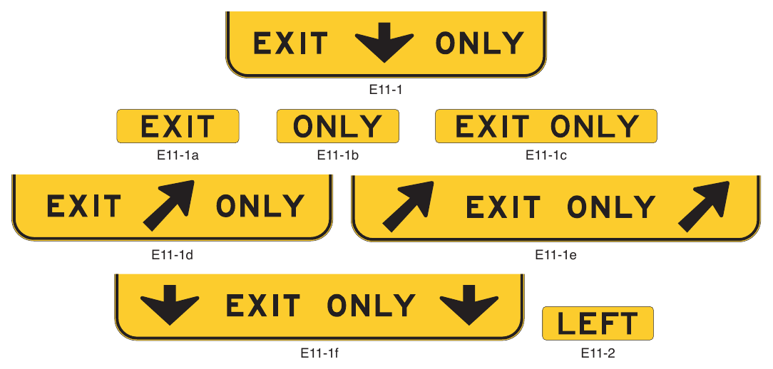
Signs shown: E11-1, E11-1a, E11-1b, E11-1c, E11-1d, E11-1e, E11-1f, E11-2
Guidance
08. Except as provided in Paragraph 9 of this Section for an auxiliary lane, Interchange Advance guide signs for lane drops within 1 mile of the interchange should not display the distance message.
09. Where the dropped lane is an auxiliary lane that is provided between successive entrance and exit ramps of two separate interchanges and the distance between the two ramps is less than 1 mile, the first Interchange Advance guide sign in the sequence downstream from the entrance ramp should display the distance message (see Figures 2E-20 and 2E-21).
10. Where the dropped lane carries the through route, signs should be used without the EXIT ONLY sign panel.
Support
11. Figures 2E-20 and 2E-21 show examples of guide signs for a dropped auxiliary lane between separate interchanges using overhead and post-mounted guide signs, respectively. Figure 2E-22 shows guide signs used for an auxiliary lane that is ½ mile or longer.
12. Sections 2E.39 through 2E.42 contain information on the signing of lane drops at exits that also have an option lane.
13. Section 2B.31 contains information regarding regulatory signs that can also be used for freeway lane drop situations and Section 2C.50 contains information regarding warning signs that can also be used for freeway lane drop situations.
Guidance
14. In limited cases in which conditions are so constrained that it is impossible to locate an Interchange Advance guide sign either overhead or partly over the dropped lane, precluding positioning of the down arrow as provided in Paragraph 3 of this Section, a sign panel displaying the legend RIGHT (LEFT) LANE ONLY in a black legend on a yellow background should be substituted for the EXIT ONLY panel on that sign. In such cases, the Interchange Advance guide signs should be alternated with RIGHT (LEFT) LANE FOR EXIT ONLY (W9-7) signs (see Section 2C.50).
15. Where a mainline lane is terminated immediately after an exit ramp, overhead and/or post mounted warning signs should be used to warn traffic as shown in Figure 2E-23.
§2E.29 Signing by Type of Interchange¶
Support
01. Road users need signs to help identify the location of the exit, as well as to obtain route, direction, and destination information for specific exit ramps. Figures 2E-26 through 2E-33 show examples of guide signs for common types of interchanges. The interchange layouts shown in most of the figures illustrate only the major guide signs for one direction of traffic on the freeway and on the exit ramps. Section 2D.49 contains information regarding the signing of the crossroad approaches and connecting roadways to freeways and expressways.
Guidance
02. The signing layout for all interchanges of the same type should be similar. For the purpose of uniform application, the significant features of the signing layout for each of the more frequent types of interchanges (illustrated in Figures 2E-26 through 2E-33) should be followed as closely as possible. Even when unusual geometric features exist, variations in signing layout should be held to a minimum.
03. Where a single interchange combines a different type of ramp configuration for each direction of travel, the main roadway major guide signing should be determined by the specific interchange type for that direction of travel.
Support
04. Figure 2E-24 shows an example of signing for a complex interchange that combines intermediate interchange ramps within a major interchange.
05. Figure 2E-25 shows an example of signing for an interchange exit ramp with a downstream split.
§2E.30 Minor Interchange¶
Option
01. Less signing may be used for minor interchanges because such interchanges customarily serve low volumes of mostly local traffic.
Support
02. An example of guide signs for a minor interchange is shown in Figure 2E-26.
Standard
03. In accordance with the provisions of Sections 2E.23 and 2E.26, at least one Interchange Advance guide sign and an Exit Gore sign shall be used at a minor interchange.
Guidance
04. An Exit Direction sign in compliance with Section 2E.25 should also be used.
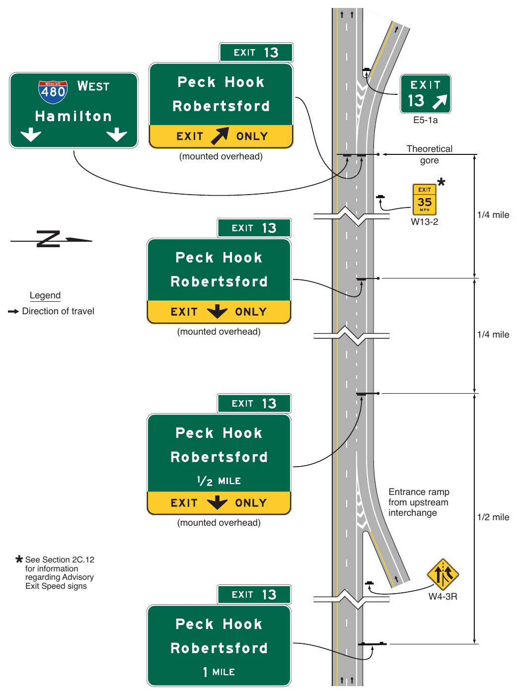
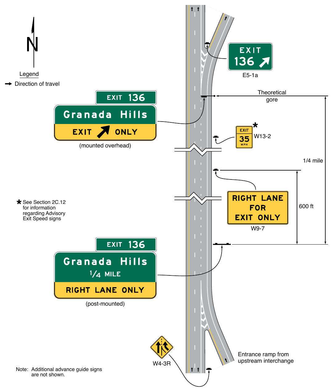
(mounted overhead) 1/4 mile See Section 2C.12 for information regarding Advisory Exit Speed signs 600 ft (post-mounted) Note: Additional advance guide signs are not shown. Entrance ramp from upstream interchange
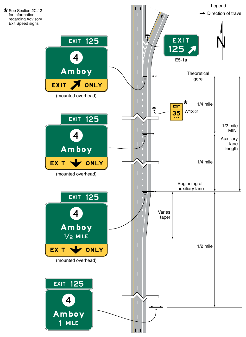
(mounted overhead) 1/4 mile 1/2 mile Auxiliary lane length 1/4 mile (mounted overhead) Beginning of auxiliary lane Varies taper 1/2 mile (mounted overhead)
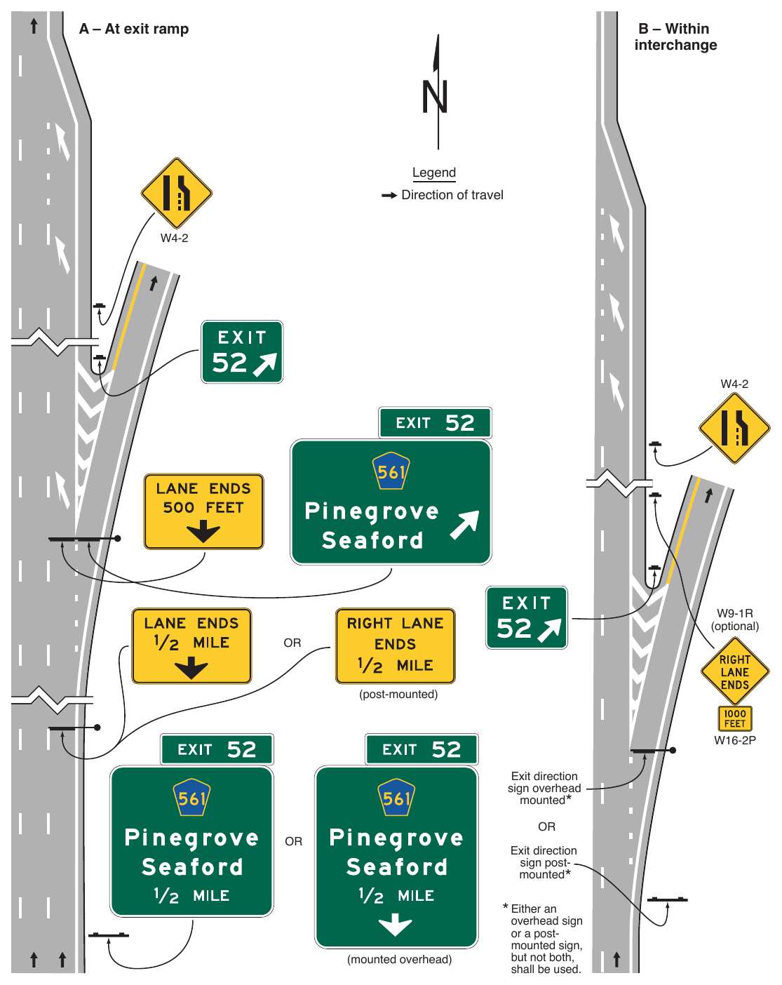
sign post-mounted* (mounted overhead) overhead sign or a post-mounted sign, but not both, shall be used. Scale = .75% borders checked Page 329- kal Woodm o re Roa d
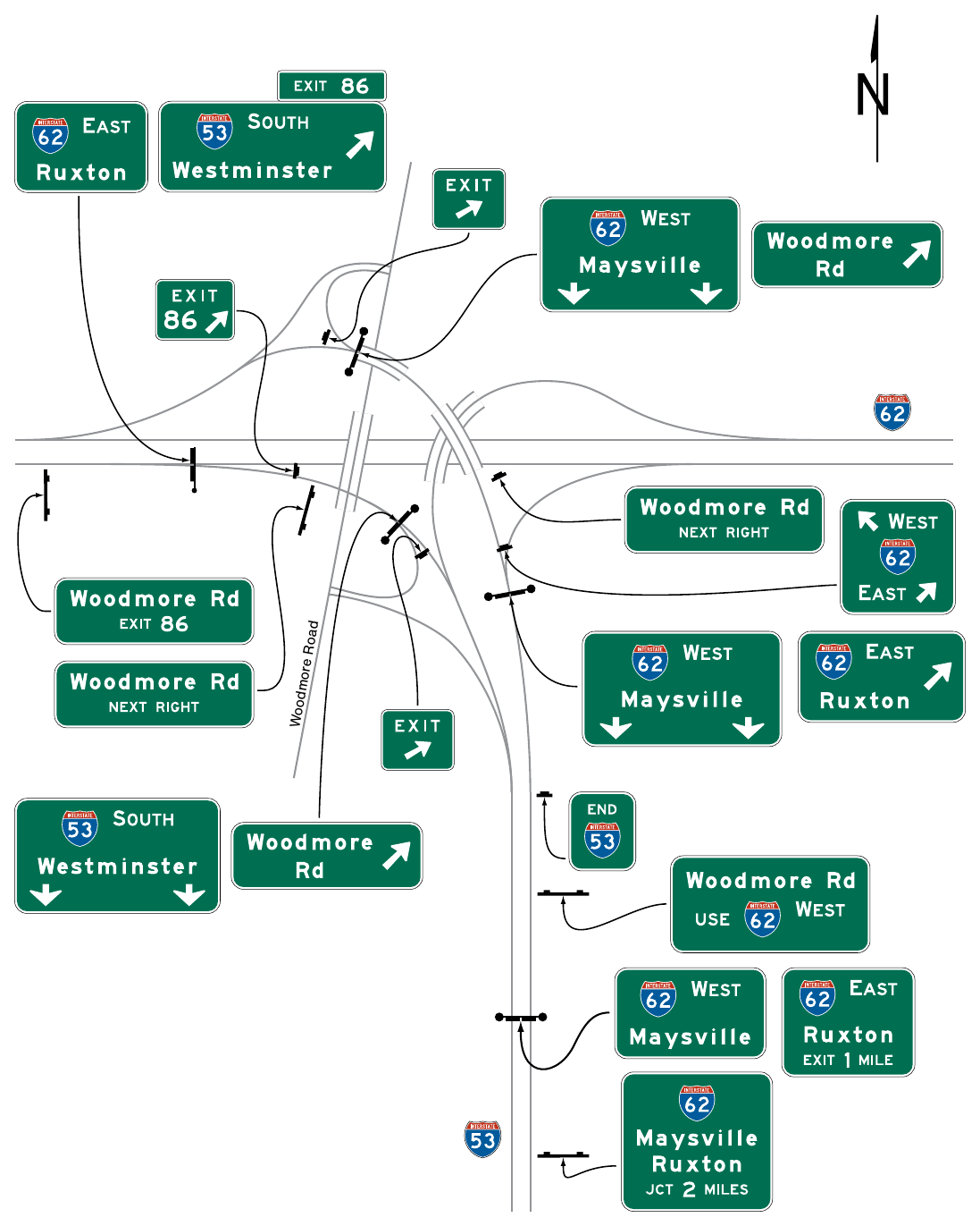
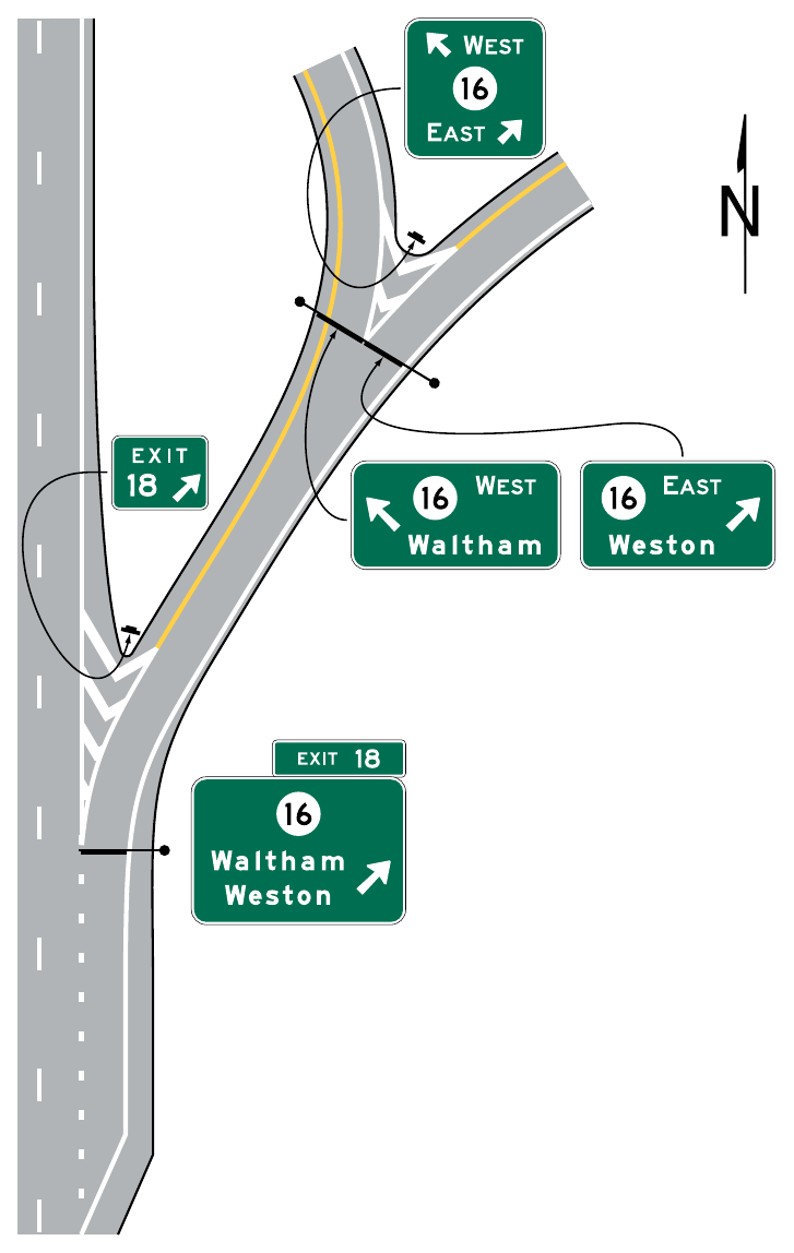
with a Downstream Split (Sheet 1 of 2)
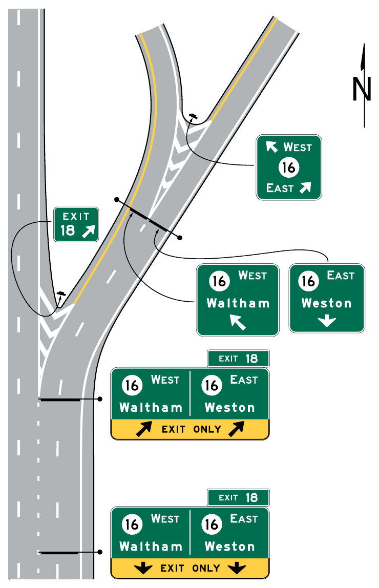
with a Downstream Split (Sheet 2 of 2)
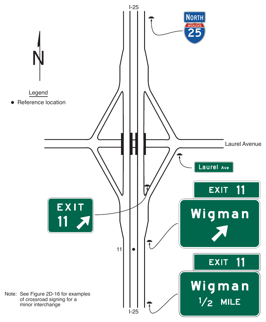
Note: See Figure 2D-16 for examples of crossroad signing for a minor interchange
§2E.31 Diamond Interchange¶
Support
01. An example of guide signs for a diamond interchange is shown in Figure 2E-27.
02. The typical diamond interchange ramp departs from the main roadway such that a speed reduction generally is not necessary in order for a driver to negotiate an exit maneuver from the main roadway onto the ramp roadway. Section 2C.12 contains provisions for the use of an Advisory Exit Speed (W13-2) sign for situations where a speed reduction is necessary.
Guidance
03. When a speed reduction is not necessary, an Advisory Exit Speed sign should not be used.
04. The Advisory Exit Speed sign, if used, should be located along the deceleration lane or along the ramp such that it is visible to the driver far enough in advance to allow the driver to decelerate before reaching the curve associated with the exiting maneuver. Use and placement of the Advisory Exit Speed sign should otherwise comply with Section 2C.12 of this Manual.
Option
05. A Stop Ahead (W3-1) or Signal Ahead (W3-3) warning sign (see Section 2C.35) may be placed, where engineering judgment indicates a need, along the ramp in advance of the crossroad, to give notice to the driver.
Guidance
06. When used on two-lane ramps, Stop Ahead or Signal Ahead signs should be used in pairs with one sign on each side of the ramp.
07. Where the exit ramp allows traffic to turn in either direction onto the crossroad, a Destination (D1 series) sign (see Section 2D.36) that includes each destination displayed on the Advance, Exit Direction, and Supplemental guide signs along the main roadway for that exit should be placed along the ramp.
§2E.32 Diamond Interchange in Urban Area¶
Support
01. An example of guide signs for a diamond interchange in an urban area is shown in Figure 2E-28. This example includes the use of the Community Interchanges Identification sign (see Section 2E.52), which might be useful if two or more interchanges serve the same community.
02. In urban areas, street names are often displayed as the principal message in destination signs.
Option
03. If interchanges are too closely spaced to locate the Interchange Advance guide signs at the distances specified in Section 2E.23, they may be placed closer to the exit with the distances displayed adjusted accordingly.
§2E.33 Cloverleaf Interchange¶
Support
01. A cloverleaf interchange has two exits for each direction of travel. The exits are closely spaced and have common Advance guide signs. An example of guide signs for a cloverleaf interchange is shown in Figure 2E-29.
Guidance
02. The Advance guide signs should include two place names, one corresponding to each exit ramp, with the name of the place served by the first exit on the upper line.
Standard
03. An overhead guide sign assembly shall be placed at the theoretical gore of the first exit ramp, with an Exit Direction sign for the first exit and an Interchange Advance guide sign for the second exit, as shown in Figure 2E-29. The second exit shall be indicated by an overhead Exit Direction sign over the auxiliary lane.
04. Interchanges with more than one exit from the main roadway shall be numbered as described in Section 2E.22 with an appropriate suffix.
05. Diagrammatic Advance signs shall not be used for cloverleaf interchanges except as otherwise provided in Section 2E.41.
Guidance
06. Where the main roadway passes under the crossroad and the exit roadway is located beyond the overcrossing structure, the placement of the overhead Exit Direction sign for the second exit should comply with Section 2E.25 (see Figure 2E-29).
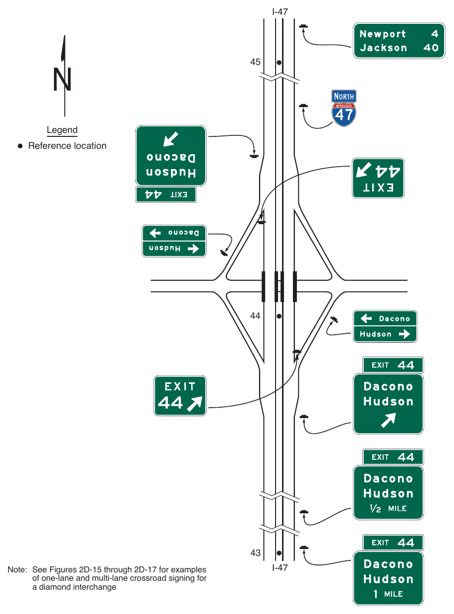
Note: See Figures 2D-15 through 2D-17 for examples of one-lane and multi-lane crossroad signing for a diamond interchange
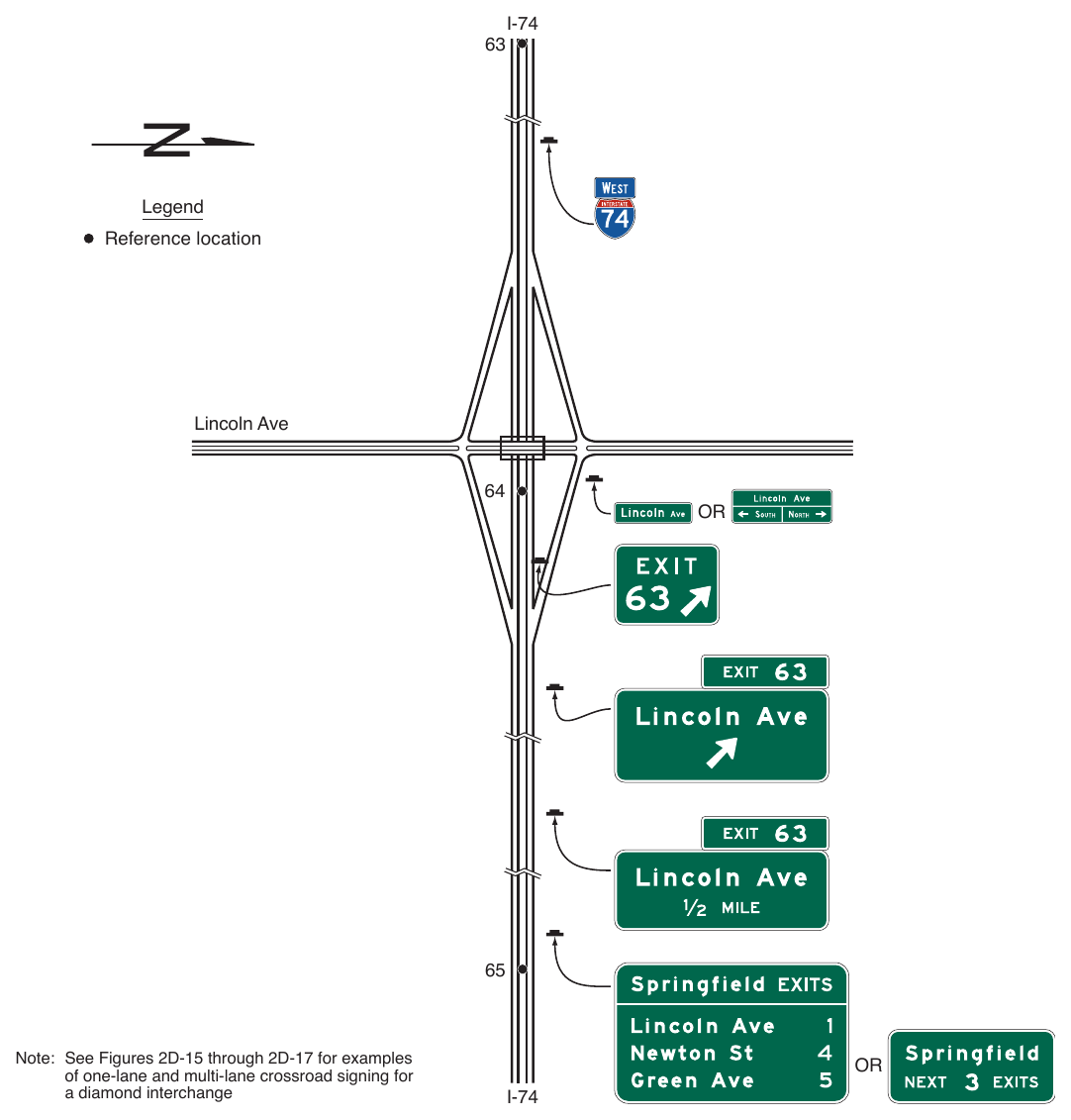
Note: See Figures 2D-15 through 2D-17 for examples of one-lane and multi-lane crossroad signing for a diamond interchange
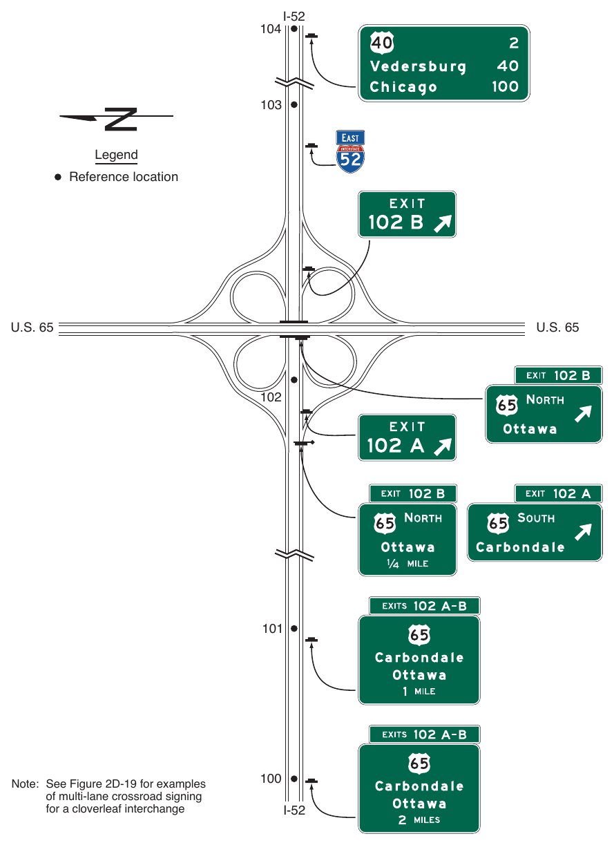
Note: See Figure 2D-19 for examples of multi-lane crossroad signing for a cloverleaf interchange
§2E.34 Cloverleaf Interchange with Collector-Distributor Roadways¶
Support
01. An example of guide signs for a full cloverleaf interchange with collector-distributor roadways is shown in Figure 2E-30.
Guidance
02. Destination names and route numbers shown on the collector-distributor roadway signing should be the same as those used on the upstream Interchange Advance guide signs on the main roadway.
Standard
03. Exit Direction signs at exits from the collector-distributor roadways shall be overhead and located at the theoretical gore of the collector-distributor roadway and the exit ramp.
Guidance
04. Exits from the collector-distributor roadways should be numbered with an appropriate suffix. If the exits from a collector-distributor roadway are numbered, the Interchange Advance guide and Exit Direction signs on the main roadway should include, in addition to two place names, their corresponding exit number and suffixes with the plural EXITS in the Exit Number (E1-5P series) plaque. If only the exit from the main roadway is numbered, the Interchange Advance guide and Exit Direction signs on the main roadway should use the singular EXIT in the Exit Number plaque. If interchange exit numbering is not used, the Interchange Advance guide signs on the main roadway should use the singular EXIT in the distance messages.
§2E.35 Partial Cloverleaf Interchange¶
Support
01. An example of guide signs for a partial cloverleaf interchange is shown in Figure 2E-31.
Guidance
02. For a partial cloverleaf with only one exit roadway in a direction of travel, where the main roadway passes under the crossroad and the exit roadway is located beyond the overcrossing structure, the overhead Exit Direction sign should be placed either on the overcrossing structure (see Figure 2E-31) or on a separate structure located immediately in front of the overcrossing structure.
Support
03. Partial cloverleaf interchanges with successive exit ramps from the same direction of travel are signed the same as cloverleaf interchanges for that direction of travel (see Section 2E.33).
§2E.36 Collector-Distributor Roadways for Successive Interchanges¶
Support
01. Examples of guide signs for a collector-distributor roadway that provides access to multiple interchanges are shown in Figure 2E-32. Section 2J.09 contains provisions for General Service and Specific Service signs.
Guidance
02. Where access to successive interchanges is provided from a single collector-distributor roadway, the number of lines of destination information displayed on the major guide signs on the main roadway approach to the collector-distributor roadway should comply with the provisions of Section 2E.15. Where additional destinations are displayed on the main roadway, those destinations should be displayed on Supplemental guide signs (see Section 2E.51) on the approach to the collector-distributor roadway.
03. Where exit numbering is used, the exit numbers for exits accessed from the collector-distributor roadway should be displayed on the main roadway guide signs.
04. An Exit Gore sign (see Section 2E.26) should be placed in the gore where the collector-distributor roadway departs from the main roadway.
05. Interchange guide signing along the collector-distributor roadway should comply with the provisions for interchange signing in this Chapter.
§2E.37 Freeway-to-Freeway Interchanges¶
Support
01. Freeway-to-freeway interchanges are major decision points where the effect of taking a wrong ramp cannot be easily corrected. Reversing direction on the connecting freeway or reentering to continue on the intended course is usually not possible. Examples of guide signs for freeway-to-freeway interchanges are shown in Figure 2E-33.
Guidance
02. The sign messages should contain only the route shield, cardinal direction, and the name of the next control city on the route. Arrows should point as indicated in Section 2D.08, except where Overhead Arrow-per-Lane or Diagrammatic Advance signs are used in accordance with the provisions of Sections 2E.39 through 2E.41.
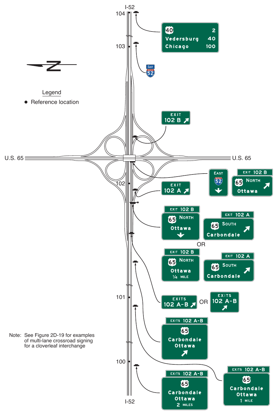
Note: See Figure 2D-19 for examples of multi-lane crossroad signing for a cloverleaf interchange
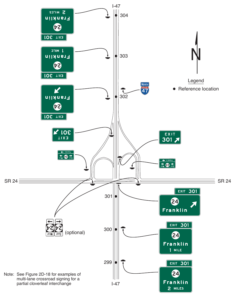
Note: See Figure 2D-18 for examples of multi-lane crossroad signing for a partial cloverleaf interchange
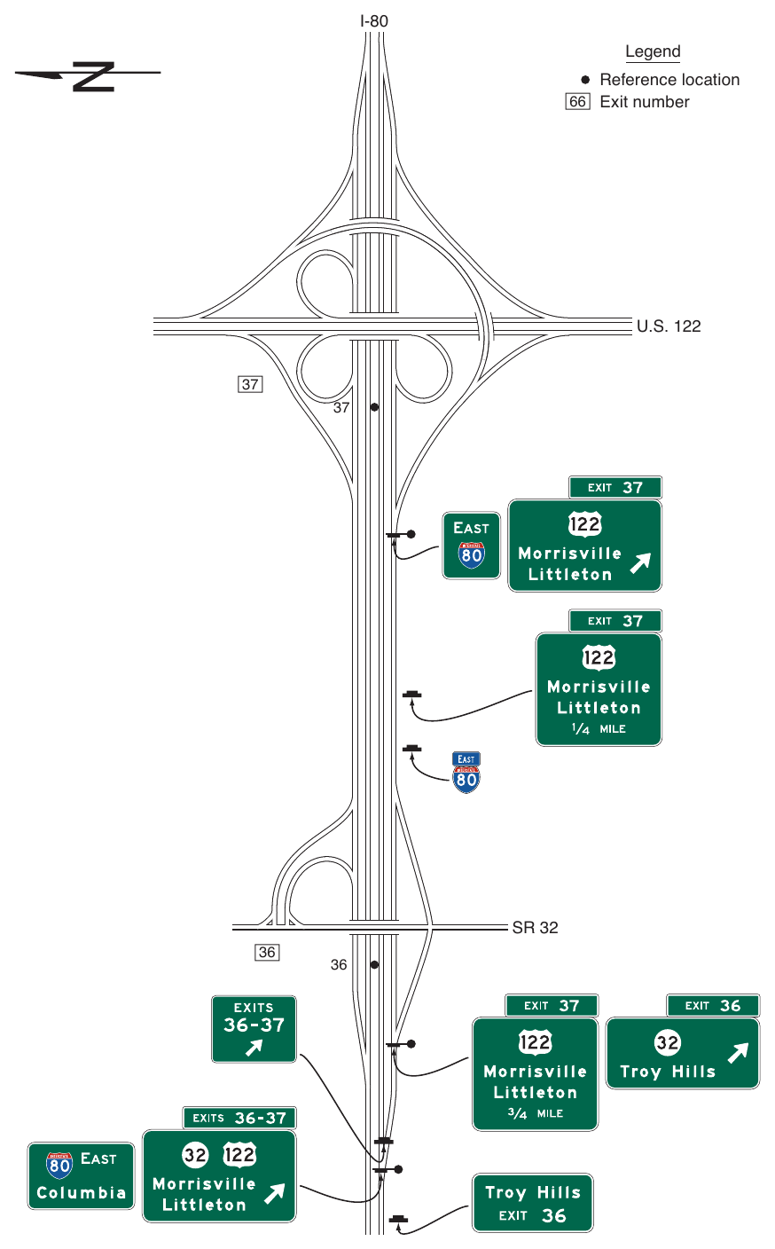
with Collector-Distributor Roadways (Sheet 1 of 2) Legend Reference location 66 Exit number
37. SR 32
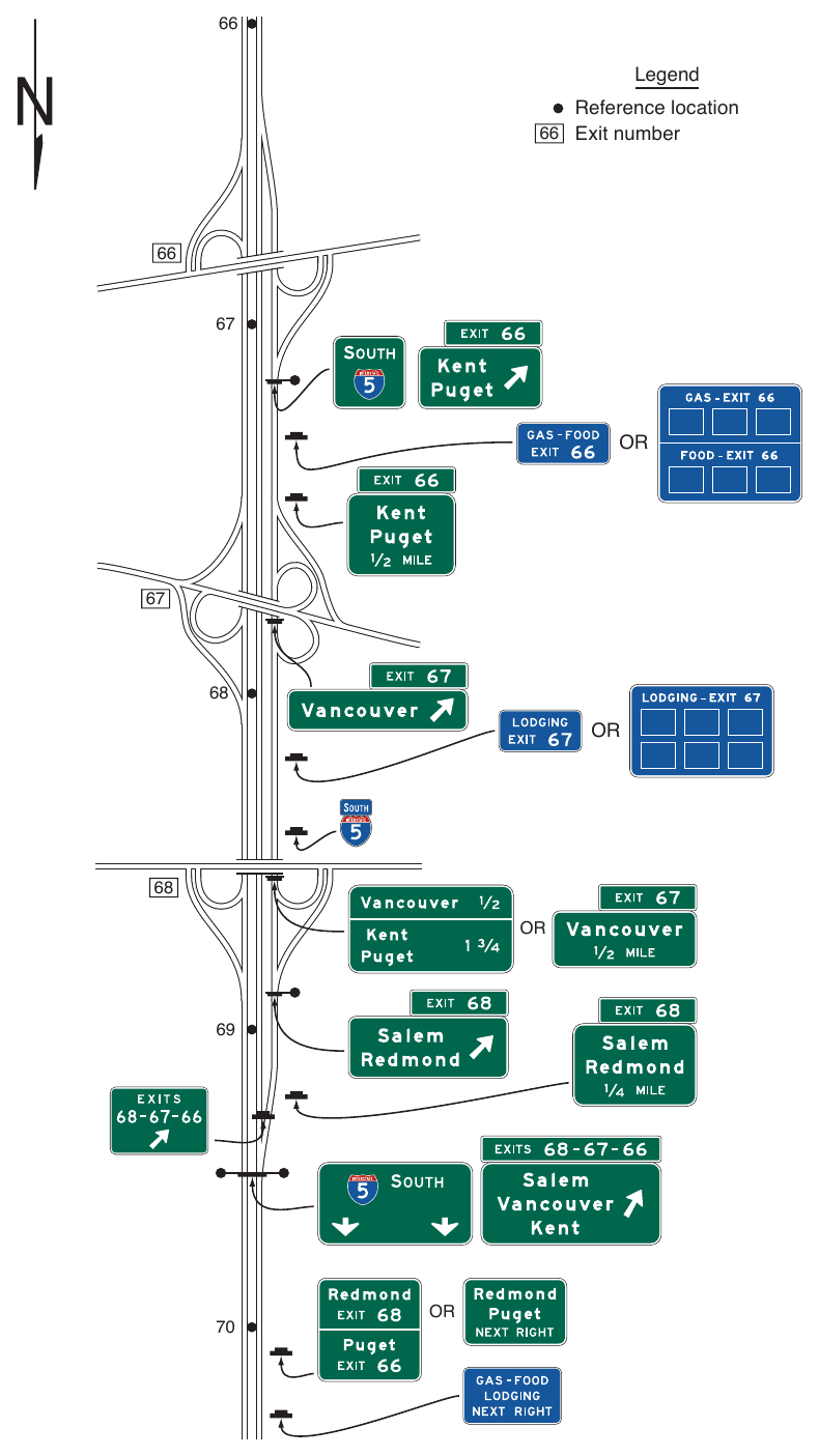
with Collector-Distributor Roadways (Sheet 2 of 2)
66. Legend Reference location 66 Exit number
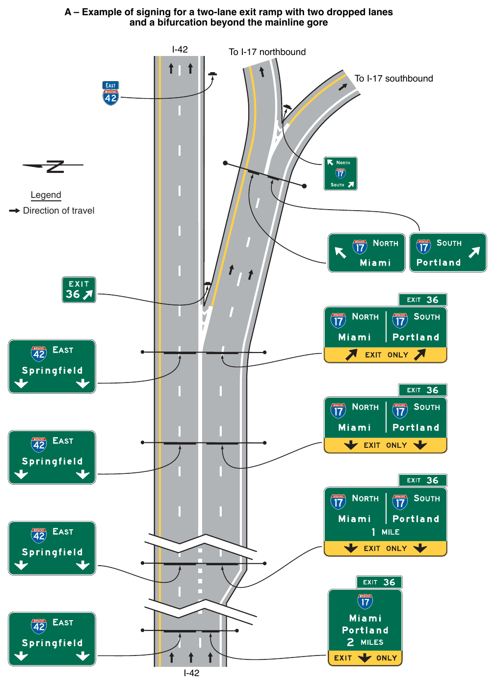
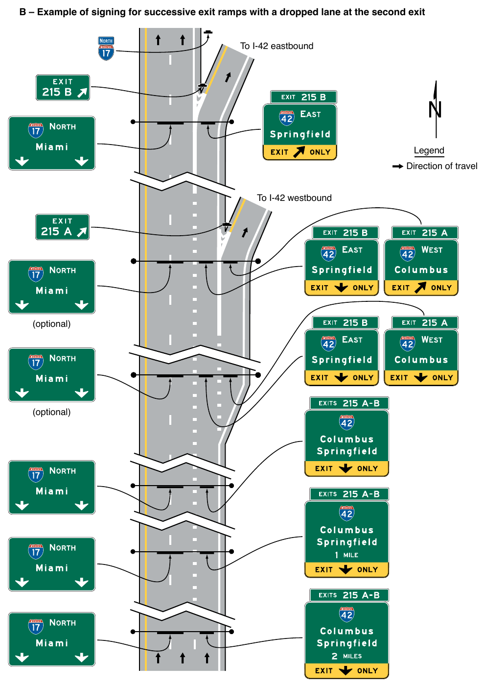
Support
An off-route movement is the movement that does not follow the through route. Drivers might not expect the off-route movement to be to the left or an optional lane at a split (see Figures 2E-38 and 2E-39). Section 2E.22 contains information about the use of the Left Exit Number (E1-5fP through E1-5kP) plaque at splits where the off-route movement is to the left. Sections 2E.39 and 2E.40 contain information about the use of Overhead Arrowper-Lane guide signs for freeway splits with an option lane and for multi-lane freeway-to-freeway exits having an option lane. Section 2E.41 contains information about the use of a Diagrammatic Advance guide sign for complex geometric configurations at ramp departures.
Standard
04. The roadway for the off-route shall be signed as an exit. If exit numbering is used, the signs shall comply with the provisions of Section 2E.22. Distance messages on the Advance guide signs shall comply with the provisions of Section 2E.23.
05. Overhead signs shall be used at a distance of 1 mile and at the theoretical gore of each connecting ramp. When Overhead Arrow-per-Lane or Diagrammatic Advance guide signs are used, they shall be located in accordance with the provisions of Sections 2E.40 and 2E.41, respectively.
Option
06. The Advance guide signs at the ½-mile and 2-mile locations may also be mounted overhead.
Guidance
07. An Advisory Exit Speed (W13-2) sign should be used where an engineering study shows that it is necessary to display a speed reduction message for ramp signing (see Section 2C.12).
§2E.38 Freeway Split with Dedicated Lanes¶
Standard
01. Signing for freeway splits with dedicated lanes shall use the sign designs shown in Figure 2E-34.
02. The arrows on each Interchange Advance guide sign shall match the number of lanes present at the location of the Advance guide sign.
03. The signs for this application shall be mounted overhead. When arrows are used, each arrow shall be located over the approximate center of the lane to which it applies.
04. Where one roadway of the split carries the through route, the other roadway of the split shall be signed as an exit. If exit numbering is used, the signs shall comply with the provisions of Section 2E.22. Distance messages on the Advance guide signs shall comply with the provisions of Section 2E.23.
05. The number and location of Advance guide signs shall comply with the provisions of Section 2E.23.
Guidance
06. The Exit Direction and Pull-Through signs should be located at the theoretical gore.
07. The Exit Direction and Pull-Through signs should display down arrows if the alignment is straight or diagonal upward-pointing directional arrows if the alignment is curved (see Section 2D.08).
Standard
08. The Exit Direction sign shall contain the EXIT ONLY (E11-1 series) sign panel (see Section 2E.28).
§2E.39 Signing for Option Lanes at Splits and Multi-Lane Exits¶
Support
01. Some freeway and expressway splits or multi-lane exit interchanges contain an interior option lane serving both movements in which traffic can either leave the route or remain on the route, or choose either destination at a split, from the same lane.
Standard
02. On freeways and expressways, Overhead Arrow-per-Lane guide sign designs, as provided in Section 2E.40, shall be used for all multi-lane exits at major interchanges (see Section 2E.11) that have an optional exit lane that also carries the through route (see Figures 2E-36, 2E-37, and 2E-42) and for all splits that include an option lane (see Figure 2E-38). Overhead Arrow-per-Lane guide signs shall not be used on freeways and expressways for any other types of exits or splits, including single-lane exits and splits that do not have an option lane.
Guidance
03. The Overhead Arrow-per-Lane guide sign design (see Section 2E.40) should also be considered for multilane exits with an option lane at intermediate interchanges (see Section 2E.11) based on such factors as the extent of the need to optimize the mainline operation by maximizing the usage of the option lane, the extent of the period(s) of the day during which the exiting volumes warrant the multi-lane exit arrangement, and the nature of the traffic that primarily uses the option lane during the high-volume periods.
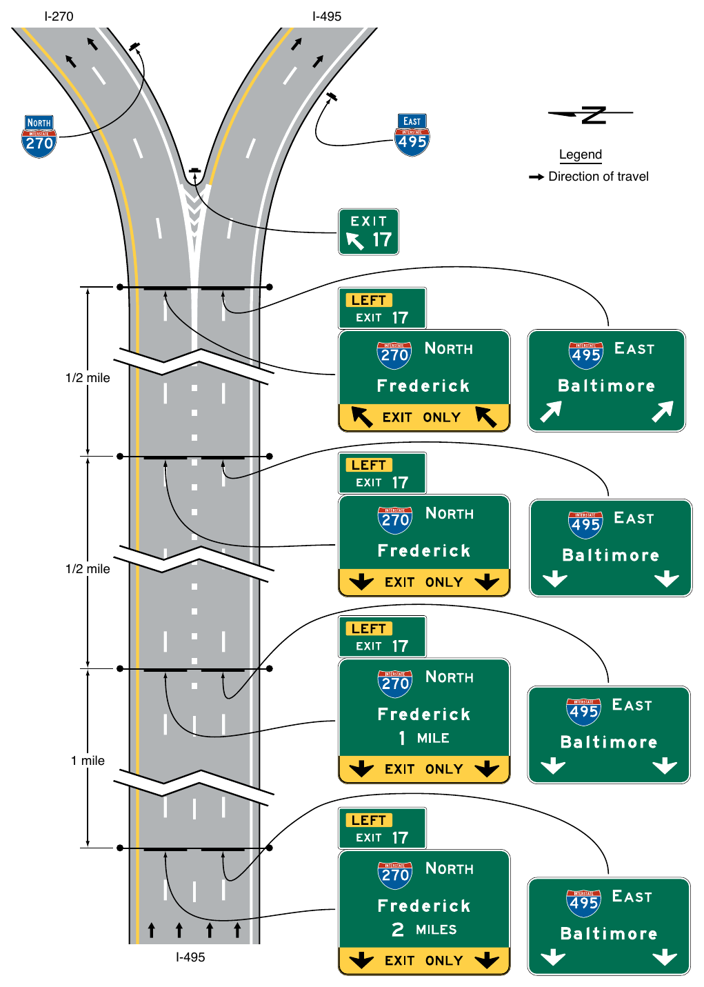
04. Signing at intermediate interchanges (see Section 2E.11) that have an optional exit lane at which it has been determined that the Overhead Arrow-per-Lane guide sign design is not warranted or at multi-lane exits at minor interchanges (see Section 2E.11) that have an optional exit lane should use signing in accordance with the provisions of Section 2E.42.
§2E.40 Design of Overhead Arrow-per-Lane Guide Signs for Option Lanes¶
Support
01. Overhead Arrow-per-Lane guide signs (see Figure 2E-35) are used where an option lane is present at freeway and expressway multi-lane exit interchanges and splits. They display an upward-pointing arrow above each lane that conveys the direction(s) of travel that the lane serves at the point of departure. At locations where an option lane is present at a multi-lane exit or split, Overhead Arrow-per-Lane guide signs have been shown to be superior to other guide sign designs because they convey positive direction about which destination and direction each approach lane serves, particularly for the option lane, which is otherwise difficult to clearly sign.
Standard
02. Overhead Arrow-per-Lane guide signs as provided in Section 2E.39 shall be used at all new or reconstructed freeway and expressway locations and at freeway and expressway locations where replacement of existing sign support structures is necessitated by reconstruction. The Overhead Arrow-per-Lane guide sign at the exit or split shall be located at or in the immediate vicinity of the point where the exiting lanes begin to diverge from the through lanes or, for a split, at the point where the approach lanes begin to diverge from one another, preserving the relation of the arrows displayed on the sign to their respective lanes. The Overhead Arrow-per-Lane guide sign at the exit shall not be located at or near the theoretical gore.
Option
03. At existing or non-reconstructed locations where an overhead Exit Direction sign exists at the theoretical gore, and the existing sign support structure is retained, an overhead Exit Direction sign may continue to be used on the existing sign support structure in conjunction with a replacement of the advance signs using the Overhead Arrowper-Lane guide sign design.
Standard
04. An Overhead Arrow-per-Lane guide sign shall not be used at the location of the Exit Direction sign at or in the vicinity of the theoretical gore when an Exit Direction sign is being retained as provided in Paragraph 3 of this Section. New installations of Exit Direction and Pull-Through signs shall not be permitted in conjunction with Overhead Arrow-per-Lane guide signs on new or reconstructed facilities.
Guidance
05. Overhead Arrow-per-Lane guide signs should be located at approximately ½ mile and 1 mile in advance of the exit or split, and at approximately 2 miles in advance of the exit or split where space is available and conditions allow.
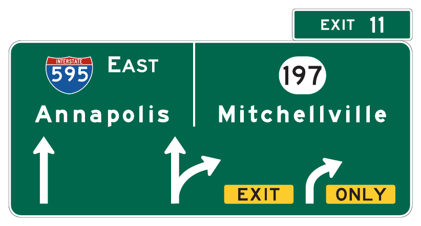
Standard
06. Overhead Arrow-per-Lane guide signs used on freeways and expressways shall be designed in accordance with the following criteria:
- A. Except as provided in Section 2E.42 for partial-width Overhead Arrow-per-Lane signs, the sign shall include an upward-pointing (vertical, curved, or bifurcated) arrow for each lane of the approach to the split or exit.
- B. The shaft of each arrow shall be located over the approximate center of the lane to which it applies.
- C. Arrows for continuing through lanes shall be vertically upward-pointing (see Figure 2E-36) unless the continuing through lanes are on a significantly curved alignment beyond the theoretical gore (see Figure 2E-37).
- D. The arrow for a lane that must exit shall be curved in the direction of the exit and shall be accompanied by black-on-yellow EXIT (E11-1a) and ONLY (E11-1b) sign panels adjacent to the lower end of the arrow shaft. The E11-1a and E11-1b sign panels shall not be used for a split of two overlapping routes where neither of the diverging routes is designated as an exit. Where the through lanes curve and the exit continues on a straight alignment, upward-pointing vertical arrows shall be used for the exiting movement and curved arrows for the through movement (see Figure 2E-37).
- E. The arrow for an optional exit lane that also carries the through route shall have a single shaft that bifurcates into a vertically upward-pointing arrow and a curving arrow corresponding to the configuration of the through and exit lanes.
- F. For splits with an option lane, the arrow for the lane from which either direction of the split can be accessed shall have a single shaft that bifurcates into two upward-pointing curving arrows (see Figure 2E-38).
- G. A vertical white line shall be used to separate the route shields and destinations for the two diverging movements from each other.
- H. The distance to the exit or split shall be displayed below the off-movement destination on the advance signs at the 1-mile and 2-mile locations.
- I. The number of lanes displayed on a sign shall correspond to the number of lanes at the location of that sign. An advance sign shall not depict lanes that are added downstream of the sign location.
- J. For numbered exits, the Exit Number (E1-5P through E1-5eP) or Left Exit Number (E1-5fP through E1-5kP) plaque shall be used at the top of the sign in accordance with Section 2E.23. For unnumbered exits to the left, a LEFT (E1-5mP) plaque shall be added on the top left-hand edge of and adjacent to the sign.
Guidance
07. Overhead Arrow-per-Lane guide signs used on freeways and expressways should be designed in accordance with the following additional criteria:
- A. No more than one destination should be displayed for each movement, and no more than two destinations should be displayed per sign.
- B. The arrowhead(s) for the diverging movement should be positioned lower on the sign than the arrowhead(s) for the movement that continues straight ahead, independent of which movement carries the through route. Where the movements are freeway or expressway splits rather than exits, the arrowheads should be positioned at approximately the same height on the sign.
- C. Route shields, cardinal directions, and destinations should be positioned on the sign such that they are clearly related to the arrowhead(s) for the movement to which they apply.
- D. The cardinal direction should be placed adjacent to the route shield for exits or splits leading in a single cardinal direction.
- E. The vertical white line that is used to separate the route shields and destinations for the two diverging movements from each other should not descend below the top of the arrowheads for the through lanes, and should be positioned approximately halfway between the diverging arrowheads for the optional movement lane (see Figure 2E-35).
Standard
08. Overhead Arrow-per-Lane guide signs shall not be used to depict a downstream split of an exit ramp on a sign located on the mainline.
Support
09. Specific guidelines for more detailed design of Overhead Arrow-per-Lane guide signs are contained in the “Standard Highway Signs” publication (see Section 1A.05).
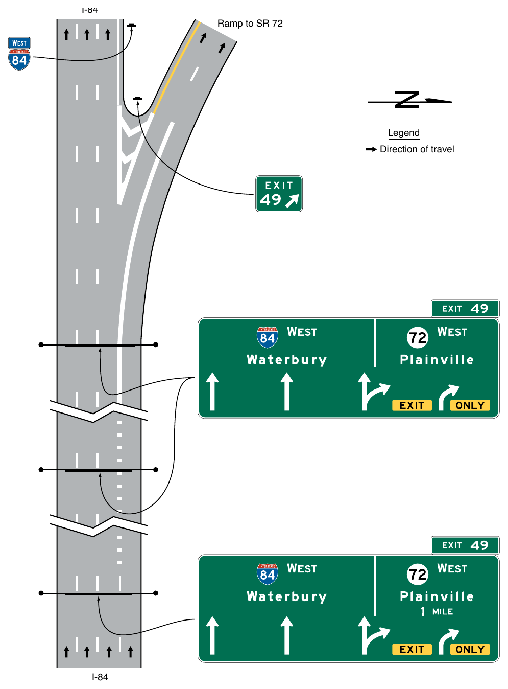
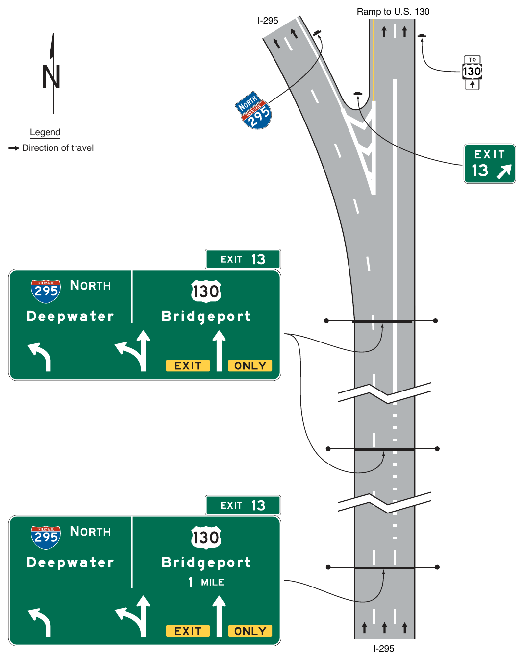
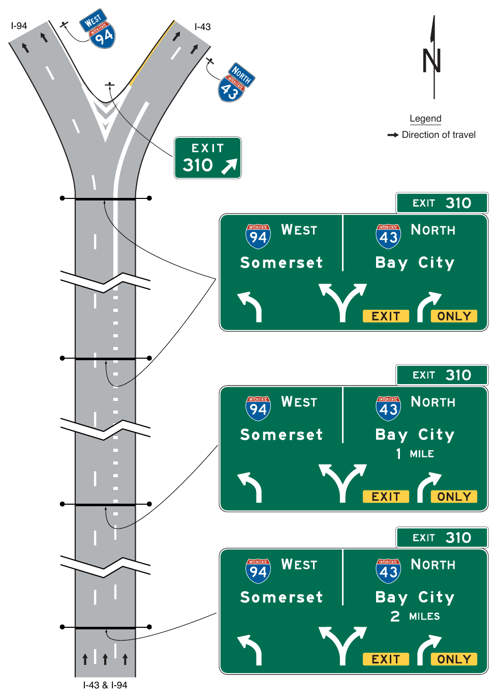
Standard
The arrow heights for Overhead Arrow-per-Lane guide signs on freeways and expressways shall be as shown in Table 2E-6.
Table 2E-6. Overhead Arrow-per-Lane Arrow Height Based on Principal Legend Letter Height
| Principal Legend Letter Height | Through Arrow | Turn Arrow | Through with Turn Arrow | Split Arrow |
|---|---|---|---|---|
| 20 | 48 | 38 | 48 | 42 |
| 16 or less | 39 | 30.875 | 39 | 34.125 |
Note: Letter and arrow heights are shown in inches.
Note: Letter and arrow heights are shown in inches.
Option
Where extra emphasis of an especially low advisory ramp speed is needed, an EXIT XX MPH (E13-2) sign panel (see Figure 2E-14) may be placed below the applicable destination legend to supplement, but not to replace, the exit or ramp advisory speed warning signs.
12. Warning Beacons in compliance with the provisions of Section 2E.25 may be used with the E13-2 sign panel.
Support
13. An example of guide signing for a narrow gore at a split with an option lane is shown in Figure 2E-39, and an example of guide signing for a narrow gore at a two-lane exit with an option lane is shown in Figure 2E-40.
Option
14. Where there is 800 feet or more between the beginning of the lane diverge and the theoretical gore, Exit Direction, and Pull-Through signs indicating the destinations allowed by each lane may be added in the vicinity of the theoretical gore to reinforce positive guidance (see Figures 2E-39 and 2E-40).
§2E.41 Design of Freeway and Expressway Diagrammatic Advance Guide Signs¶
Support
01. The Diagrammatic Advance guide sign (see Figure 2E-41) is a guide sign that shows a simplified graphic view of the exit departure arrangement in relationship to the main highway at an interchange. Its purpose is to provide advance notice of complex or unexpected road geometry or ramp departures at an interchange and/or depict successive decision points where additional context might be helpful to interpreting the subsequent primary Interchange Advance guide signs. Unlike Diagrammatic signs that were included in previous editions of this Manual, the Diagrammatic Advance guide sign does not depict which or the number of specific lanes that serve a particular destination or depict lanes added or reduced.
Option
02. A Diagrammatic Advance guide sign may be used in advance of the interchange guide sign sequence, or in lieu of an Interchange Advance guide sign located 2 miles in advance of the exit, to supplement conventional or Overhead Arrow-per-Lane guide signs used for a downstream interchange.
Standard
03. Diagrammatic Advance guide signs shall be designed in accordance with the following criteria:
- A. The graphic legend shall be of a plan view showing a simplified schematic graphic of the relative through and off-ramp movements.
- B. No symbols or route shields shall be used as a substitute for arrowheads.
- C. They shall not be installed at the Exit Direction sign location (see Section 2E.25).
- D. The EXIT ONLY sign panel shall not be used on Diagrammatic Advance guide signs in advance of the interchange.
- E. For numbered exits, the Exit Number (E1-5P through E1-5eP) or Left Exit Number (E1-5fP through E1-5kP) plaque shall be used at the top of the sign in accordance with Section 2E.22. For unnumbered left exits, the LEFT (E1-5mP) plaque shall be used at the top left edge of the sign.
- F. The graphic shall not depict deceleration or auxiliary lanes.
- G. Arrow shafts shall not contain lane lines.
- H. Destination legends for off-movements shall be positioned to the side of the arrow from which the ramp departs.
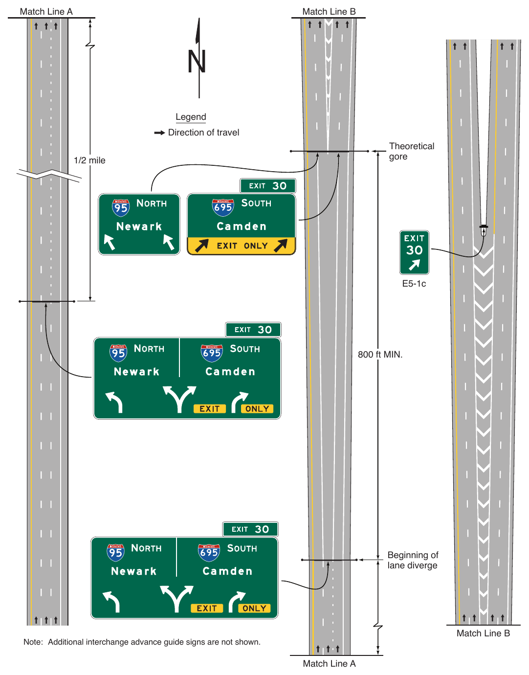
Signs shown: E5-1c
800 ft MIN. Beginning of lane diverge Match Line B Note: Additional interchange advance guide signs are not shown. Match Line A
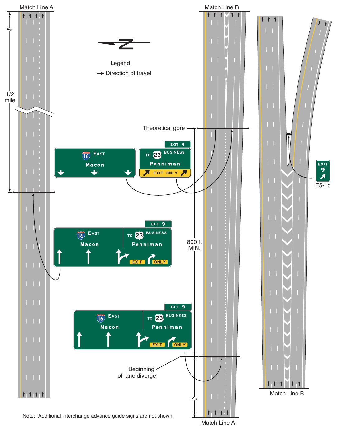
Signs shown: E5-1c
Note: Additional interchange advance guide signs are not shown. Match Line A
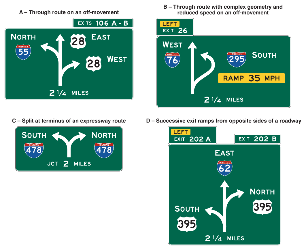
Guidance
Diagrammatic Advance guide signs used on freeways and expressways should be designed in accordance with the following additional criteria:
- A. No more than one destination should be displayed for each movement.
- B. The arrowhead for the diverging movement should be positioned lower on the sign than the arrowhead for the movement that continues straight ahead, independent of which movement carries the through route (see Figure 2E-42). Where the movements are freeway or expressway splits rather than exits, the arrowheads should be positioned at approximately the same height on the sign.
- C. Arrow shaft widths should not vary for different movements.
- D. Route shields, cardinal directions, and destinations should be positioned on the sign such that they are clearly related to the arrowhead(s), and the arrowhead for the off movement should point toward the route shield or, for unnumbered routes, the upper line of destination legend for the off movement.
- E. For exits or splits leading in a single direction, the cardinal direction should be placed adjacent to the route shield, and the destination should be placed below the route shield and cardinal direction.
- F. Where two exits are displayed on a Diagrammatic Advance guide sign, the control destination for the through route should be omitted from the sign.
- G. The distance legend should be placed below the exit destination legend. For splits where neither direction carries a through route, the distance legend should be centered below the diagrammatic arrow. Where successive exits from the same side of the roadway are displayed, the distance legend should be placed below the destination legend for the first exit, with the distance to the second exit omitted. Where successive exits from opposite sides of the roadway are displayed, the distance to the first exit should be centered below the diagrammatic arrow, with the distance to the second exit omitted.
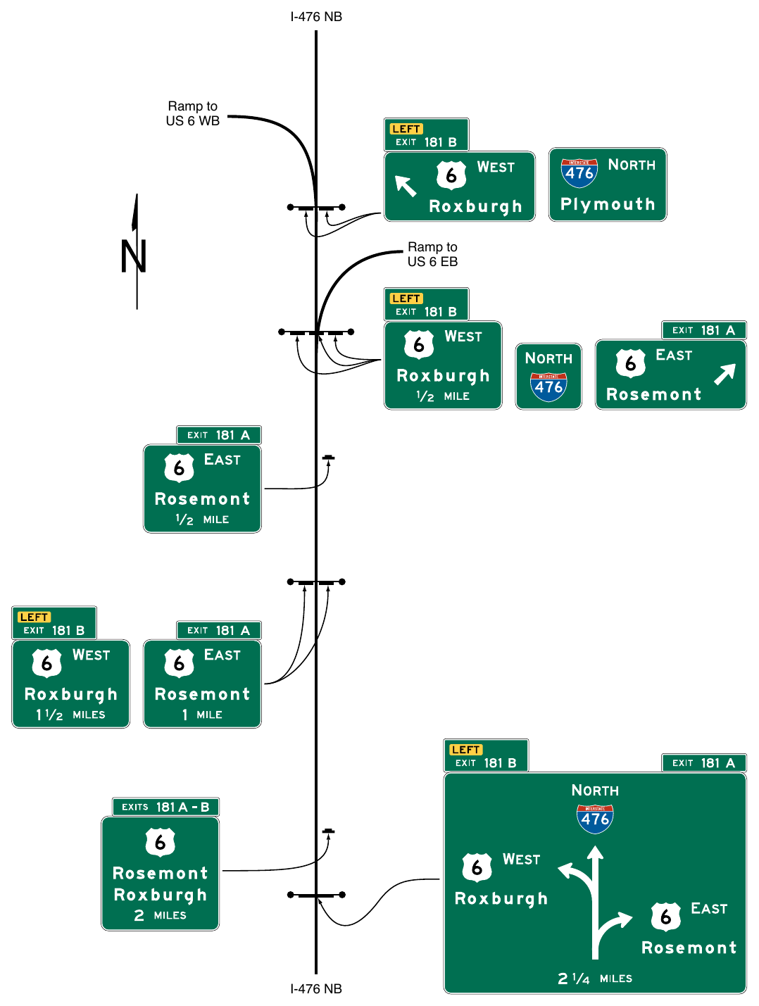
Standard
Diagrammatic Advance guide signs shall not be used at cloverleaf interchanges for the purpose of depicting separate downstream departures from a collector-distributor roadway.
06. Diagrammatic Advance guide signs located on the main roadway shall not be used to depict a downstream split of an exit ramp.
Support
07. Specific guidelines for more detailed design of Diagrammatic Advance guide signs are contained in the “Standard Highway Signs” publication (see Section 1A.05).
Option
08. Where extra emphasis of an especially low advisory ramp speed is needed, an EXIT XX MPH (E13-2) sign panel (see Figure 2E-14) may be placed below the applicable destination legend to supplement, but not to replace, the exit or ramp advisory speed warning signs.
09. Warning Beacons in compliance with the provisions of Section 2E.25 may be used with the E13-2 sign panel.
10. Diagrammatic Advance guide signs may be used on any class of roadway and may be modified to depict relative movements for intersections on conventional roads.
§2E.42 Signing for Intermediate and Minor Interchange Multi-Lane Exits with an Option Lane¶
Support
01. Intermediate and minor multi-lane exits might have an operational need for the presence of an option lane for only the peak period during which excessive queues might otherwise develop if the option lane were not available. In such cases, the Overhead Arrow-per-Lane guide signing described for option lanes in Sections 2E.39 and 2E.40 might not be practical, depending on the level of use of the option lane and the spacing of nearby interchanges, particularly in non-rural areas.
Guidance
02. When full-width Overhead Arrow-per-Lane guide signing is not practical, as described in Paragraph 1 of this Section, signing for an intermediate or minor interchange that has a multi-lane exit with an option lane that also carries the through route should use a partial-width form of the Overhead Arrow-per-Lane guide sign (see Figures 2E-43 through 2E-45). The partial-width Overhead Arrow-per-Lane sign should display arrows only for the option lane and the mandatory exit lane(s) using the same bifurcated arrow type for the option lane and curved arrow type for the exit only lane(s) as are used for the full-width Overhead Arrow-per-Lane sign. The legend displayed for the exit movement should be clearly aligned with the arrows pointing in the direction of the exit and not with the vertical arrowhead of the bifurcated arrow depicting the through movement.
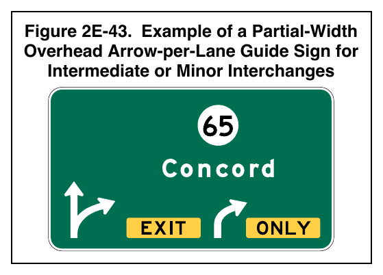
Standard
03. The through route and/or destination shall not be displayed on the partial-width Overhead Arrow-per-Lane guide sign.
04. Partial-width Overhead Arrow-per-Lane signs shall be located in compliance with the provisions of Section 2E.40 for full-width Overhead Arrow-per-Lane signs (see Figures 2E-44 and 2E-45).
Option
05. At an intermediate or minor interchange that has a multi-lane exit with an option lane that also carries the through route, where full-width Overhead Arrow-per-Lane guide signing is not practical, conventional signing as provided in Paragraphs 7 through 9 of this Section may be used (see Figures 2E-46 and 2E-47).
06. When partial-width Overhead Arrow-per-Lane signing is used at existing or non-reconstructed locations where an overhead Exit Direction sign exists at the theoretical gore, and the existing sign support structure is retained, an overhead Exit Direction sign may continue to be used on the existing sign support structure in conjunction with a replacement of the advance signs using the partial-width Overhead Arrow-per-Lane guide sign design (see Figure 2E-44).
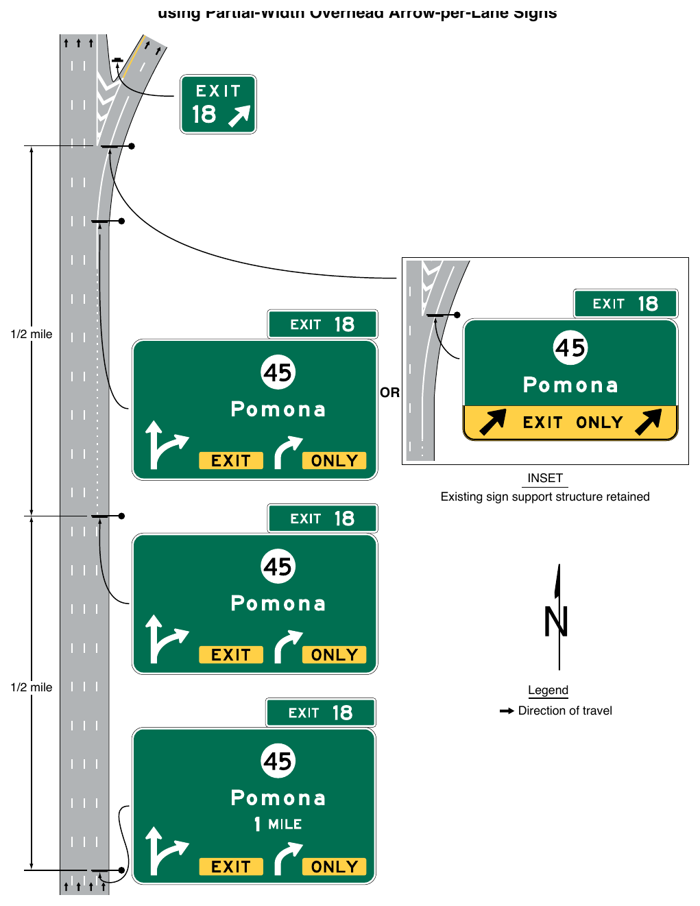
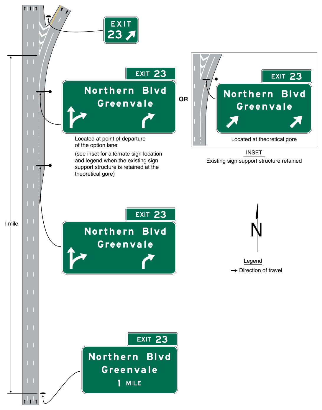
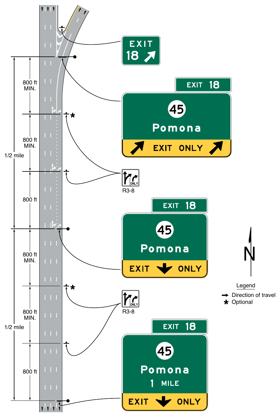
Signs shown: R3-8
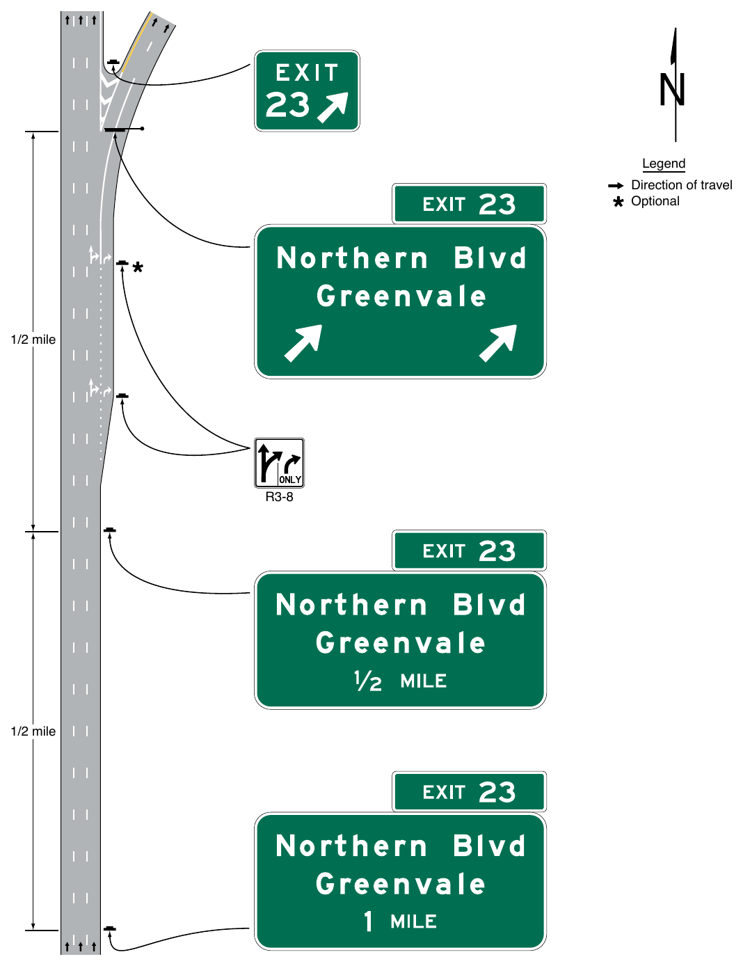
Signs shown: R3-8
Guidance
07. When conventional signing is used, the option lane should not be signed on the Interchange Advance guide signs. For such exits that involve the addition of an auxiliary lane that is not present at the Interchange Advance guide sign locations, but do not involve a lane drop (see Figure 2E-47), a sequence of post-mounted or overhead-mounted Interchange Advance guide signs should be used, located in accordance with the interchange classification (see Section 2E.11). The Exit Direction sign should be located at the theoretical gore and should display a diagonally upward-pointing directional arrow above each lane that departs from the mainline alignment. The Exit Direction sign should not contain the EXIT ONLY legend.
08. For such interchanges that also have a lane drop (see Figure 2E-46), the Interchange Advance guide and Exit Direction signs should follow the provisions of Section 2E.28. The Exit Direction sign should be located at the theoretical gore and should contain the EXIT ONLY (E11-1e) sign panel.
09. Where partial-width Overhead Arrow-per-Lane guide signs are not used, the presence of the option lane should be conveyed by the use of post-mounted lane-use (R3-8 series) signs (see Section 2B.30). When used, the R3-8 signs should be of an appropriate size for their application to optimize their conspicuity. The signs should be located in succession with the Interchange Advance guide signs, where the option and exit lanes have developed (see Figure 2E-46). In cases where the exiting lane or lanes have not developed and the option lane is created by the addition of an auxiliary lane that exits, the R3-8 signs should be located only adjacent to where the lanes have been fully developed and not in advance of the lane or along its transition (see Figure 2E-47).
Support
10. The use of a down arrow on overhead freeway or expressway guide signs has been shown to be misinterpreted by road users as an indication of a dedicated lane.
Standard
11. Interchange Advance guide signs that are mounted overhead shall not display a down arrow over an option lane.
§2E.43 Number of Signs at an Overhead Installation and Sign Spreading¶
Guidance
01. If overhead signs are warranted, as set forth in Section 2A.14, the number of signs at these locations should be limited to only those essential in communicating pertinent destination information to the road user. Exit Direction signs for a single exit and the Interchange Advance Guide signs should have only one sign with one or two destinations. Regulatory signs, such as speed limits, should not be used in conjunction with overhead guide sign installations. Because road users have limited time to read and comprehend sign messages, there should not be more than three guide signs displayed at any one location either on the overhead structure or its support.
Option
02. At overhead locations, more than one sign may be installed to advise of a multiple exit condition at an interchange. If the roadway ramp or crossroad has complex or unusual geometrics, additional signs with confirming messages may be provided to properly guide the road user.
Support
03. Sign spreading is a concept where major overhead signs are spaced so that road users are not overloaded with a group of signs at a single location. Figure 2E-48 illustrates an example of sign spreading.
Guidance
04. Where overhead signing is used, sign spreading should be used at all single-exit interchanges and to the extent possible at multi-exit interchanges. Sign spreading should be accomplished by use of the following:
- A. The Exit Direction sign should be the only guide sign used in the vicinity of the gore (other than the Exit Gore sign). It should be located overhead near the theoretical gore and generally on an overhead sign support structure.
- B. The Interchange Advance guide sign to indicate the next interchange exit should be placed near the crossroad location. If the crossroad goes over the mainline, the Interchange Advance guide sign should be placed on the overcrossing structure or on a separate structure immediately in front of the overcrossing structure.
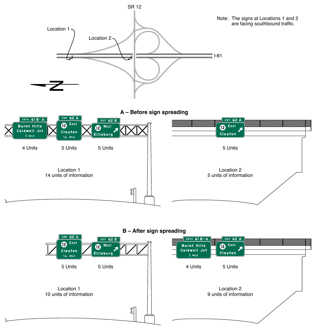
Note: The signs at Locations 1 and 2 are facing southbound traffic. Location 1 Location 2 A – Before sign spreading 4 Units 5 Units 5 Units 5 Units Location 1 14 units of information Location 2 5 units of information B – After sign spreading 5 Units Location 1 10 units of information 5 Units 4 Units 5 Units Location 2 9 units of information
§2E.44 Closely-Spaced Interchanges¶
Support
01. Section 2E.43 contains information regarding sign spreading where the Exit Direction sign and the Interchange Advance guide sign for the next interchange are mounted overhead. Sign spreading is particularly beneficial where interchanges are closely spaced and overhead signing is used in conjunction with Interchange Sequence signs as provided in Paragraph 2 of this Section.
Guidance
02. Interchange Sequence signs (see Section 2E.24) should be used at closely-spaced interchanges. When used, they should identify and show street names and distances for the next two or three exits as shown in Figure 2E-11.
Standard
03. Interchange Advance guide signs for closely-spaced interchanges shall show information for only one interchange.
§2E.45 Guide Signing in Tunnels and Similar Structures¶
Support
01. The application of the provisions for freeway and expressway guide signs in tunnels and other similar structures can present unique challenges not encountered elsewhere due to the extended and continuous distances of constrained vertical and horizontal clearances in which to place signs. The effect of these constraints is particularly evident when there are interchange exit ramps inside the tunnel that require guide signing. As a result, it might not always be possible to use the typical layouts for guide signs inside a tunnel. In addition, interchange guide signs might need to be limited to one destination only, with other destinations displayed separately on Supplemental guide signs (see Section 2E.51). Acceptable methods to modify the layout of a sign to fit the space available in a tunnel are provided in Paragraph 2 of this Section.
Option
02. Overhead-mounted guide signs in tunnels, or in other similar structures with extended constrained vertical and horizontal clearances, may be modified in accordance with the following when needed to accommodate limited vertical clearance available for signs:
- A. Some sign legend elements may be arranged side by side, such as by placing route shields to the left of the destination instead of above.
- B. The Exit Number plaque (see Section 2E.22) may be placed at the right-hand edge of the sign for right exits or at the left-hand edge of the sign for left exits instead of at the top edge of the sign. The legend of the Exit Number plaque may use a reduced letter height of not less than 6 inches for the word EXIT(S) and not less than 12 inches for numerals and suffixes.
- C. Destination and roadway names may be displayed in reduced letter heights with an initial upper-case letter of not less than 10.67 inches, when determined acceptable based on consideration of reduced speed and other relevant factors, while maintaining adequate space between the legend and edges of the sign to ensure legibility and quick recognition.
- D. Unusually long destination and roadway names that cannot be adequately shortened or otherwise acceptably abbreviated may be displayed using Series D letters in lieu of Series E(modified).
Standard
03. Applicability of the provisions of Paragraph 2 of this Section shall be limited to those signs within the limits of the tunnel or other similar structure and shall not be extended to the approaches to or departures from the tunnel.
Support
04. Unlike typical guide signs that are exposed to rain, guide signs in tunnels accumulate grime and residue quickly. This accumulation can reduce visual contrast between legend and background and reduce the retroreflectivity of the sign sheeting. Therefore, guide signs in tunnels generally need more maintenance.
Guidance
05. Overhead signs in tunnels should have external or internal sign illumination to ensure adequate visibility between scheduled maintenance and cleanings.
06. One or more Interchange Sequence signs (see Section 2E.24) should be used on the approach to the tunnel entrance to display the distances to the next interchanges that have exit ramps inside the tunnel or immediately following the end of the tunnel.
07. Supplementary pavement markings, such as word, arrow, and/or route shield markings, should be considered inside the tunnel in addition to the basic lane and edge line markings.
OTHER GUIDE SIGNS¶
§2E.46 Next Exit Plaques (E2-1P and E2-1aP)¶
Option
01. Where the distance to the next interchange is unusually long, a Next Exit (E2-1P or E2-1aP) plaque (see Figure 2E-49) may be installed to inform road users of the distance to the next interchange.

Guidance
02. The Next Exit plaque should not be used unless the distance between successive interchanges is more than 5 miles.
03. Where the Next Exit plaque is used, the E2-1P plaque should be used where the width of the Interchange Advance guide sign is equal to or greater than the width of the E2-1P plaque. The E2-1aP plaque should be used where the width of the E2-1P plaque exceeds the width of the Interchange Advance guide sign.
Standard
04. The Next Exit plaque shall display the legend NEXT EXIT XX MILES. If the Next Exit plaque is used, it shall be placed below the Interchange Advance guide sign nearest the interchange. It shall be mounted so as to not adversely affect the breakaway feature of the sign support structure.
§2E.47 Post-Interchange Signs¶
Guidance
01. If space between interchanges permits, as in rural areas, and where undue repetition of messages will not occur, a fixed sequence of signs should be displayed beginning 500 feet beyond the downstream end of the acceleration lane. At this point a Route Sign assembly should be installed followed by a Speed Limit sign and a Distance sign, each at a spacing of 1,000 feet (see Figure 2E-2).
02. If space between interchanges does not permit placement of these three post-interchange signs without encroaching on or overlapping the Advance guide signs necessary for the next interchange, or in rural areas where the interchanging traffic is primarily local, one or more of the post-interchange signs should be omitted.
Option
03. Usually the Distance sign will be of less importance than the other two signs and may be omitted, especially if Interchange Sequence signs are used. If the sign for through traffic on an overhead assembly already contains the route sign, the post-interchange route sign assembly may also be omitted.
§2E.48 Post-Interchange Distance Signs (E7-1 through E7-3)¶
Standard
01. If used, the Post-Interchange Distance sign (see Figure 2E-50) shall consist of a one-line, two-line, or three-line sign displaying the names of significant destination points and the distances to those points. The top line of the sign shall identify the next meaningful interchange with the name of the community near or through which the route passes, or if there is no community, the route number or name of the intersected highway.
Support
02. The minimum sizes of the route shields identifying a significant destination point are prescribed in Tables 2E-3 and 2E-5.
Option
03. The text identification of a route may be displayed instead of a route shield, such as “U S XX,” “[State abbreviation] XX” (such as “Del XX”), or “County XX.”
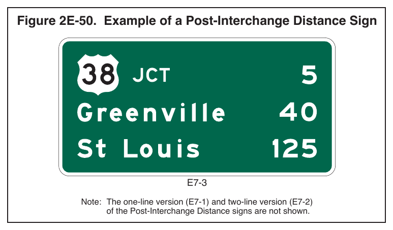
Guidance
04. If a second line is used, it should be reserved for communities of general interest that are located on or immediately adjacent to the route or for major traffic generators along the route.
Option
05. The choice of names for the second line, if it is used, may be varied on successive Distance signs to give road users maximum information concerning communities served by the route.
Standard
06. The third, or bottom line, shall contain the name and distance to a control city (if any) that has national significance for travelers using the route.
Guidance
07. Distances to the same destinations should not be shown more frequently than at 5-mile intervals. The distances displayed on these signs should be the actual distance to the destination points and not to the exit from the freeway or expressway. The distance displayed for each community should comply with the provisions of Section 2D.43.
§2E.49 Post-Interchange Travel Time Sign (E7-4)¶
Support
01. At certain locations, it might be more meaningful to recurrent road users to display the travel time rather than the distance to a destination. Such instances might be areas of adverse roadway conditions due to weather, such as in mountain passes or high elevations, congestion that occurs during peak travel seasons, or recurring congestion.
02. Section 2E.50 contains information on Distance and Travel Time and Comparative Travel Time signs.
Standard
03. If used, the Post-Interchange Travel Time (E7-4) sign (see Figure 2E-51) shall replace the Post-Interchange Distance sign in the series of post-interchange signs (see Section 2E.47).
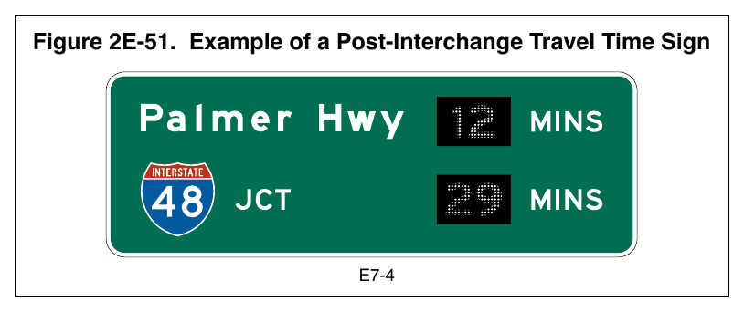
04. The Post-Interchange Travel Time sign shall comply with the provisions of Paragraph 1 of Section 2E.48 with the following exceptions:
- A. The distance shall be replaced with a changeable message element to display the current travel time to the applicable destination; and
- B. The abbreviation MINS shall follow the changeable message element.
05. Travel times shall not be used on Interchange guide signs (see Section 2E.21).
§2E.50 Distance and Travel Time Sign (E7-5) and Comparative Travel Time Sign (E7-6)¶
Support
01. Some locations might benefit from a travel time message displayed with the distance, or comparative travel times displayed for alternative routes to a common destination. These locations are often in advance of an urbanized area where interchanges become more closely spaced and/or in advance of a circumferential or other alternative route(s) where the road user can decide to divert depending on the destination. Nonetheless, these signs are typically located in advance of a decision point where the road user can divert to an alternate route to avoid recurring congestion.
02. Section 2E.49 contains information on Post-Interchange Travel Time signs.
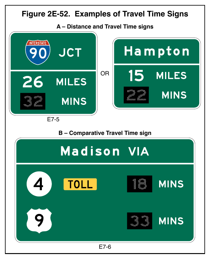
03. Section 2G.19 contains information on Comparative Travel Time signs for parallel lanes within the same highway route, such as for general-purpose lanes and managed lanes.
Standard
04. The Distance and Travel Time (E7-5) sign (see Figure 2E-52) shall display a major destination, landmark, or junction; a distance message; and a travel time message, each on a separate line. The distance units shall be displayed in the distance message. The travel time shall be displayed in a changeable message element and the abbreviation MINS shall follow the changeable message element. The Distance and Travel Time sign shall not display distance and time to more than one destination or junction.
05. The Comparative Travel Time (E7-6) sign (see Figure 2E-52) shall display a major destination, landmark, or junction, and two alternative routes with travel time messages. Each alternative route and associated travel time message shall be on a separate line. The travel time shall be displayed in a changeable message element and the abbreviation MINS shall follow the changeable message element.
06. Comparative travel times shall not be used to promote different modes of travel, such as personal vehicle highway travel compared with transit, or different forms of transit.
Guidance
07. Where used, the Distance and Travel Time sign should be located between interchanges and away from the sequence of interchange guide signs or other major signs.
08. Where used, the Comparative Travel Time sign should be located in advance of the sequence of interchange guide signs to provide adequate time for the road user to decide whether to reroute.
§2E.51 Supplemental Guide Signs (E3 Series)¶
Support
01. Supplemental guide signs (see Figure 2E-53) can be used to provide information regarding destinations accessible from an interchange, other than places displayed on the standard interchange signing. However, such Supplemental guide signing can reduce the effectiveness of other more important guide signing because of the possibility of overloading the road user’s capacity to receive visual messages and make appropriate decisions. The “AASHTO Guidelines for the Selection of Supplemental Guide Signs for Traffic Generators Adjacent to Freeways” is incorporated by reference in this Section.
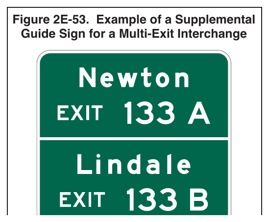
Guidance
02. Use of Supplemental guide signs should be limited to situations where there is a demonstrated need to sign for more destinations from an interchange than those that are displayed on the Interchange Advance guide and Exit Direction signs.
03. A Supplemental guide sign should not be installed unless a destination meets the criteria established by the State or agency policy. States and other agencies should adopt an appropriate policy for installing Supplemental guide signs using the “AASHTO Guidelines for the Selection of Supplemental Guide Signs for Traffic Generators Adjacent to Freeways.” In developing policies for such signing, such items as population, amount of traffic generated, distance from the route, and the significance of the destination, should be taken into account.
04. No more than one Supplemental guide sign should be used on each interchange approach.
05. A Supplemental guide sign should display no more than two destinations and no more than three lines of destination names. Destination names should be followed by the interchange exit number (and suffix), or if interchanges are not numbered, by the legend NEXT RIGHT or SECOND RIGHT or both, as appropriate. The Supplemental guide sign should be installed as an independent guide sign assembly.
06. Where two or more Interchange Advance guide signs are used, the Supplemental guide sign should be installed approximately midway between two of the Interchange Advance guide signs. If only one Interchange Advance guide sign is used, the Supplemental guide sign should follow it by at least 800 feet. If the interchanges are numbered, the interchange exit number should be used for the action message.
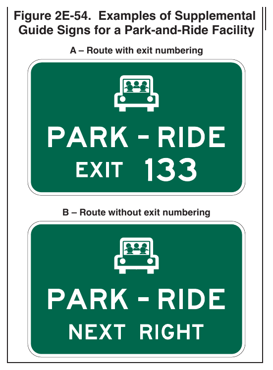
07. A Supplemental guide sign should not be installed in the same location with or where it will detract from guide signs for a different interchange.
Standard
08. No more than two supplemental traffic generator destinations shall be signed from a single interchange approach and four from a single interchange along the main roadway (see Paragraphs 4 and 5 of this Section regarding the number of Supplemental guide signs at an interchange and the number of destinations displayed on a Supplemental guide sign).
09. Supplemental guide signs shall not be placed at the same location as Interchange Advance guide, Exit Direction, or other signs related to an exit or interchange.
10. Guide signs for park-and-ride facilities shall be considered as Supplemental guide signs (see Figure 2E-54).
11. Guide signs for recreational or cultural interest destinations (see Chapter 2M) shall be considered as Supplemental guide signs, except where the interchange provides direct access to such a destination and the destination is instead displayed on the Interchange Advance guide and Exit Direction signs.
Option
12. The pictograph of a transit provider (see definition in Section 1C.02) may be displayed on the PARK – RIDE Supplemental guide sign or on a Supplemental guide sign for a transit facility.
Guidance
13. The use of a transit pictograph and/or the carpool symbol on the PARK – RIDE Supplemental guide sign should comply with the provisions of Paragraph 5 of Section 2D.48.
Standard
14. When a transit pictograph is displayed on the PARK – RIDE Supplemental guide sign, it shall be located on the same line as the carpool symbol, if used, above the word legend.
15. The maximum dimension (height or width) of a pictograph on a sign shall not exceed two times the upper-case letter height of the destination or PARK – RIDE legend.
§2E.52 Community Interchanges Identification Signs (E9-4 and E9-5)¶
Support
01. For suburban or rural communities served by two or three interchanges, Community Interchanges Identification (E9-4 and E9-5) signs (see Figure 2E-55) reduce the amount of information displayed on the Interchange Advance guide and Exit Direction signs by eliminating repetition of the same destinations for separate interchanges.
Guidance
02. In these cases, the name of the community followed by the word Exits should be displayed on the top line; the lines below should display the destination, road name or route number, and the corresponding distances to the nearest ¼ mile.
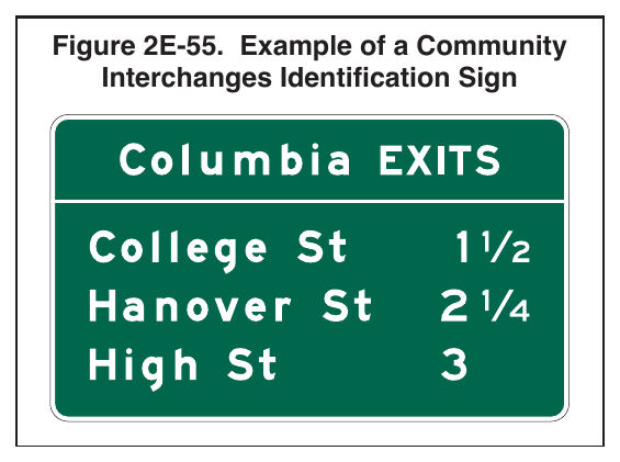
03. The sign should be located in advance of the first Interchange Advance guide sign for the first interchange within the community (see Figure 2E-56).
04. The legend displayed on the Interchange Advance guide and Exit Direction signs for each interchange should be consistent with the interchange names displayed on the Community Interchanges Identification sign. The name of the community displayed on the Community Interchanges Identification signs should be omitted from the legends of the Interchange Advance guide and Exit Direction signs.
Option
05. If interchanges are not conveniently identifiable or if there are more than three interchanges to be identified, the Next Exits sign (see Section 2E.53) may be used.
§2E.53 Next Exits Signs (E9-3 and E9-3a)¶
Support
01. Many freeways or expressways pass through historical or recreational regions, or urban areas served by a succession of several interchanges.
Option
02. Such regions or areas may be indicated by a Next Exits (E9-3 or E9-3a) sign (see Figure 2E-57) located in advance of the Advance guide sign or signs for the first interchange.
Guidance
03. The sign legend should identify the region or area followed by the words NEXT XX EXITS.
04. The legend displayed on the Interchange Advance guide and Exit Direction signs for each interchange should not display the region or area name that is displayed on the Next Exits sign (see Figure 2E-58).
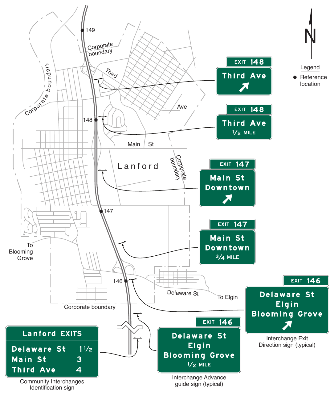
b o u n d ary ate Corpor y r a d n u bo Legend Th ird ra te Reference location Co rp o Ave
§2E.54 Weigh Station Signing¶
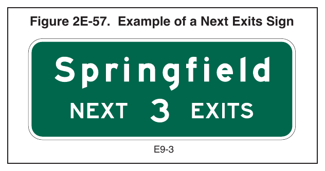
Signs shown: E9-3
Support
01. Independent facilities or areas have been added along many highways where certain commercial vehicles are directed to stop to be weighed or inspected. These areas are sometimes permanent, such as in a roadside area, or temporary mobile facilities deployed along the roadway.
02. The general concept for signing permanent Weigh Stations is similar to Rest Area signing (see Section 2I.05) because in both cases traffic using either area remains within the highway right-of-way.
Standard
03. The standard sequence of signs for a Weigh Station on an expressway or freeway shall include four basic signs (see Figure 2E-59):
- A. An Advance Weigh Station Distance (D8-1) sign with the distance 1 MILE displayed,
- B. An Advance Weigh Station Distance (D8-1) sign with the distance ½ MILE displayed, or a Weigh Station Advance Direction (D8-2) sign,
- C. A Weigh Station Entrance Direction (D8-3) sign, and
- D. A Weigh Station Gore sign (with the same legend as the Entrance Direction (D8-3) sign).
Option
04. When spacing of 1 mile and ½ mile are not practical for the D8-1 signs, the 1 MILE and ½ MILE distances on the D8-1 signs may be adjusted to match the spacing determined by engineering judgment.
05. Where State law requires trucks of a certain weight to enter the weigh station, a Weigh Station (R13-1) regulatory sign (see Section 2B.65) may be added to the sign sequence as shown in Figure 2E-59.
06. Where only commercial vehicle inspections are conducted in the inspection area and vehicles are not weighed, the WEIGH STATION legend of the D8 series signs may be replaced with the alternate legend, COMMERCIAL VEHICLE INSPECTION AREA.
Standard
07. When the WEIGH STATION legend of the D8 series signs is replaced with COMMERCIAL VEHICLE INSPECTION AREA legend as provided for in Paragraph 6 of this Section, the WEIGH STATION legend of the R13-1 sign shall be replaced with the alternate legend INSPECTION AREA.
08. A changeable legend display that displays either OPEN or CLOSED shall be included in the signing sequence to indicate when trucks are required to enter the weigh station.
Guidance
09. The required changeable legend described in Paragraph 8 of this Section should be displayed within and at the bottom of the Weigh Station Advance Direction (D8-2) sign or the Advance Weigh Station Distance (D8-1) sign, or on a supplemental plaque or sign panel.
Option
10. A plaque with the legend OPEN WHEN FLASHING may be added to one of the Advance Weigh Station Distance signs along with associated flashing beacons, in place of the changeable legend OPEN or CLOSED sign, to indicate when commercial vehicles are required to enter the weigh station.
Support
11. Weigh Station Area sign layouts for freeway and expressway applications are shown in the “Standard Highway Signs” publication (see Section 1A.05). An example of weigh station signing for use on freeways and expressways is shown in Figure 2E-59.
§2E.55 Route Signs and Trailblazer Assemblies¶
Guidance
01. Route signs (see Figure 2E-60) should be incorporated as cut-out shields or other distinctive shapes on large directional guide signs. Where the Interstate shield is displayed in an assembly or on the face of a guide sign with U.S. or State Route signs, the Interstate numeral should be at least equal in size to the numerals on the other Route signs. The use of independent Route signs should be limited primarily to route confirmation assemblies.
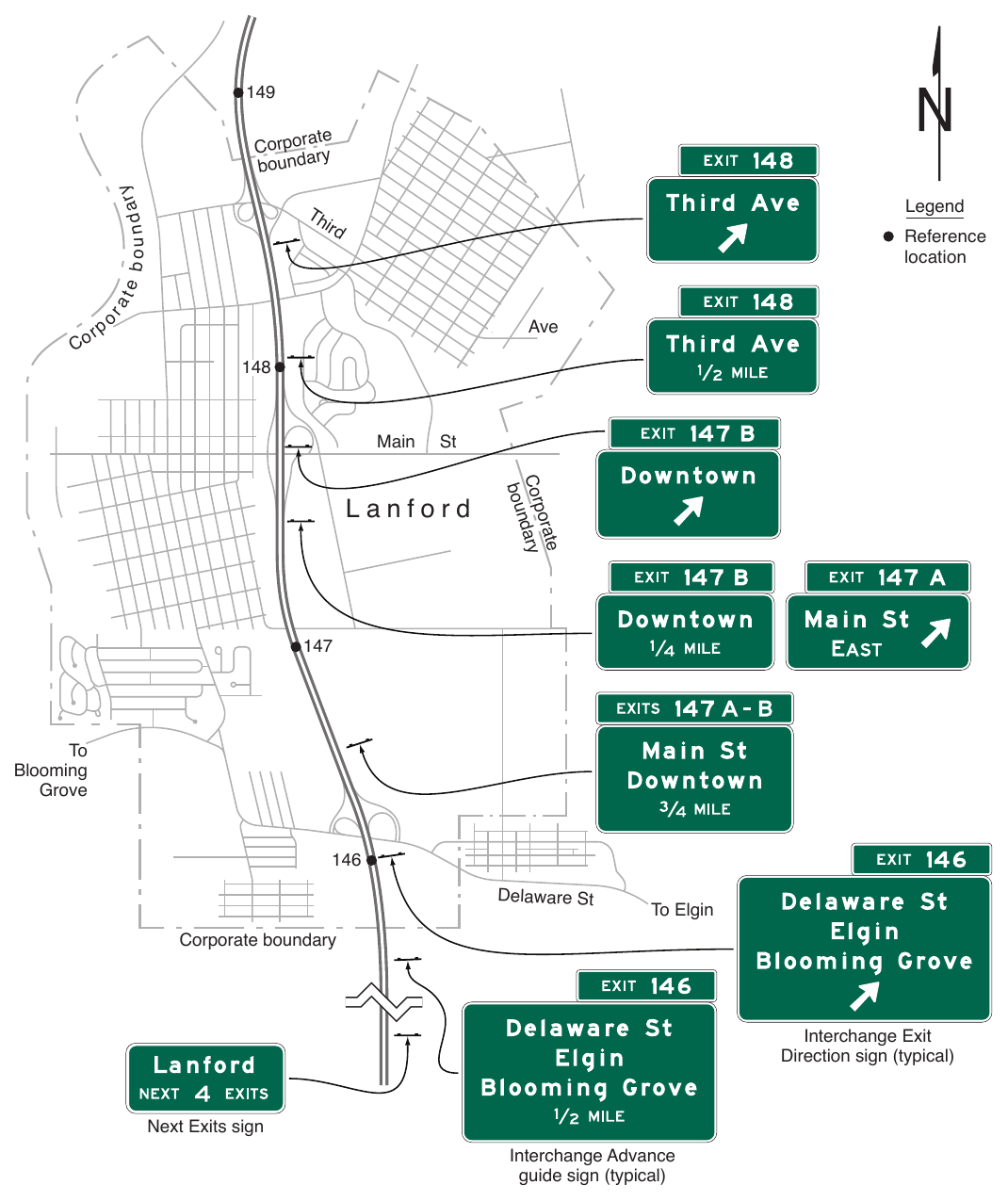
b o u n d ar y ate Corpor y r a d n u bo Legend Th ird ra te Reference location r Co po Ave
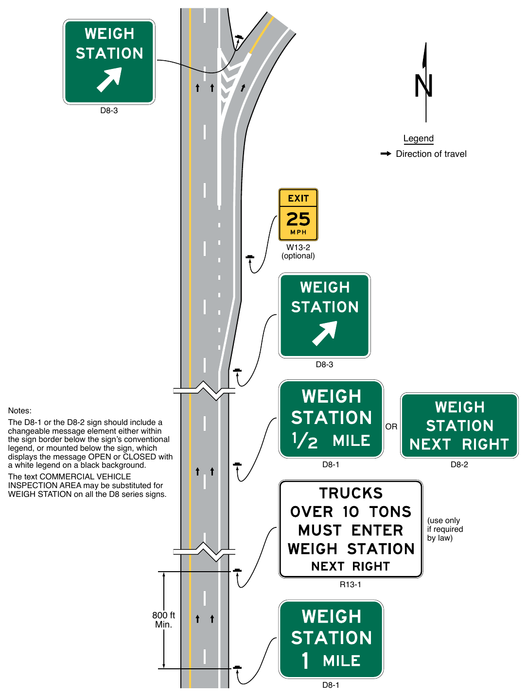
a white legend on a black background. The text COMMERCIAL VEHICLE INSPECTION AREA may be substituted for WEIGH STATION on all the D8 series signs. (use only if required by law) 800 ft Min.
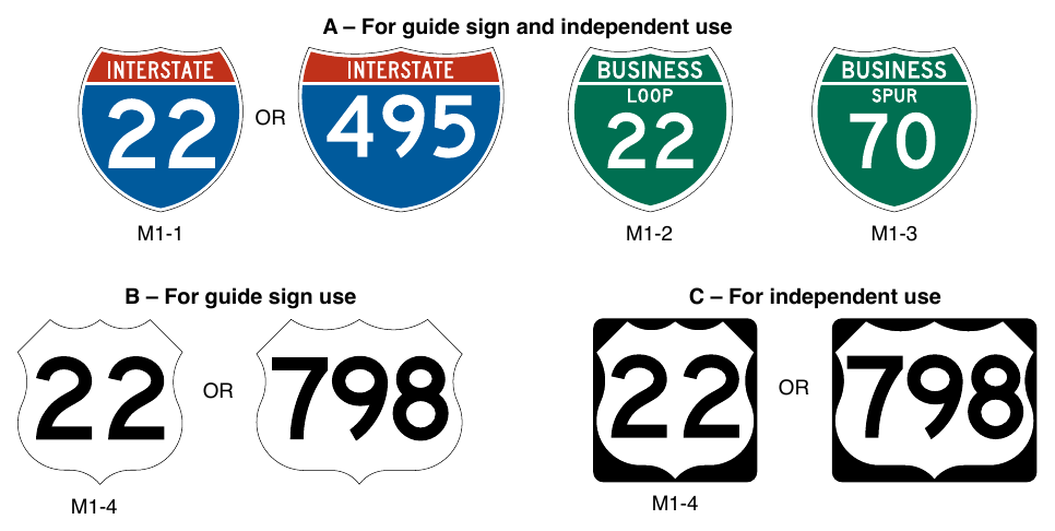
02. Route signs and auxiliary plaques showing junctions and turns should be used for guidance on approach roads, for route confirmation just beyond entrances and exits, and for reassurance along the freeway or expressway. When used along the freeway or expressway, the Route signs should be enlarged to a 36 x 36inch minimum size for route numbers with one or two digits and to a 45 x 36-inch minimum size for route numbers with three digits as shown in the “Standard Highway Signs” publication (see Section 1A.05). When independently-mounted Route signs are used in place of Pull-Through signs (see Section 2E.27), they should be located just beyond the exit.
Option
03. The standard Trailblazer Assembly (see Section 2D.34) may be used on roads leading to the freeway or expressway. Component messages of the Trailblazer Assembly may be incorporated into a single sign in accordance with the provisions of Section 2D.12. Independently-mounted Route signs may be used instead of Pull-Through signs as confirmation information.
Support
04. Section 2D.58 contains information regarding the design of signs for Auto Tour Routes.
Option
05. The commonly-used name or trailblazer route sign for a toll highway (see Chapter 2F) may be displayed on non-toll sections of the Interstate Highway System at:
- A. The last exit before entering a toll section of the Interstate Highway System;
- B. The interchange or connection with a toll highway, whether or not the toll highway is a part of the Interstate Highway System; and
- C. Other locations within a reasonable approach distance of toll highways when the name or trailblazer symbol for the toll highway would provide better guidance to road users unfamiliar with the area than would place names and route numbers.
06. The toll highway name or route sign may be included as a part of the guide sign installations on intersecting highways and approach roads to indicate the interchange with a toll section of an Interstate route. Where needed for the proper direction of traffic, a trailblazer for a toll highway that is part of the Interstate Highway System may be displayed with the Interstate Trailblazer Assembly.
Support
07. Chapter 2F contains additional information regarding signing for toll highways.
§2E.56 Eisenhower Interstate System Signs (M1-10 and M1-10a)¶
Option
01. The Eisenhower Interstate System (M1-10 and M1-10a) signs (see Figure 2E-61) may be used, in accordance with Paragraphs 2 and 3 of this Section, on Interstate highways at periodic intervals and in rest areas, scenic overlooks, or other similar roadside facilities on the Interstate Highway System.
Standard
02. If used, the M1-10a sign shall be used only in rest areas or other similar facilities where the sign can be viewed by occupants of parked vehicles or by pedestrians. The M1-10a sign shall not be installed on Interstate highway mainlines, ramps, or other roadways where it can be viewed by vehicular traffic.
03. The M1-10 and M1-10a signs shall not be used as part of a Junction, Advance Route Turn, Directional, or Trailblazer Assembly, or as part of a guide sign or similar assembly providing direction to a route or destination.
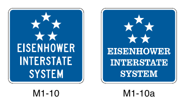
SIGNS FOR ROUTE DIVERSION BY VEHICLE CLASS¶
§2E.57 Signs for Route Diversion by Vehicle Class¶
Support
01. On some highways, a physical condition or highway feature might limit certain types or classes of vehicles from proceeding along that route through the site of that condition beyond which those vehicles are otherwise allowed. Examples include, but are not limited to, a restriction on taller legal-height vehicles through a tunnel with a low clearance; a restriction of hazardous materials through a tunnel or over a bridge; and a restriction on wider vehicles, such as large trucks, over a viaduct with narrow lanes. In such cases, the restricted vehicles might be diverted along another route to reach a destination beyond the location of the limiting condition.
Guidance
02. Where certain vehicles are prohibited at a downstream location along a route and those vehicles must divert to reach a through destination beyond that location, regulatory, warning, and/or guide signs advising those vehicle operators of the diversion should be installed in advance of the decision point to leave the through route for the diversion route.
Option
03. The interchange and pull-through guide signs for the last point at which restricted vehicles must exit may be modified to incorporate regulatory and/or warning panels with word legends to display the regulations and/or warning messages relative to the vehicle class restriction.
04. Standard post-mounted regulatory and warning signs, such as the No Hazardous Materials (R14-3) or Advance Low Clearance (W12-2) signs, may be used as provided elsewhere in this Manual at independent locations to supplement the regulatory and warning signs and panels referenced in Paragraphs 2 and 3 of this Section.
Support
05. An example of signing for a route diversion by vehicle class is shown in Figure 2E-62.
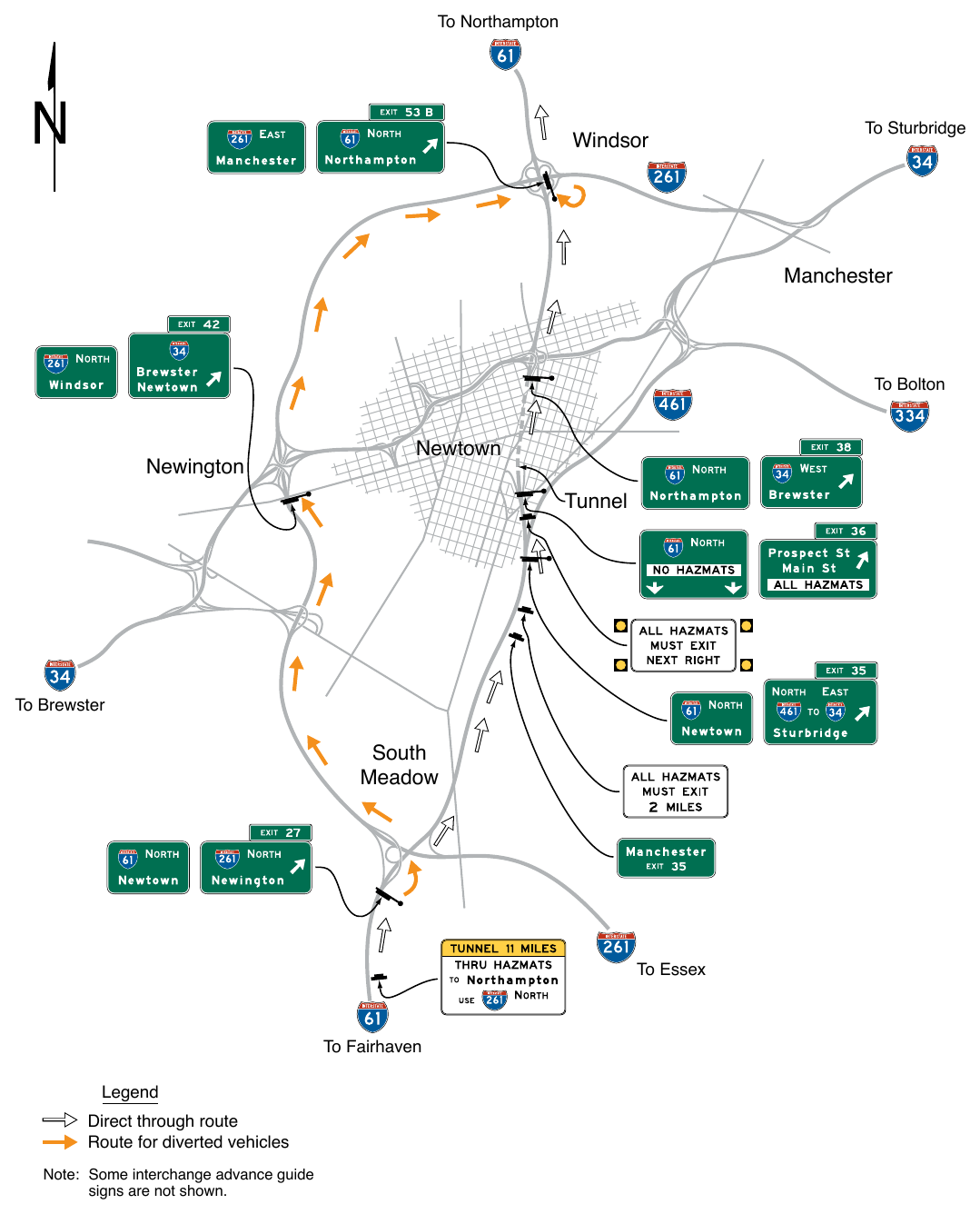
Note: Some interchange advance guide signs are not shown.
INTERFACE WITH CONVENTIONAL ROADWAYS¶
§2E.58 Signing on Conventional Road Approaches and Connecting Roadways¶
Support
01. Section 2D.49 contains information regarding the signing on conventional roads on the approaches to interchanges and the signing on connecting roadways.
§2E.59 Wrong-Way Traffic Control at Interchange Ramps¶
Support
01. Section 2B.48 contains information regarding the use of regulatory signs to deter wrong-way movements at intersections of freeway or expressway ramps with conventional roads, and in the area where entrance ramps intersect with the mainline lanes.
02. Section 2D.50 contains information regarding the use of a Directional assembly or a guide sign to mark the entrance to a freeway or expressway from a conventional road.