Chapter 4D. Design Features of Traffic Control Signals¶
§4D.01 General¶
Support
01. The features of traffic control signals of interest to road users are the location, design, and meaning of the signal indications. Uniformity in the design features that affect the traffic to be controlled, as set forth in this Manual, is especially important for the safety and efficiency of operations.
02. Traffic control signals can be operated in pretimed, semi-actuated, or full-actuated modes. For isolated (noninterconnected) signalized locations on rural high-speed highways, full-actuated mode with advance vehicle detection on the high-speed approaches is typically used. These features are designed to reduce the frequency with which the onset of the yellow change interval is displayed when high-speed approaching vehicles are in the “dilemma zone” such that the drivers of these high-speed vehicles find it difficult to decide whether to stop or proceed.
Standard
03. The design and operation of traffic control signals shall take into consideration the needs of all modes of traffic including access and safety.
04. When a traffic control signal is not in operation, such as before it is placed in service, during seasonal shutdowns, or when it is not desirable to operate the traffic control signal, the signal faces shall be covered, turned, or taken down to clearly indicate that the traffic control signal is not in operation.
Guidance
05. If a cover is placed over a traffic control signal face that is not in operation and that has a yellow retroreflective strip along the perimeter of its signal backplate (see Paragraph 21 in Section 4D.06), the entire signal face, including the backplate, should be covered. If a traffic control signal face that is not in operation and that has a yellow retroreflective strip along the perimeter of its signal backplate is turned, the turned signal face should be oriented such that the yellow backplate border will not reflect light back to road users on any of the approaches to the intersection.
Support
06. Seasonal shutdown is a condition in which a permanent traffic control signal is turned off or otherwise made non-operational during a particular season when its operation is not justified. This might be applied in a community where tourist traffic during most of the year justifies the permanent signalization, but a seasonal shutdown of the signal during an annual period of lower tourist traffic would reduce delays; or where a major traffic generator, such as a large factory, justifies the permanent signalization, but the large factory is shut down for an annual factory vacation for a few weeks in the summer.
Standard
07. A traffic control signal shall control traffic only at the intersection or midblock location where the signal faces are placed.
Guidance
08. Midblock crosswalks should not be signalized if they are located within 300 feet from the nearest traffic control signal, unless supported by an engineering study or engineering judgment that indicates safe and efficient operation of the closely-spaced traffic control signals can be achieved.
09. Midblock crosswalks should not be signalized if they are located within 100 feet from side streets or driveways that are controlled by STOP signs or YIELD signs, unless supported by an engineering study or engineering judgment that considers restricting turning movements from the side street or driveway to eliminate conflicts with pedestrian and bicyclist movements.
10. Engineering judgment should be used to determine the proper phasing and timing for a traffic control signal. Since traffic flows and patterns change, phasing and timing should be reevaluated regularly and updated if needed.
11. Traffic control signals within ½ mile of one another along a major route or in a network of intersecting major routes should be coordinated, preferably with interconnected controller units. Where traffic control signals that are within ½ mile of one another along a major route have a jurisdictional boundary or a boundary between different signal systems between them, coordination across the boundary should be considered.
Support
12. Signal coordination need not be maintained between control sections that operate on different cycle lengths.
13. Sections 4F.19, 4Q.03, and 8D.09 contain information about coordination of traffic control signals with grade crossing signals and movable bridge signals.
§4D.02 Provisions for Pedestrians¶
Support
01. Chapter 4I contains additional information regarding pedestrian control features, Chapter 4J contains additional information regarding pedestrian hybrid beacons, and Chapter 4K contains additional information regarding accessible pedestrian signals and detectors.
Standard
02. Pedestrian signal heads shall be used in conjunction with vehicular traffic control signals under any of the following conditions, unless the pedestrian crossing is prohibited:
- A. If the basis for traffic signal installation was justified by an engineering study and meeting either Warrant 4, Pedestrian Volume or Warrant 5, School Crossing (see Chapter 4C);
- B. If an exclusive pedestrian signal phase or a leading pedestrian interval (LPI) is provided with all conflicting vehicular movements being stopped;
- C. At an established signalized school crossing; or
- D. Where there are existing pedestrian accommodations and engineering judgment determines that multi-phase signal indications (such as split-phase timing) would tend to confuse or cause conflicts with pedestrians using a crosswalk guided only by vehicular signal indications.
Guidance
03. Pedestrian signal heads should be installed for each marked crosswalk at a location controlled by a traffic control signal.
04. Where pedestrian movements regularly occur, pedestrians should be provided with sufficient time to cross the roadway by adjusting the traffic control signal operation and timing to provide sufficient crossing time every cycle or by providing pedestrian detectors.
05. Where certain pedestrian movements are prohibited at a traffic control signal location, a No Pedestrian Crossing (R9-3) sign (see Section 2B.57) should be used if it is impracticable to provide a barrier or other physical feature to physically discourage the pedestrian movements.
Support
06. Accessible pedestrian signals (see Chapter 4K) that provide information in non-visual formats (such as audible tones and/or speech messages, and vibrating surfaces) enhance safety and accessibility at signalized crossings for pedestrians with vision disabilities.
Option
07. Pedestrian signal heads may be used under other conditions based on engineering judgment.
§4D.03 Provisions for Bicyclists¶
Standard
01. At installations where visibility-limited signal faces are used, signal faces shall be adjusted so bicyclists for whom the indications are intended can see the signal indications. If the visibility-limited signal faces cannot be aimed to serve the bicyclist, then separate signal faces (see Chapter 4H) shall be provided for the bicyclist.
02. On bikeways, signal timing and actuation shall be reviewed and adjusted to consider the needs of bicyclists.
Option
03. Where it is desired to provide separate signal indications to control bicyclist movements at a traffic control signal, bicycle signal faces may be used (see Chapter 4H).
Support
04. Sections 9B.02, 9B.11, 9B.20, 9B.22, 9E.02, 9E.06, 9E.07, 9E.08, 9E.11, 9E.12, and 9E.15 contain additional provisions regarding bicyclist movements and actuation at traffic control signals.
§4D.04 Provisions for Transit Vehicles¶
Option
01. Where it is desired to provide separate signal indications to control transit vehicles at a traffic control signal, LRT signal indications may be used at intersections where special signal phases are used for transit vehicles (see Section 8D.15).
§4D.05 Number of Signal Faces on an Approach¶
Standard
01. The signal faces for each approach to an intersection or a midblock location shall be provided as follows:
- A. If a signalized motor vehicle through movement exists on an approach, a minimum of two primary signal faces shall be provided for the through movement. Except for single lane approaches with a combined left-turn/right-turn lane and no through movement (see Figure 4F-15 (A)), if a signalized motor vehicle through movement does not exist on an approach, a minimum of two primary signal faces shall be provided for the signalized motor vehicle turning movement that is considered to be the major movement from the approach (also see Section 4F.16).
- B. See Sections 4F.02 through 4F.08 for left-turn (and U-turn to the left) signal faces.
- C. See Sections 4F.09 through 4F.15 for right-turn (and U-turn to the right) signal faces.
Option
02. Where a movement (or a certain lane or lanes) at the intersection never conflicts with any other signalized vehicular or pedestrian movement, a continuously-displayed single-section GREEN ARROW signal indication may be used to inform road users that the movement is free-flow and does not need to stop.
Support
03. In some circumstances where the through movement never conflicts with any other signalized vehicular or pedestrian movement at the intersection, such as at T-intersections with appropriate geometrics and/or pavement markings and signing, an engineering study might determine that the through movement (or certain lanes of the through movement) can be free-flow and not signalized.
Guidance
04. If two or more left-turn lanes are provided for a separately-controlled left-turn movement, or if a left-turn movement represents the major movement from an approach, two or more primary left-turn signal faces should be provided.
05. If two or more right-turn lanes are provided for a separately-controlled right-turn movement, or if a right-turn movement represents the major movement from an approach, two or more primary right-turn signal faces should be provided.
Support
06. Locating primary signal faces overhead on the far side of the intersection has been shown to provide safer operation by reducing intersection entries late in the yellow interval and by reducing red signal violations, as compared to post-mounting signal faces at the roadside or locating signal faces overhead within the intersection on a diagonally-oriented mast arm or span wire. On approaches with two or more lanes for the through movement, one signal face per through lane, centered over each through lane, has also been shown to provide safer operation.
Guidance
07. If the posted or statutory speed limit or the 85th-percentile speed on an approach to a signalized location is 45 mph or higher, signal faces should be provided as follows for all new or reconstructed signal installations (see Figure 4D-1):
- A. The minimum number and location of primary (non-supplemental) signal faces for through traffic should be provided in accordance with Table 4D-1.
- B. If the number of overhead primary signal faces for through traffic is equal to the number of through lanes on an approach, one overhead signal face should be located approximately over the center of each through lane.
- C. Except for shared left-turn and right-turn signal faces, any primary signal face required by Sections 4F.02 through 4F.16 for a mandatory turn lane should be located overhead approximately over the center of each mandatory turn lane.
- D. All primary signal faces should be located on the far side of the intersection.
- E. In addition to the primary signal faces, one or more supplemental pole-mounted or overhead signal faces should be considered to provide added visibility for approaching traffic that is traveling behind large vehicles.
- F. All signal faces should have backplates.
08. This layout of signal faces should also be considered for any major urban or suburban arterial street with four or more lanes and for other approaches with speeds of less than 45 mph.
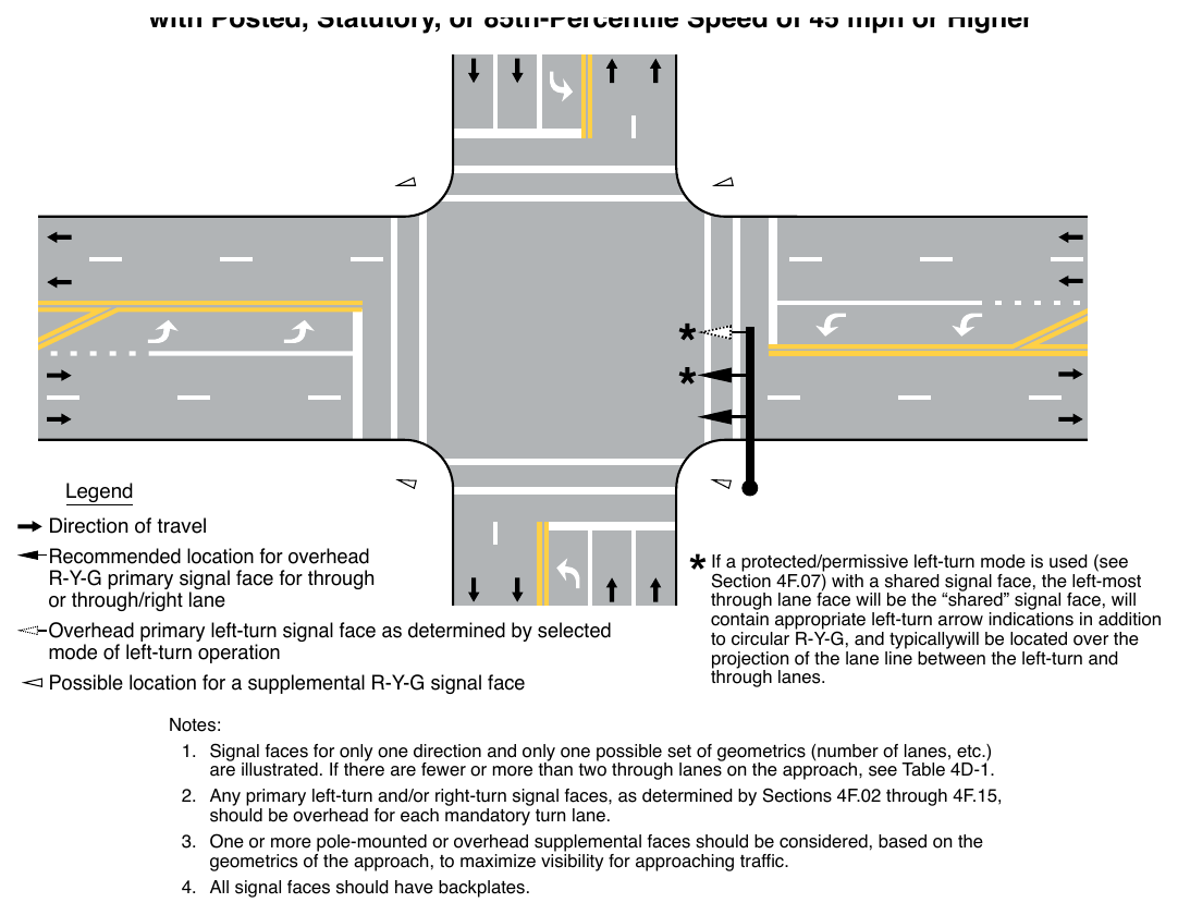
- 1. Signal faces for only one direction and only one possible set of geometrics (number of lanes, etc.) are illustrated. If there are fewer or more than two through lanes on the approach, see Table 4D-1.
- 2. Any primary left-turn and/or right-turn signal faces, as determined by Sections 4F.02 through 4F.15, should be overhead for each mandatory turn lane.
- 3. One or more pole-mounted or overhead supplemental faces should be considered, based on the geometrics of the approach, to maximize visibility for approaching traffic.
- 4. All signal faces should have backplates.
Table 4D-1. Recommended Minimum Number of Primary Signal Faces for Through Traffic on Approaches with Posted, Statutory, or 85th-Percentile Speed of 45 mph or Higher
| Number of Through Lanes on the Approach | Total Number of Primary Through Signal Faces for the Approach* | Minimum Number of Overhead-Mounted Primary Through Signal Faces for the Approach |
|---|---|---|
| 1 | 2 | 1 |
| 2 | 2 | 1 |
| 3 | 3 | 2** |
| 4 or more | 4 or more | 3** |
Notes: * A minimum of two through signal faces is always required (see Section 4D.05). These recommended numbers of through signal faces may be exceeded. Also, see cone of vision requirements otherwise indicated in Section 4D.07.
** If practical, all of the recommended number of primary through signal faces should be located overhead.
numbers of through signal faces may be exceeded. Also, see cone of vision requirements otherwise indicated in Section 4D.07. located overhead.
§4D.06 Visibility, Aiming, and Shielding of Signal Faces¶
Guidance
01. The visibility of signal indications to approaching traffic should be the highest priority for signal face placement and aiming.
02. Road users approaching a signalized intersection or other signalized area, such as a midblock crosswalk, should be given a clear and unmistakable indication of whether they are being directed to stop or permitted to proceed.
03. The geometry of each intersection to be signalized, including vertical grades, horizontal curves, and obstructions as well as the lateral and vertical angles of sight toward a signal face, as determined by typical driver-eye position, should be considered in determining the vertical, longitudinal, and lateral position of the signal face.
04. At signalized midblock crosswalks, at least one of the signal faces should be over the traveled way for each approach.
05. The two primary signal faces required as a minimum for each approach should be continuously visible to traffic approaching the traffic control signal, from a point at least the minimum sight distance provided in Table 4D-2 in advance of and measured to the stop line. This range of continuous visibility should be provided unless precluded by a physical obstruction or unless another signalized location is within this range.
Table 4D-2. Minimum Sight Distance for Signal Visibility
| 85th-Percentile Speed | Minimum Sight Distance |
|---|---|
| 20 mph | 175 feet |
| 25 mph | 215 feet |
| 30 mph | 270 feet |
| 35 mph | 325 feet |
| 40 mph | 390 feet |
| 45 mph | 460 feet |
| 50 mph | 540 feet |
| 55 mph | 625 feet |
| 60 mph | 715 feet |
Note: Distances in this table are derived from stopping sight distance plus an assumed queue length for shorter cycle lengths (60 to 75 seconds).
06. If approaching traffic does not have a continuous view of at least two signal faces for at least the minimum sight distance shown in Table 4D-2, a sign (see Section 2C.35) should be installed to warn approaching traffic of the traffic control signal.
Option
07. If a sign is installed to warn approaching road users of the traffic control signal, the sign may be supplemented by a Warning Beacon (see Section 4S.03).
08. A Warning Beacon used in this manner may be interconnected with the traffic signal controller assembly in such a manner as to flash yellow during the period when road users passing this beacon at the legal speed for the roadway might encounter a red signal indication (or a queue resulting from the display of the red signal indication) upon arrival at the signalized location.
09. If the sight distance to the signal faces for an approach is limited by horizontal or vertical alignment, supplemental signal faces aimed at a point on the approach at which the signal indications first become visible may be used.
Guidance
10. Supplemental signal faces should be used if engineering judgment has shown that they are needed to achieve intersection visibility both in advance and immediately before the signalized location.
11. If supplemental signal faces are used, they should be located to provide optimum visibility for the movement to be controlled.
12. In cases where irregular street design necessitates placing signal faces for different street approaches with a comparatively small angle between their respective signal indications, each signal indication should, to the extent practical, be visibility-limited by signal visors, signal louvers, or other means so that an approaching road user’s view of the signal indication(s) controlling movements on other approaches is minimized.
Standard
13. Signal visors exceeding 12 inches in length shall not be used on free-swinging signal faces.
Guidance
14. Signal visors should be used on signal faces to aid in directing the signal indication specifically to approaching traffic, as well as to reduce “sun phantom,” which can result when external light enters the lens.
15. The use of signal visors, or the use of signal faces or devices that direct the light without a reduction in intensity, should be considered as an alternative to signal louvers because of the reduction in light output caused by signal louvers.
Option
16. Special signal faces, such as visibility-limited signal faces, may be used such that the road user does not see signal indications intended for other approaches before seeing the signal indications for their own approach, especially if simultaneous viewing of both signal indications could cause the road user to be misdirected.
Guidance
17. If the posted or statutory speed limit or the 85th-percentile speed on an approach to a signalized location is 45 mph or higher, signal backplates should be used on all of the signal faces that face the approach. Signal backplates should also be considered for use on signal faces on approaches with posted or statutory speed limits or 85th-percentile speeds of less than 45 mph where sun glare, bright sky, and/or complex or confusing backgrounds indicate a need for enhanced signal face target value.
Support
18. The use of backplates enhances the contrast between the traffic signal indications and their surroundings for both day and night conditions, which is also helpful to older drivers.
Standard
19. If backplates are used, ancillary legends of any kind that identify the purpose or operation of the signal face shall not be placed on the backplate.
20. The inside of signal visors (hoods), the entire surface of louvers and fins, and the front surface of backplates shall have a dull black finish to minimize light reflection and to increase contrast between the signal indication and its background.
Option
21. A yellow retroreflective strip with a minimum width of 1 inch and a maximum width of 3 inches may be placed along the perimeter of the face of a signal backplate to project a rectangular appearance at night.
§4D.07 Lateral Positioning of Signal Faces¶
Standard
01. At least one and preferably both of the minimum of two primary signal faces required for the through movement (or the major turning movement if there is no through movement) on the approach shall be located between two lines intersecting with the center of the approach at a point 10 feet behind the stop line, one making an angle of approximately 20 degrees to the right of the center of the approach extended, and the other making an angle of approximately 20 degrees to the left of the center of the approach extended. The signal face that satisfies this requirement shall simultaneously satisfy the longitudinal placement requirement described in Section 4D.08 (see Figure 4D-2).
02. If both of the minimum of two primary signal faces required for the through movement (or the major turning movement if there is no through movement) on the approach are post-mounted, they shall both be on the far side of the intersection, one on the right and one on the left of the approach lane(s).
03. The required signal faces for through traffic on an approach shall be located not less than 8 feet apart measured horizontally perpendicular to the approach between the centers of the signal faces.
04. If more than one separate turn signal face is provided for a turning movement and if one or both of the separate turn signal faces are located over the roadway, the signal faces shall be located not less than 8 feet apart measured horizontally perpendicular to the approach between the centers of the signal faces.
Guidance
05. If horizontally-arranged or clustered signal faces are used, the minimum 8-foot horizontal separation between the two signal faces should be measured from the center of the right-most signal indication in the signal face on the left to the center of the left-most signal indication in the signal face on the right.
06. Except as provided in Paragraph 7 of this Section, for signal faces located over the roadway, separate turn signal faces should be located at least 8 feet from the nearest traffic signal face for a different movement on the same approach measured horizontally perpendicular to the approach between the centers of the signal faces.
Option
07. For modifications to existing traffic signals, the minimum horizontal separation between a separate turn signal face and the nearest traffic signal face for a different movement may be reduced to 3 feet.
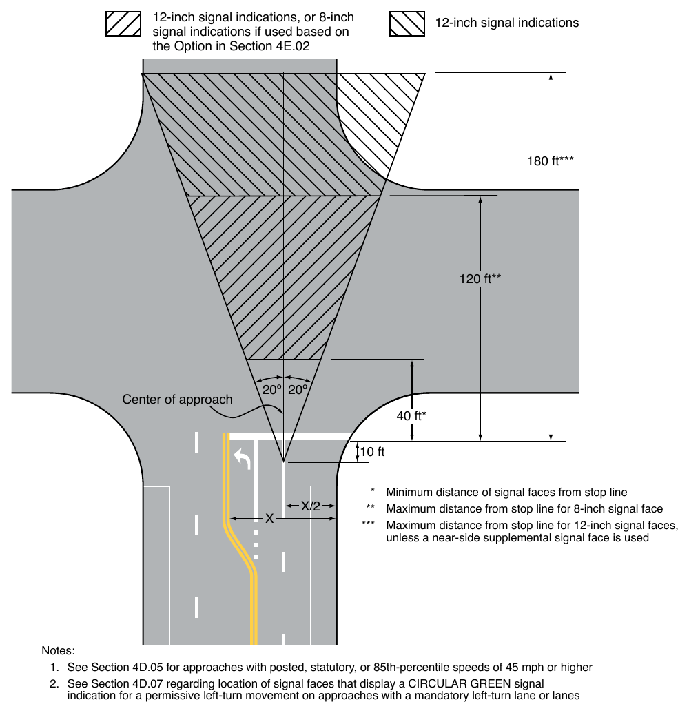
Location of primary signal faces within these areas: 12-inch signal indications, or 8-inch signal indications if used based on the Option in Section 4E.02 12-inch signal indications 180 ft 120 ft Center of approach 20º 20º 40 ft 10 ft unless a near-side supplemental signal face is used Notes:
- 1. See Section 4D.05 for approaches with posted, statutory, or 85th-percentile speeds of 45 mph or higher
- 2. See Section 4D.07 regarding location of signal faces that display a CIRCULAR GREEN signal indication for a permissive left-turn movement on approaches with a mandatory left-turn lane or lanes
Guidance
If a signal face controls a specific lane or lanes of an approach, its position should make it readily visible to road users making that movement.
Support
09. Section 4D.05 contains additional provisions regarding lateral positioning of signal faces for approaches having a posted or statutory speed limit or an 85th-percentile speed of 45 mph or higher.
Guidance
10. If a mandatory left-turn, right-turn, or U-turn lane is present on an approach and if a primary separate turn signal face controlling that lane is mounted over the roadway, the primary separate turn signal face should not be positioned any farther to the right than the extension of the right-hand edge of the mandatory turn lane or any farther to the left than the extension of the left-hand edge of the mandatory turn lane.
Support
11. Supplemental turn signal faces mounted over the roadway are not subject to the positioning recommendations in Paragraph 10 of this Section.
Guidance
12. For new or reconstructed signal installations, on an approach with a mandatory turn lane(s) for a permissive left-turn (or U-turn to the left) movement, signal faces that display a CIRCULAR GREEN signal indication should not be post-mounted on the far-side median or mounted overhead above the mandatory turn lane(s) or the extension of the lane(s).
Standard
13. If supplemental post-mounted signal faces are used, the following limitations shall apply:
- A. Left-turn arrows and U-turn arrows to the left shall not be used in near right signal faces that are located to the right of the through and/or right-turn lanes.
- B. Right-turn arrows and U-turn arrows to the right shall not be used in far left signal faces that are located to the left of the through and/or left-turn lanes. A far-side median-mounted signal face shall be considered a far left signal face for this application.
§4D.08 Longitudinal Positioning of Signal Faces¶
Standard
01. Except where the width of an intersecting roadway or other conditions make it physically impractical, the signal faces for each approach to an intersection or a midblock location shall be provided as follows:
- A. A signal face installed to satisfy the requirements for primary left-turn signal faces (see Sections 4F.02 through 4F.08) and primary right-turn signal faces (see Sections 4F.09 through 4F.15), and at least one and preferably both of the minimum of two primary signal faces required for the through movement (or the major turning movement if there is no through movement) on the approach shall be located:
- 1. No less than 40 feet beyond the stop line, and
- 2. No more than 180 feet beyond the stop line unless a supplemental near-side signal face is provided.
- B. The primary signal faces that are used to satisfy the requirements of Item A shall simultaneously satisfy the lateral placement requirement described in Section 4D.07 (see Figure 4D-2).
Guidance
02. Where the nearest signal face is located between 150 and 180 feet beyond the stop line, engineering judgment of the conditions, including the worst-case visibility conditions, should be used to determine if the provision of a supplemental near-side signal face would be beneficial.
03. Supplemental near-side signal faces should be located as near as practicable to the stop line.
Support
04. Section 4D.05 contains additional provisions regarding longitudinal positioning of signal faces for approaches having a posted or 85th-percentile speed of 45 mph or higher.
§4D.09 Mounting Height of Signal Faces¶
Standard
01. The bottom of the signal housing and any related attachments to a vehicular signal face located over any portion of a highway that can be used by motor vehicles shall be at least 15 feet above the pavement.
02. The bottom of the signal housing (including brackets) of a vehicular signal face that is vertically arranged or horizontally arranged and not located over a roadway:
- A. Shall be a minimum of 8 feet above the sidewalk or, if there is no sidewalk, above the pavement grade at the center of the roadway.
- B. Shall be a minimum of 4.5 feet above the median island grade of a center median island if located on the near side of the intersection.
Guidance
03. The top of the signal housing of a vehicular signal face located over any portion of a highway that can be used by motor vehicles should not be more than 25.6 feet above the pavement.
04. For viewing distances between 40 and 53 feet from the stop line, the maximum mounting height to the top of the signal housing of a vehicular signal face located over any portion of a highway that can be used by motor vehicles should be as shown in Figure 4D-3.
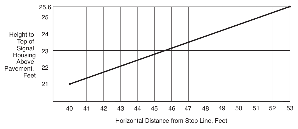
Pavement, 22 Feet
53. Horizontal Distance from Stop Line, Feet The bottom of the signal housing (including brackets) of a vehicular signal face that is vertically arranged and not located over a roadway or shoulder:
- A. Should be a maximum of 19 feet above the sidewalk or, if there is no sidewalk, above the pavement grade at the center of the roadway.
- B. Should be a maximum of 19 feet above the median island grade of a center median island if located on the near side of the intersection.
06. The bottom of the signal housing (including brackets) of a vehicular signal face that is horizontally arranged and not located over a roadway or shoulder:
- A. Should be a maximum of 22 feet above the sidewalk or, if there is no sidewalk, above the pavement grade at the center of the roadway.
- B. Should be a maximum of 22 feet above the median island grade of a center median island if located on the near side of the intersection.
§4D.10 Lateral Offset (Clearance) of Signal Faces¶
Guidance
01. Signal faces mounted at the side of a roadway at less than 15 feet from the bottom of the housing and any related attachments should have a horizontal offset of not less than 2 feet from the face of a vertical curb, or if there is no curb, not less than 2 feet from the edge of a shoulder.
§4D.11 Temporary and Portable Traffic Control Signals¶
Support
01. A temporary traffic control signal is generally installed using methods that minimize the costs of installation, relocation, and/or removal. Typical temporary traffic control signals are for specific purposes, such as for one-lane, two-way facilities in temporary traffic control zones (see Chapter 4O), for a haul-road intersection, or for access to a site that will have a permanent access point developed at another location in the near future. Portable traffic signals are temporary traffic signals.
02. Because a portable traffic control signal is considered to be a type of temporary traffic control signal, the provisions for temporary traffic control signals are also applicable to portable traffic control signals.
Standard
03. Advance signing shall be used when employing a temporary traffic control signal.
04. A temporary traffic control signal shall:
- A. Meet the physical display and operational requirements of a conventional traffic control signal;
- B. Be removed when no longer needed; and
- C. Except as provided in Paragraph 5 of this Section, be placed in the flashing mode during periods when it is not desirable to operate the signal in the steady mode, or the signal heads shall be covered, turned, or taken down to indicate that the signal is not in operation.
Option
05. If the temporary traffic control signal is capable of being operated in a semi-actuated mode, such that green signal indications are continually shown to major-street traffic except when responding to a minor-street approach vehicle call, it may be operated in a semi-actuated mode instead of being placed in a flashing mode.
Guidance
06. A temporary traffic control signal should be used only if engineering judgment indicates that installing the signal will improve the overall safety and/or operation of the location.
07. The use of temporary traffic control signals by a work crew on a regular basis in their work area should be subject to the approval of the jurisdiction having authority over the roadway.
08. A temporary traffic control signal should not operate longer than 30 days unless associated with a longerterm temporary traffic control zone project.
Support
09. Section 6L.01 contains information about the use of temporary traffic control signals in temporary traffic control zones.