2D. Guide Signs: Conventional Roads¶
Chapter 2D. GUIDE SIGNS—CONVENTIONAL ROADS¶
GENERAL DESIGN¶
§2D.01 Scope of Conventional Road Guide Sign Standards and Application¶
Standard
01. The provisions of this Chapter shall apply to any road or street other than expressways and freeways, except as otherwise provided in this Manual.
Support
02. Guide signs direct road users along streets and highways; inform them of intersecting routes; direct them to cities, towns, villages, or other important destinations; identify nearby rivers and streams, parks, forests, and historical sites; and provide information that will help them along their way in the most simple and direct manner possible.
Guidance
03. The selection of primary or control destinations (those displayed consistently over longer distances along a route) displayed on guide signs should be meaningful to road users in navigation and orientation. The destinations selected should be identifiable on official maps.
04. The familiarity of the road users with the road should be considered in determining the need for guide signs on low-volume roads.
Support
05. Low-volume roads generally do not require guide signs to the extent that they are needed on higher classes of roads. Because guide signs are typically only beneficial as a navigational aid for road users who are unfamiliar with a low-volume road, guide signs might not be needed on low-volume roads that serve only local traffic.
06. Guide signs, other than Street Name signs, generally are not used on low-volume rural roads except as needed to guide road users back to the major roadways.
Guidance
07. If used on low-volume roads, destination names should be as specific and descriptive as possible. Destinations such as campgrounds, ranger stations, recreational areas, and the like should be clearly indicated so that they are not interpreted to be communities or locations with road user services.
Option
08. Guide signs may be used on low-volume roads at intersections to provide information for road users returning to a higher class of roads.
Support
09. Chapter 2A addresses placement, location, and other general criteria for signs.
§2D.02 Color, Retroreflection, and Illumination¶
Support
01. Requirements for illumination, retroreflection, and color are stated under the specific headings for individual guide signs or groups of signs. General provisions are given in 2A.06, 2A.21, and 2A.22.
Standard
02. Except as otherwise provided in this Manual for individual signs or groups of signs, guide signs on streets and highways shall have a white message and border on a green background. All messages, borders, and legends shall be retroreflective and all backgrounds shall be retroreflective or illuminated.
Support
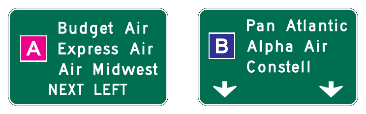
03. Color coding is sometimes used to help road users distinguish between multiple potentially confusing destinations. Examples of valuable uses of color coding include guide signs for roadways approaching or inside an airport property with multiple terminals serving multiple airlines, and community wayfinding guide signs for various traffic generator destinations within a community or area.
Standard
04. Except as otherwise provided in this Manual, different color sign backgrounds shall not be used to provide color coding of destinations. The color coding shall be accomplished by the use of different colored square or rectangular sign panels on the face of the guide signs (see Figure 2D-1).
Option
05. The different colored sign panels on the face of a sign may include a black or white (whichever provides the better contrast with the panel color) letter, numeral, or other appropriate designation to identify an airport terminal or other destination.
Support
06. Section 2D.55 contains specific provisions regarding Community Wayfinding guide signs.
§2D.03 Size of Signs¶
Standard
01. Except as provided in Section 2A.07, the minimum sizes of conventional road guide signs that have standardized designs shall be as shown in Table 2D-1.
Support
02. Section 2A.07 contains information regarding the applicability of the various columns in Table 2D-1.
Option
03. Signs larger than those shown in Table 2D-1 may be used (see Section 2A.07).
Support
04. For other guide signs, the legends are so variable that a standardized design or size is not appropriate. The sign size is determined primarily by the length of the message, and the size of lettering and spacing necessary for proper legibility.
Option
05. Reduced letter height, reduced interline spacing, and reduced edge spacing may be used on guide signs if sign size must be limited by factors such as lane width or vertical or lateral clearance.
Guidance
06. Reduced spacing between the letters or words on a line of legend should not be used as a means of reducing the overall size of a guide sign, except where determined necessary by engineering judgment to meet unusual lateral-space constraints. In such cases, the legibility distance of the sign legend should be the primary consideration in determining whether to reduce the spacing between the letters or the words or between the words and the sign border, or to reduce the letter height.
07. When a reduction in the prescribed size is necessary, the design used should be as similar as possible to the design for the standard size.
§2D.04 Lettering Style¶
Standard
01. The design of upper-case letters, lower-case letters, numerals, route shields, and spacing shall be as provided in the “Standard Highway Signs” publication (see Section 1A.05).
02. The lettering for names of places, streets, and highways on conventional road guide signs shall be a combination of lower-case letters with initial upper-case letters (see Section 2A.08). The nominal loop height of the lower-case letters shall be ¾ the height of the initial upper-case letter. When a mixed-case legend letter height is specified referring only to the initial upper-case letter, the height of the lower-case letters that follow shall be determined by this proportion. When the height of a lower-case letter is referenced, the reference is made to the nominal loop height. The height of the initial upper-case letter shall also be determined by this proportion.
03. All other word legends on conventional road guide signs shall be in upper-case letters.
04. The unique letter forms for each of the Standard Alphabet series shall not be stretched, compressed, warped, or otherwise manipulated. Modifications to the length of a word for a given letter height and series shall be accomplished only by the methods described in Section 2D.03.
Table 2D-1. Conventional Road Guide Sign and Plaque Sizes (Sheet 1 of 2)
| Sign or Plaque | Designation | Section | Conventional Road | Minimum | Oversized |
|---|---|---|---|---|---|
| Interstate Route (1 or 2 digits) | M1-1,1a | 2D.11 | 24 x 24 | — | 36 x 36 |
| Interstate Route (3 digits) | M1-1,1a | 2D.11 | 30 x 24 | — | 45 x 36 |
| Off-Interstate Route (1 or 2 digits) | M1-2,3 | 2D.11 | 24 x 24 | — | 36 x 36 |
| Off-Interstate Route (3 digits) | M1-2,3 | 2D.11 | 30 x 24 | — | 45 x 36 |
| U.S. Route (1 or 2 digits) | M1-4 | 2D.11 | 24 x 24 | — | 36 x 36 |
| U.S. Route (3 digits) | M1-4 | 2D.11 | 30 x 24 | — | 45 x 36 |
| State Route (1 or 2 digits) | M1-5 | 2D.11 | 24 x 24 | — | 36 x 36 |
| State Route (3 digits) | M1-5 | 2D.11 | 30 x 24 | — | 45 x 36 |
| County Route | M1-6 | 2D.11 | 24 x 24 | — | 36 x 36 |
| Forest Route | M1-7 | 2D.11 | 24 x 24 | 18 x 18 | 36 x 36 |
| Junction (plaque) | M2-1P | 2D.13 | 21 x 15 | — | 30 x 21 |
| Combination Junction (2 route signs) | M2-2 | 2D.14 | 60 x 48* | — | — |
| Cardinal Direction (plaque) | M3-1P,2P,3P,4P | 2D.15 | 24 x 12 | — | 36 x 18 |
| Alternate (plaque) | M4-1P,1aP | 2D.17 | 24 x 12 | — | 36 x 18 |
| By-Pass (plaque) | M4-2P | 2D.18 | 24 x 12 | — | 36 x 18 |
| Business (plaque) | M4-3P | 2D.19 | 24 x 12 | — | 36 x 18 |
| Truck (plaque) | M4-4P | 2D.20 | 24 x 12 | — | 36 x 18 |
| To (plaque) | M4-5P | 2D.21 | 24 x 12 | — | 36 x 18 |
| End (plaque) | M4-6P | 2D.22 | 24 x 12 | — | 36 x 18 |
| Temporary (plaque) | M4-7P,7aP | 2D.24 | 24 x 12 | — | 36 x 18 |
| Emergency Route | M4-11 | 2D.59 | 30 x 30 | — | — |
| Emergency Route | M4-11a | 2D.59 | 30 x 30 | — | — |
| Emergency Route To (plaque) | M4-11bP, 11cP | 2D.59 | 30 x 18 | — | — |
| End Emergency Route | M4-12 | 2D.59 | 24 x 18 | — | — |
| Begin (plaque) | M4-14P | 2D.23 | 24 x 12 | — | 36 x 18 |
| Advance Turn Arrow (plaque) | M5-1P,2P,3P | 2D.26 | 21 x 15 | — | 30 x 21 |
| Lane Designation (plaque) | M5-4P,5P,6P | 2D.27 | 24 x 18 | — | 36 x 24 |
| Directional Arrow (plaque) | M6-1P,2P,2aP, 3P,4P,5P,6P,7P | 2D.28 | 21 x 15 | — | 30 x 21 |
| National Scenic Byway | M10-1 | 2D.57 | 24 x 24 | — | — |
| National Scenic Byway (plaque) | M10-1aP | 2D.57 | 24 x 12 | — | — |
| Byway Identification | M10-2 | 2D.58 | 24 x 24 | — | — |
| Byway Identification (plaque) | M10-2aP | 2D.58 | 24 x 12 | — | — |
| State Scenic Byway System | M10-3 | 2D.58 | 24 x 24 | — | — |
| State Scenic Byway - Simple Graphic and Byway Identification | M10-3a | 2D.58 | 24 x 24 | — | — |
| Scenic Byway (plaque) | M10-3bP | 2D.58 | 24 x 12 | — | — |
| National Historic Trail - Identification | M11-1 | 2D.58 | 24 x 24 | — | — |
| National Historic Trail - Historic Route (plaque) | M11-1aP | 2D.58 | 24 x 12 | — | — |
| National Historic Trail - Crossing (plaque) | M11-1bP | 2D.58 | 24 x 12 | — | — |
| National Historic Trail - Auto Tour Route (plaque) | M11-1cP | 2D.58 | 24 x 12 | — | — |
| National Historic Trail - Distance (plaque) | M11-1dP | 2D.58 | 24 x 12 | — | — |
| Destination (1 line) | D1-1 | 2D.36 | Varies x 18 | — | — |
| Destination and Distance (1 line) | D1-1a | 2D.36 | Varies x 18 | — | — |
| Circular Intersection Destination (1 line) | D1-1d | 2D.39 | Varies x 18 | — | — |
| Circular Intersection Departure Guide | D1-1e | 2D.39 | Varies x 42* | — | — |
| Destination (2 lines) | D1-2 | 2D.36 | Varies x 30 | — | — |
| Destination and Distance (2 lines) | D1-2a | 2D.36 | Varies x 30 | — | — |
| Circular Intersection Destination (2 lines) | D1-2d | 2D.39 | Varies x 30 | — | — |
Table 2D-1. Conventional Road Guide Sign and Plaque Sizes (Sheet 2 of 2)
| Sign or Plaque | Designation | Section | Conventional Road | Minimum | Oversized |
|---|---|---|---|---|---|
| Destination (3 lines) | D1-3 | 2D.36 | Varies x 42 | — | — |
| Destination and Distance (3 lines) | D1-3a | 2D.36 | Varies x 42 | — | — |
| Circular Intersection Destination (3 lines) | D1-3d | 2D.39 | Varies x 42 | — | — |
| Circular Intersection Diagrammatic Destination | D1-5 | 2D.39 | Varies x 72* | — | — |
| Circular Intersection Diagrammatic Destination, Right-Turn Bypass | D1-5a | 2D.39 | Varies x 78* | — | — |
| Distance (1 line) | D2-1 | 2D.43 | Varies x 18 | — | — |
| Distance (2 lines) | D2-2 | 2D.43 | Varies x 30 | — | — |
| Distance (3 lines) | D2-3 | 2D.43 | Varies x 42 | — | — |
| Street Name (1 line) | D3-1,1a | 2D.45 | Varies x 12 | Varies x 8 | Varies x 18 |
| Overhead Street Name (1 line) | D3-1,1a | 2D.45 | Varies x 24 | — | — |
| Street Name (2 lines) | D3-1,1a | 2D.45 | Varies x 24 | Varies x 15 | Varies x 33 |
| Overhead Street Name (2 lines) | D3-1,1a | 2D.45 | Varies x 48 | — | — |
| Advance Street Name (2 lines) | D3-2 | 2D.46 | Varies x 30 | — | — |
| Advance Street Name (3 lines) | D3-2 | 2D.46 | Varies x 42 | — | — |
| Advance Street Name (4 lines) | D3-2 | 2D.46 | Varies x 54 | — | — |
| Parking Area Directional | D4-1 | 2D.47 | 30 x 24 | 18 x 15 | — |
| Park - Ride | D4-2 | 2D.48 | 30 x 36 | 24 x 30 | 36 x 48 |
| Advance Weigh Station Distance | D8-1 | 2D.51 | 78 x 60 | 60 x 48 | 96 x 72 |
| Weigh Station Ahead | D8-1a | 2D.51 | 66 x 48 | 48 x 36 | — |
| Weigh Station Advance Direction | D8-2 | 2D.51 | 84 x 72 | 66 x 54 | 108 x 90 |
| Weigh Station Entrance Direction | D8-3 | 2D.51 | 66 x 60 | 48 x 42 | 84 x 78 |
| Crossover | D13-1,2 | 2D.52 | 60 x 30 | — | 78 x 42 |
| Freeway Entrance | D13-3 | 2D.50 | 48 x 30 | — | — |
| Freeway Entrance (Directional) | D13-3a | 2D.50 | 48 x 42 | — | — |
| Combination Lane Use / Destination | D15-1 | 2D.38 | Varies x 96 | — | — |
| Next Truck Lane | D17-1 | 2D.53 | 42 x 48 | — | 60 x 66 |
| Advance Truck Lane | D17-2 | 2D.53 | 42 x 42 | — | 60 x 54 |
| Next Passing Lane | D17-3 | 2D.53 | 42 x 48 | — | 60 x 66 |
| Advance Passing Lane | D17-4 | 2D.53 | 42 x 42 | — | 60 x 54 |
| Advance Emergency Turn-Out | D17-5 | 2D.54 | 60 x 36 | — | 78 x 54 |
| Emergency Turn-Out (Directional) | D17-6 | 2D.54 | 60 x 36 | — | 78 x 60 |
| Advance Slow Vehicle Turn-Out | D17-7 | 2D.54 | 72 x 36 | — | 96 x 54 |
*The size shown is for a typical sign. The size should be determined based on the amount of legend required for the sign. Notes: 1. Larger signs may be used when appropriate 2. Dimensions in inches are shown as width x height
*The size shown is for a typical sign. The size should be determined based on the amount of legend required for the sign. Notes: 1. Larger signs may be used when appropriate
- 2. Dimensions in inches are shown as width x height
§2D.05 Size of Lettering¶
Support
01. Sign legibility is a direct function of letter size and spacing. Legibility distance has to be sufficient to give road users enough time to read and comprehend the sign. Under optimum conditions, a guide sign message can be read and understood in a brief glance. The legibility distance takes into account factors such as inattention, blocking of view by other vehicles, unfavorable weather, inferior eyesight, or other causes for delayed or slow reading. Where conditions permit, repetition of guide information on successive signs gives the road user more than one opportunity to obtain the information needed.
Standard
02. Design layouts for conventional road guide signs showing interline spacing, edge spacing, and other specification details shall be as shown in the “Standard Highway Signs” publication (see Section 1A.05).
03. Except as otherwise provided in this Manual, the principal legend on post-mounted guide signs shall be in letters and numerals at least 6 inches in height for all upper-case letters, or a combination of 6 inches in height for upper-case letters and 4.5 inches in nominal loop height (see Section 2D.04) for lower-case letters. On low-volume roads with speeds of 25 mph or less, and on urban streets with speeds of 25 mph or less, the principal legend on post-mounted guide signs shall be in letters at least 4 inches in height for all upper-case letters, or a combination of 4 inches in height for upper-case letters and 3 inches in nominal loop height for lower-case letters.
04. Except as otherwise provided in this Manual, the principal legend on overhead guide signs shall be in letters and numerals at least 6 inches in height for all upper-case letters, or a combination of 6 inches in height for upper-case letters and 4.5 inches in nominal loop height (see Section 2D.04) for lower-case letters.
Guidance
05. Lettering sizes should be consistent on any particular class of highway.
06. The minimum lettering and numeral sizes provided in this Manual (see Table 2D-2) should be exceeded where conditions indicate a need for greater legibility.
§2D.06 Amount of Legend¶
Support
01. The longer the legend on a guide sign, the longer it will take road users to recognize and comprehend it, regardless of letter size.
Guidance
02. Except where otherwise provided in this Manual, guide signs should be limited to no more than three lines of destinations, which include place names, route numbers, street names, and cardinal directions. Where two or more signs are included in the same overhead display, the amount of legend should be further minimized. Where appropriate, a distance message or action information, such as an exit number, NEXT RIGHT, or directional arrows, should be provided on guide signs in addition to the destinations.
§2D.07 Abbreviations¶
Support
01. The use of commonly recognized abbreviations for certain words can be useful in reducing the reading time and improve quicker comprehension of a sign message. Descriptors and directional or quadrant orientations for street names and destinations, such as Boulevard (Blvd), North (N), and Southwest (SW), are some examples of commonly recognized abbreviations. Examples of the use of some guide sign abbreviations are shown in Figure 2D-2.
Standard
02. The words NORTH, SOUTH, EAST, and WEST shall not be abbreviated when used to indicate cardinal directions of numbered or named highways on guide signs.
Guidance
03. Abbreviations should be kept to a minimum; however, they are useful when complete destination messages produce excessively long signs. If used, abbreviations should be unmistakably recognized by road users (see Section 1D.08). Longer commonly used words that are not part of a proper name and are readily recognizable, such as street name descriptors (such as Street, Boulevard, or Avenue), should be abbreviated as provided in Table 2D-3 to expedite recognition of the sign legend by reducing the amount and complexity of the legend. Shorter street name descriptors, such as those shown in Table 2D-4, should not be abbreviated.
04. Periods, apostrophes, question marks, ampersands, or other punctuation or characters that are not letters, numerals, or hyphens should not be used in abbreviations, unless necessary to avoid confusion.
05. The solidus is intended to be used for fractions only and should not be used to separate words on the same line of legend. Instead, a hyphen should be used for this purpose, such as “TRUCKS – BUSES.”
Table 2D-2. Recommended Minimum Letter and Numeral Sizes for Conventional Road Guide Signs According to Speed* (Sheet 1 of 2)
A - Post-Mounted Signs
| Type of Sign | Single-Lane | Multi-Lane | ||||
|---|---|---|---|---|---|---|
| Less than 30 mph | 30-40 mph | Greater than 40 mph | Less than 30 mph | 30-40 mph | Greater than 40 mph | |
| A. Intersection or Interchange Advance Guide Signs and Entrance Direction Guide Signs | ||||||
| Interstate or Off-Interstate Business Route Signs | ||||||
| Numerals** | 6 | 9 | 14 | 9 | 9 | 14 |
| 1- or 2-Digit Shields | 18 x 18 | 24 x 24 | 36 x 36 | 24 x 24 | 24 x 24 | 36 x 36 |
| 3-Digit Shields | 22.5 x 18 | 30 x 24 | 45 x 36 | 30 x 24 | 30 x 24 | 45 x 36 |
| U.S. or State Route Signs | ||||||
| Numerals | 9 | 12 | 18 | 12 | 12 | 18 |
| 1- or 2-Digit Shields | 18 x 18 | 24 x 24 | 36 x 36 | 24 x 24 | 24 x 24 | 36 x 36 |
| 3-Digit Shields | 22.5 x 18 | 30 x 24 | 45 x 36 | 30 x 24 | 30 x 24 | 45 x 36 |
| County Route Signs | ||||||
| Numerals | 6 | 8 | 10 | 8 | 8 | 10 |
| 1-, 2-, or 3-Digit Shields | 18 x 18 | 24 x 24 | 36 x 36 | 24 x 24 | 24 x 24 | 36 x 36 |
| U.S. or State Route Text Identification (Examples: US 56, Md 2) | ||||||
| Numerals & Letters | 8 | 12 | 15 | 10 | 12 | 15 |
| Cardinal Directions (NORTH, SOUTH, EAST, WEST) | ||||||
| First Letter - Upper-Case | 6 | 8 | 10 | 8 | 8 | 10 |
| Rest of Word - Upper-Case | 5 | 6 | 8 | 6 | 6 | 8 |
| Auxiliary and Alternative Route Legends (Examples: JCT, TO, ALT, BUSINESS) | ||||||
| Words - Upper-Case | 5 | 6 | 8 | 6 | 6 | 8 |
| Names of Destinations or Roads (Examples: Springfield, Main St, 2nd Ave) | ||||||
| Leading Upper-Case Letter or Numerals | 6 | 8 | 10.67 | 8 | 10.67 | 13.33 |
| Following Lower-Case Letters or Ordinals** | 4.5 | 6 | 8 | 6 | 8 | 10 |
| Distance or Action Messages (Examples: 2 MILES, 1/2 MILE, KEEP RIGHT) | ||||||
| Distance Numerals | 6 | 6 | 8 | 6 | 8 | 10 |
| Distance Fraction Numerals | 4.5 | 4.5 | 6 | 4.5 | 6 | 8 |
| Distance Words - Upper-Case | 4.5 | 4.5 | 6 | 4.5 | 6 | 8 |
| Action Message Words - Upper-Case | 6 | 6 | 8 | 6 | 8 | 10 |
| B. Destination and Other Guide Signs | ||||||
| Names of Destinations or Roads (Examples: Springfield, Main St, 2nd Ave) | ||||||
| Leading Upper-Case Letter or Numerals | 4 | 6 | 8 | 6 | 8 | 10.67 |
| Following Lower-Case Letters or Ordinals*** | 3 | 4.5 | 6 | 4.5 | 6 | 8 |
| Distance or Action Messages (Examples: 2 MILES, 1/2 MILE, KEEP RIGHT) | ||||||
| Distance Numerals | 4 | 6 | 8 | 6 | 6 | 8 |
| Distance Fraction Numerals | 3 | 4.5 | 6 | 4.5 | 4.5 | 6 |
| Distance Words - Upper-Case | 3 | 4.5 | 6 | 4.5 | 4.5 | 6 |
| Action Message Words - Upper-Case | 4 | 6 | 8 | 6 | 6 | 8 |
Conventional Road Guide Signs According to Speed* (Sheet 1 of 2) A - Post-Mounted Signs
- A. Intersection or Interchange Advance Guide Signs and Entrance Direction Guide Signs
15. U.S. or State Route Text Identification (Examples: US 56, Md 2) Numerals & Letters
08. Auxiliary and Alternative Route Legends (Examples: JCT, TO, ALT, BUSINESS)
06. Names of Destinations or Roads (Examples: Springfield, Main St, 2nd Ave)
10. Distance or Action Messages (Examples: 2 MILES, 1/2 MILE, KEEP RIGHT)
10. Names of Destinations or Roads (Examples: Springfield, Main St, 2nd Ave)
08. Distance or Action Messages (Examples: 2 MILES, 1/2 MILE, KEEP RIGHT)
Table 2D-2. Recommended Minimum Letter and Numeral Sizes for Conventional Road Guide Signs According to Speed* (Sheet 2 of 2)
B - Overhead-Mounted Signs
| Type of Sign | Less than 35 mph | 35-55 mph | Greater than 55 mph |
|---|---|---|---|
| A. Intersection or Interchange Advance Guide Signs and Entrance Direction Guide Signs | |||
| Interstate or Off-Interstate Business Route Signs | |||
| Numerals** | 6 | 9 | 14 |
| 1- or 2-Digit Shields | 18 x 18 | 24 x 24 | 36 x 36 |
| 3-Digit Shields | 22.5 x 18 | 30 x 24 | 45 x 36 |
| U.S. or State Route Signs | |||
| Numerals | 9 | 12 | 18 |
| 1- or 2-Digit Shields | 18 x 18 | 24 x 24 | 36 x 36 |
| 3-Digit Shields | 22.5 x 18 | 30 x 24 | 45 x 36 |
| County Route Signs | |||
| Numerals | 6 | 8 | 10 |
| 1-, 2-, or 3-Digit Shields | 18 x 18 | 24 x 24 | 36 x 36 |
| U.S. or State Route Text Identification (Examples: US 56, Md 2) | |||
| Numerals & Letters | 8 | 12 | 15 |
| Cardinal Directions (NORTH, SOUTH, EAST, WEST) | |||
| First Letter - Upper-Case | 6 | 8 | 12 |
| Rest of Word - Upper-Case | 5 | 6 | 10 |
| Auxiliary and Alternative Route Legends (Examples: JCT, TO, ALT, BUSINESS) | |||
| Words - Upper-Case | 5 | 6 | 10 |
| Names of Destinations or Roads (Examples: Springfield, Main St, 2nd Ave) | |||
| Leading Upper-Case Letter or Numerals | 6 | 8 (min.) 10.67 (des.) | 13.33 (min.) 16 (des.) |
| Following Lower-Case Letters or Ordinals** | 4.5 | 6 (min.) 8 (des.) | 10 (min.) 12 (des.) |
| Distance or Action Messages (Examples: 2 MILES, 1/2 MILE, KEEP RIGHT) | |||
| Distance Numerals | 6 | 6 (min.) 8 (des.) | 12 (min.) 15 (des.) |
| Distance Fraction Numerals | 4.5 | 4.5 (min.) 6 (des.) | 8 (min.) 10 (des.) |
| Distance Words - Upper-Case | 4.5 | 4.5 (min.) 6 (des.) | 8 (min.) 10 (des.) |
| Action Message Words - Upper-Case | 6 | 6 (min.) 8 (des.) | 8 (min.) 10 (des.) |
| B. Destination and Other Guide Signs | |||
| Names of Destinations or Roads (Examples: Springfield, Main St, 2nd Ave) | |||
| Leading Upper-Case Letter or Numerals | 6 | 8 (min.) 10.67 (des.) | 13.33 (min.) 16 (des.) |
| Following Lower-Case Letters or Ordinals** | 4.5 | 6 (min.) 8 (des.) | 10 (min.) 12 (des.) |
| Distance or Action Messages (Examples: 2 MILES, 1/2 MILE, KEEP RIGHT) | |||
| Distance Numerals | 6 | 6 (min.) 8 (des.) | 12 (min.) 15 (des.) |
| Distance Fraction Numerals | 4.5 | 4.5 (min.) 6 (des.) | 8 (min.) 10 (des.) |
| Distance Words - Upper-Case | 4.5 | 4.5 (min.) 6 (des.) | 8 (min.) 10 (des.) |
| Action Message Words - Upper-Case | 6 | 6 (min.) 8 (des.) | 8 (min.) 10 (des.) |
* Except as provided otherwise in this Manual
** Minimum size listed for 3-digit shields. Larger numeral sizes used for 1-digit, some 2-digit, and some 3-digit shields. See the Standard Highways Signs publication for more information on Route Sign numeral heights and Standard Alphabet series.
*** Lower-case letter height (loop height) is determined by the initial upper-case letter height (see Sec. 2A.08)
Notes: 1. Sizes are shown in inches and where applicable are shown as width x height 2. For Street Name (D3-1 Series) signs, see Table 2D-6 3. The 18-inch route shield size is not for independent use, such as in Directional or Confirmation Assemblies.
09. Conventional Road Guide Signs According to Speed* (Sheet 2 of 2) B - Overhead-Mounted Signs
- A. Intersection or Interchange Advance Guide Signs and Entrance Direction Guide Signs
10. U.S. or State Route Text Identification (Examples: US 56, Md 2) Numerals & Letters Auxiliary and Alternative Route Legends (Examples: JCT, TO, ALT, BUSINESS)
05. Names of Destinations or Roads (Examples: Springfield, Main St, 2nd Ave)
06. Distance or Action Messages (Examples: 2 MILES, 1/2 MILE, KEEP RIGHT)
06. Names of Destinations or Roads (Examples: Springfield, Main St, 2nd Ave)
06. Distance or Action Messages (Examples: 2 MILES, 1/2 MILE, KEEP RIGHT)
06. Highways Signs publication for more information on Route Sign numeral heights and Standard Alphabet series. Notes: 1. Sizes are shown in inches and where applicable are shown as width x height
- 2. For Street Name (D3-1 Series) signs, see Table 2D-6
- 3. The 18-inch route shield size is not for independent use, such as in Directional or Confirmation Assemblies.
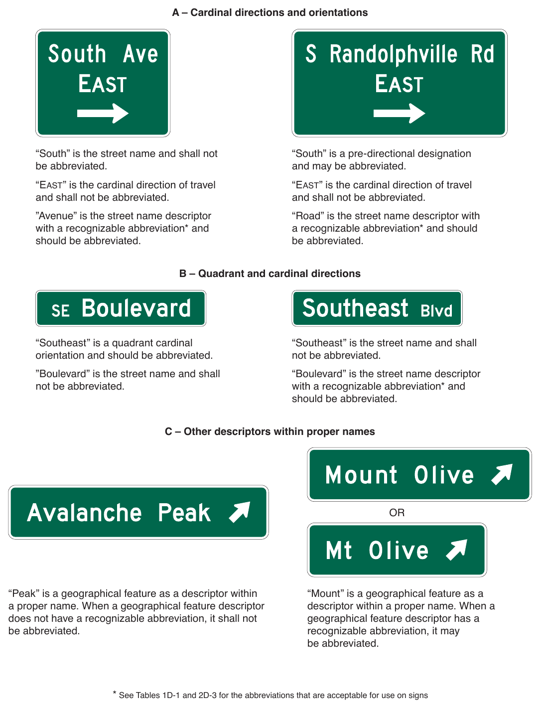
“South” is the street name and shall not be abbreviated. “South” is a pre-directional designation and may be abbreviated. “EAST” is the cardinal direction of travel and shall not be abbreviated. “EAST” is the cardinal direction of travel and shall not be abbreviated. ”Avenue” is the street name descriptor with a recognizable abbreviation and should be abbreviated. “Road” is the street name descriptor with a recognizable abbreviation and should be abbreviated. B – Quadrant and cardinal directions “Southeast” is a quadrant cardinal orientation and should be abbreviated. “Southeast” is the street name and shall not be abbreviated. ”Boulevard” is the street name and shall not be abbreviated. “Boulevard” is the street name descriptor with a recognizable abbreviation* and should be abbreviated. C – Other descriptors within proper names “Peak” is a geographical feature as a descriptor within a proper name. When a geographical feature descriptor does not have a recognizable abbreviation, it shall not be abbreviated. “Mount” is a geographical feature as a descriptor within a proper name. When a geographical feature descriptor has a recognizable abbreviation, it may be abbreviated.
§2D.08 Arrows¶
Table 2D-3. Acceptable Abbreviations for Street Name Descriptors
| Descriptor | Standard Abbreviation |
|---|---|
| Avenue | Ave |
| Boulevard | Blvd |
| Bypass | Byp |
| Causeway | Cswy |
| Circle | Cir |
| Corner | Cor |
| Court | Ct |
| Crescent | Cres |
| Drive | Dr |
| East | E* |
| Expressway | Expwy |
| Extension | Ext |
| Freeway | Fwy |
| Highway | Hwy |
| Lane | La, Ln |
| Landing | Lndg |
| North | N* |
| Northeast | NE* |
| Descriptor | Standard Abbreviation |
|---|---|
| Northwest | NW* |
| Parkway | Pkwy |
| Place | Pl |
| Plaza | Plz |
| Road | Rd |
| Route | Rte |
| South | S* |
| Southeast | SE* |
| Southwest | SW* |
| Square | Sq |
| Street | St |
| Terrace | Ter |
| Thruway | Thwy |
| Trafficway | Trfwy |
| Trail | Tr |
| Turnpike | Tpk |
| West | W* |
Support
01. Arrows are used for lane assignment and to indicate the direction toward designated routes or destinations. Figure 2D-3 shows the various standard arrow designs that have been approved for use on guide signs. Detailed drawings are shown for these arrows in the “Standard Highway Signs” publication (see Section 1A.05).
Standard
02. Except for Overhead Arrow-per-Lane signs (see Section 2D.37), on overhead signs where it is desirable to indicate a lane to be followed, a down arrow shall be positioned over the approximate center of the lane and shall point vertically downward toward the approximate center of that lane. Down arrows shall be used only on overhead guide signs that restrict the use of specific lanes to traffic bound for the destination(s) and/or route(s) indicated by these arrows. Down arrows shall not be used unless an arrow can be located over and pointed to the approximate center of each lane that can be used to reach the destination displayed on the sign.
03. If down arrows are used, having more than one down arrow pointing to the same lane on a single overhead sign (or on multiple signs on the same overhead sign structure) shall not be permitted.
04. Where a roadway is leaving the through lanes, a directional arrow shall point upward at an angle that approximates the alignment of the exit roadway in the vicinity of the point of departure.
05. The Type E directional arrow for circular intersections shall not be used on any sign that is not associated with a circular intersection.
Guidance
06. The Type A directional arrow should be used on guide signs on freeways, expressways, and conventional roads to indicate the direction to a specific destination or group of destinations, except as otherwise provided in this Section and in Section 2E.18.
Table 2D-4. Street Name Descriptors
| Descriptor | Descriptor |
|---|---|
| Alley | Oval |
| Belt | Pass |
| Beltway | Passage |
| Close | Path |
| Cove | Ridge |
| Edge | Row |
| Gate | Run |
| Green | Trace |
| Grove | Turn |
| Hill | View |
| Loop | Vista |
| Mews | Walk |
07. When a directional arrow in a vertical, upward-pointing orientation is placed to the side of a group of destinations to indicate a through movement, the Type A directional arrow should be used. When a directional arrow in a vertical, upward-pointing orientation is placed to the side of a single destination or under a destination or group of destinations, the Type B directional arrow should be used.
08. The Type B directional arrow should be used on guide signs on conventional roads when placed at any angle to the side of a single destination or when placed in a horizontal orientation to the side of a group of destinations.
09. The Type C advance turn directional arrow should be used on conventional road guide signs placed in advance of an intersection where a turn must be made to reach a posted destination or group of destinations.
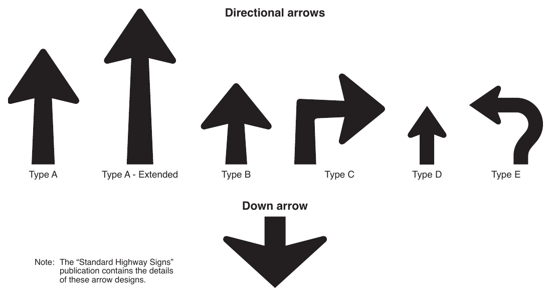
10. Note: The “Standard Highway Signs” publication contains the details of these arrow designs. The Type D directional arrow should be used primarily for sign applications other than guide signs, except as provided in Paragraph 15 of this Section.
11. If the Type E directional arrow is used, the principles set forth in Sections 2D.26 through 2D.29 should be followed.
Option
12. The Type A-Extended directional arrow may be used on guide signs where additional emphasis regarding the direction is needed relative to the amount of legend on the sign.
13. The Type C directional arrow may be used to the side of the legend of an overhead guide sign to accentuate a sharp turn exit maneuver from a mainline roadway (see Section 2E.25 for additional information regarding Exit Direction signs for low advisory ramp speeds).
14. On conventional roads on the approach to an intersection where the Combination Lane-Use/Destination overhead guide sign (see Section 2D.38) is not used, the Type C advance turn directional arrow may be used beneath the legend of an overhead guide sign to indicate the fact that a turn must be made from a mandatory movement lane over which the sign is placed to reach the destination or destinations displayed on the sign.
15. The Type D directional arrow may be used on post-mounted guide signs on conventional roads with lower operating speeds if the height of the text on the sign is 8 inches or less. Type D arrows may be used on a Street Name (D3-1 only) sign displaying two street names to indicate the different direction of travel for each street.
16. The Type E directional arrow may be used on guide signs on approaches to circular intersections to represent the intended driver paths to destinations involving left-turn movements around the central island.
17. The directional and down arrows shown in Figure 2D-3 may be used on signs other than guide signs for the purposes of providing directional guidance and lane assignment.
Guidance
18. Arrows used on guide signs to indicate the directions toward designated routes or destinations should be pointed at the appropriate angle to clearly convey the direction to be taken. A horizontally-oriented directional arrow design should be used at right-angle intersections.
19. On a post-mounted guide sign, a directional arrow for a straight-through movement should point upward. Except as provided in Section 2D.50, for a turn, the arrow on a guide sign should point horizontally or at an upward angle that approximates the sharpness of the turn.
20. At an exit, an arrow should be placed at the side of the sign that will reinforce the movement of exiting traffic. The directional arrow design should be used.
Standard
21. If used, the Type C advance turn directional arrow shall display a right or left arrow, the shaft of which is bent at a 90-degree or oblique angle.
Option
22. Arrows may be placed below the principal sign legend or on the appropriate side of the legend that is consistent with the direction of the movement.
23. On a post-mounted sign at an exit where placement of the arrow to the side of the legend farthest from the roadway would create an unusually wide sign that limits the road user’s view of the arrow, the directional arrow may be placed at the bottom portion of the sign, centered under the legend.
Guidance
24. The width across the arrowhead for the Types A, B, and C directional arrows should be between 1.5 and 1.75 times the height of the upper-case letters of the principal legend on the sign. The width across the arrowhead for the Type D directional arrow should be at least equal to the height of the upper-case letters of the principal legend on the sign. For down arrows used on overhead signs, the width across the arrowhead should be approximately 2 times the height of the upper-case letters of the principal legend on the sign.
Support
25. Section 2D.37 contains the provisions for arrows used in Overhead Arrow-per-Lane signs on approaches to conventional road intersections. Section 2E.41 contains the provisions for arrows used in Diagrammatic Advance guide signing on approaches to conventional road intersections other than circular intersections. Section 2D.39 contains the provisions for diagrammatic arrows used in Destination signs on the approaches to circular intersections (see Figure 2D-11).
26. The “Standard Highway Signs” publication (see Section 1A.05) contains design details and standardized sizes of the various arrows based on ranges of letter heights of principal legends.
ROUTE SIGNS AND AUXILIARY PLAQUES¶
§2D.09 Numbered Highway Systems¶
Support
01. The purpose of numbering and signing highway systems is to identify routes and facilitate travel.
02. The Interstate and United States (U.S.) highway systems are numbered by the American Association of State Highway and Transportation Officials (AASHTO) upon recommendations of the State highway organizations because the respective States own these systems. State and county road systems are numbered by the appropriate authorities.
03. The basic policy for numbering the Interstate and U.S. highway systems is contained in the following Purpose and Policy statements published by AASHTO:
- A. “Establishment and Development of United States Numbered Highways,” and
- B. “Establishment of a Marking System of the Routes Comprising the National System of Interstate and Defense Highways.”
Guidance
04. The principles of these policies should be followed in establishing the highway systems described in Paragraph 3 of this Section and any other systems, with effective coordination between adjacent jurisdictions. Care should be taken to avoid the use of numbers or other designations that have been assigned to Interstate, U.S., or State routes in the same geographic area. Overlapping numbered routes should be kept to a minimum.
Standard
05. Route systems shall be given preference in this order: Interstate, United States, State, and county. The preference shall be given by installing the highest-priority route number on the top or the left of the sign, except as provided in Paragraph 7 of this Section.
06. Interstate route numbering shall be approved by the FHWA.
Option
07. The prioritization of route systems may be modified when a different prioritization would better accommodate the expectancy of the road user and provide more effective direction, such as for separate decision points for routes that are encountered in a particular order.
Support
08. Section 2D.56 contains information regarding the signing of unnumbered highways to enhance route guidance and facilitate travel.
§2D.10 Route Signs and Auxiliary Plaques¶
Standard
01. Except as provided in Paragraph 9 of Section 2D.29, all numbered highway routes shall be identified by route signs and auxiliary plaques.
02. The signs for each system of numbered highways, which are distinctive in shape and color, shall be used only on that system and the approaches thereto.
Option
03. Route signs and auxiliary plaques may be proportionally enlarged where greater conspicuity or legibility is needed.
Support
04. Route signs are typically mounted in assemblies with auxiliary plaques.
05. Section 2D.57 contains information regarding the signing for National Scenic Byways.
06. Section 2D.58 contains information regarding the signing for State-designated scenic byways, historic trails, and auto tour routes.
§2D.11 Design of Route Signs¶
Standard
01. The design of standard route signs shall conform to the designs provided in the “Standard Highway Signs” publication (see Section 1A.05). The design of other route signs shall be established by the authority having jurisdiction and shall be in general conformance with the designs provided in the “Standard Highway Signs” publication.
02. Interstate Route (M1-1 and M1-1a) signs (see Figure 2D-4) shall be used on all Interstate routes and in connection with Route Sign assemblies on intersecting highways.
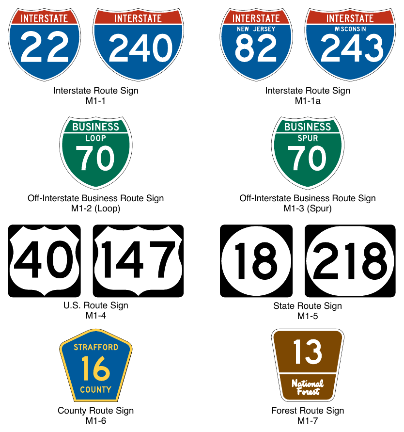
Signs shown: M1-1, M1-1a, M1-2, M1-3, M1-4, M1-5, M1-6, M1-7
03. M1-2 (Loop) Off-Interstate Business Route Sign M1-3 (Spur) U.S. Route Sign State Route Sign County Route Sign Forest Route Sign Except as otherwise provided in this Manual, a 24 x 24-inch minimum sign size shall be used for Interstate route numbers with one or two digits, and a 30 x 24-inch minimum sign size shall be used for Interstate route numbers having three digits.
Option
04. When the Interstate Route sign is used in a Route Sign assembly (see Section 2D.29), the M1-1a sign, containing the State name in white upper-case letters on a blue background as detailed in the “Standard Highway Signs” publication (see Section 1A.05), may be used in place of the M1-1 sign.
Standard
05. Use of the M1-1a sign shall be limited to Route Sign assemblies.
06. Off-Interstate Business Route (M1-2 and M1-3) signs (see Figure 2D-4) shall consist of a cutout shield displaying the number of the connecting Interstate route and the words BUSINESS and either LOOP (when the route rejoins the same Interstate route) or SPUR (when the route leaves the corresponding Interstate route and does not rejoin) in upper-case letters. The legend and border shall be white on a green background, and the shield shall be the same shape and dimensions as the Interstate Route sign. In no instance shall the word INTERSTATE appear on the Off-Interstate Business Route sign.
Option
07. The Off-Interstate Business Route sign may be used on a major highway that is not a part of the Interstate system, but one that serves the business area of a city from an interchange on the system.
Standard
08. U.S. Route signs (see Figure 2D-4) shall consist of black numerals on a white shield surrounded by a rectangular black background without a border. This sign shall be used on all U.S. routes and in connection with Route Sign assemblies on intersecting highways.
09. A 24 x 24-inch minimum sign size shall be used for U.S. route numbers with one or two digits, and a 30 x 24-inch minimum sign size shall be used for U.S. route numbers having three digits.
10. State Route signs shall be designed by the individual State highway agencies.
11. The legend on State Route signs shall conform to the Standard Alphabets contained in the “Standard Highway Signs” publication (see Section 1A.05).
Guidance
12. State Route signs (see Figure 2D-4) should be rectangular and should be approximately the same size as the U.S. Route sign. State Route signs should also be similar to the U.S. Route sign by containing approximately the same size black numerals on a white area surrounded by a rectangular black background without a border, and should be devoid of complex graphics. The shape of the white area should be circular in the absence of any determination to the contrary by the individual State concerned.
13. Where U.S. or State Route signs are used as components of guide signs, only the distinctive shape of the shield itself and the route numerals within should be used. The rectangular background upon which the distinctive shape of the shield is mounted, such as the black area around the outside of the shields on the M1-4 and standard M1-5 signs, should not be included on the guide sign. Where U.S. or State Route signs are used as components of other signs of non-contrasting background colors, the rectangular background should be used so that recognition of the distinctive shape of the shield can be maintained.
Standard
14. If county road authorities elect to establish and identify a special system of important county roads, a statewide policy for such signing shall be established that includes a uniform numbering system to uniquely identify each route. The County Route (M1-6) sign (see Figure 2D-4) shall consist of a pentagon shape with a yellow county name and route number and border on a blue background. County Route signs shall be a minimum size of 24 x 24 inches.
15. If a jurisdiction uses letters instead of numbers to identify routes, all references to numbered routes in this Chapter shall be interpreted to also include lettered routes.
Guidance
16. If used with other route signs in common assemblies, the County Route sign should be of a size compatible with that of the other route signs.
Option
17. When the County Route (M1-6) sign is used as a component of a guide sign, the county name and the legend COUNTY may be omitted from the County Route sign.
Standard
18. The design of the National Forest Route (M1-7) sign (see Figure 2D-4) shall be as detailed in the “Standard Highway Signs” publication (see Section 1A.05). Route signs for other park and forest roads shall be designed with an appropriate level of distinctiveness and adequate legibility, but in general compliance with the design principles for route signs and of a size compatible with other route signs used in common assemblies.
§2D.12 Design of Route Sign Auxiliary Plaques¶
Standard
01. Route sign auxiliary plaques displaying word legends, except the Junction (M2-1P) auxiliary plaque, shall have a minimum standard size of 24 x 12 inches. The Junction auxiliary plaque and those auxiliary plaques displaying arrows shall have a minimum standard size of 21 x 15 inches. All route sign auxiliary plaques shall match the color combination of the route sign that they supplement.
Guidance
02. The background, legend, and border of a route sign auxiliary plaque should have the same colors as those of the route sign with which the auxiliary plaque is mounted in a Route Sign assembly (see Section 2D.29). For a route sign design that uses multiple background colors, such as the Interstate Route sign, the background color of the corresponding auxiliary plaque should be that of the background area on which the route number is placed on the route sign.
Option
03. A route sign and any auxiliary plaques used with it may be combined on a single sign as a guide sign.
Standard
04. If a route sign and its auxiliary plaques are combined to form a single guide sign, the background color of the sign shall be green and the design shall comply with the basic principles for the design of guide signs. The auxiliary messages shall be white legends placed directly on the green background. Auxiliary plaques shall not be mounted directly to a guide sign or other type of sign.
Support
05. Chapter 2F contains information regarding auxiliary plaques for toll highways.
§2D.13 Junction Auxiliary Plaque (M2-1P)¶
Standard
The Junction (M2-1P) auxiliary plaque (see Figure 2D-5) shall display the abbreviated legend JCT and shall be mounted at the top of an assembly (see Section 2D.30) directly above the route sign, the sign for an alternative route (see Section 2D.17) that is part of the route designation, or the Cardinal Direction auxiliary plaque where access is available only to one direction of the intersected route. The minimum size of the Junction auxiliary plaque shall be 21 x 15 inches for compatibility with auxiliary plaques displaying arrow symbols.
§2D.14 Combination Junction Sign (M2-2)¶
Option
01. As an alternative to the standard Junction assembly where more than one route is to be intersected or joined, a rectangular guide sign may be used displaying the word JUNCTION above the route numbers.
Standard
02. The Combination Junction (M2-2) sign (see Figure 2D-5) shall have a green background with white border and lettering for the word JUNCTION.
Guidance
03. The Combination Junction sign should comply with the specific provisions of Section 2D.11 regarding the incorporation of the route signs as components of guide signs.
04. Although the size of the Combination Junction sign will depend on the number of routes involved, the numerals should be large enough for clear legibility and should be of a size comparable with those in the individual route signs.
§2D.15 Cardinal Direction Auxiliary Plaques (M3-1P through M3-4P)¶
Guidance
01. Cardinal Direction auxiliary plaques (see Figure 2D-5) displaying the legend NORTH, EAST, SOUTH, or WEST should be used to indicate the general direction of the entire route.
Standard
02. To improve the readability and recognition of the cardinal directions, the first letter of the cardinal direction words shall be ten percent larger, rounded up to the nearest whole number size.
03. If used, the Cardinal Direction auxiliary plaque shall be mounted directly above a route sign or, if used, an auxiliary plaque for an alternative route.
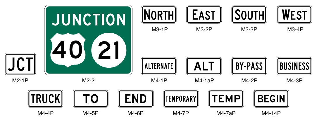
Signs shown: M3-1P, M3-2P, M3-3P, M3-4P, M2-1P, M2-2, M4-1P, M4-1aP, M4-2P, M4-3P, M4-4P, M4-5P, M4-6P, M4-7P, M4-7aP, M4-14P
§2D.16 Alternative Route Auxiliary Plaques (M4-1P through M4-4P)¶
Option
01. Alternative Route auxiliary plaques (see Figure 2D-5) displaying legends such as ALTERNATE, BY-PASS, BUSINESS, or TRUCK, may be used to indicate an alternate route of the same number between two points on that route.
Standard
02. If used, the Alternative Route auxiliary plaques shall be mounted directly above a route sign.
§2D.17 ALTERNATE Auxiliary Plaques (M4-1P and M4-1aP)¶
Option
01. The ALTERNATE (M4-1P) or the ALT (M4-1aP) auxiliary plaque (see Figure 2D-5) may be used to indicate an officially designated alternate routing of a numbered route between two points on that route.
Standard
02. If used, the ALTERNATE or ALT auxiliary plaque shall be mounted directly above a route sign.
03. The M4-1P series plaques shall not be used to sign an alternative routing that is not officially designated and incorporated into the numbered highway system, such as alternative routings for incident management or emergency detours.
Guidance
04. The shorter (time or distance) or better-constructed route should retain the regular route number, and the longer or worse-constructed route should be designated as the alternate route.
§2D.18 BY-PASS Auxiliary Plaque (M4-2P)¶
Option
01. The BY-PASS (M4-2P) auxiliary plaque (see Figure 2D-5) may be used to designate a route that branches from the numbered route through a city, bypasses a part of the city or congested area, and rejoins the numbered route beyond the city.
Standard
02. If used, the BY-PASS auxiliary plaque shall be mounted directly above a route sign.
§2D.19 BUSINESS Auxiliary Plaque (M4-3P)¶
Option
01. The BUSINESS (M4-3P) auxiliary plaque (see Figure 2D-5) may be used to designate an alternate route that branches from a numbered route, passes through the business portion of a city, and rejoins the numbered route beyond that area.
Standard
02. If used, the BUSINESS auxiliary plaque shall be mounted directly above a route sign.
§2D.20 TRUCK Auxiliary Plaque (M4-4P)¶
Option
01. The TRUCK (M4-4P) auxiliary plaque (see Figure 2D-5) may be used to designate an alternate route that branches from a numbered route, when it is desirable to encourage or require commercial vehicles to use the alternate route.
Standard
02. If used, the TRUCK auxiliary plaque shall be mounted directly above a route sign.
§2D.21 TO Auxiliary Plaque (M4-5P)¶
Option
01. The TO (M4-5P) auxiliary plaque (see Figure 2D-5) may be used to provide directional guidance to a particular road facility from other highways in the vicinity (see Section 2D.34).
Standard
02. If used, the TO auxiliary plaque shall be mounted directly above a route sign or an auxiliary plaque for an alternative route. If a Cardinal Direction auxiliary plaque is also included in the assembly, the TO auxiliary plaque shall be mounted directly above the Cardinal Direction auxiliary plaque.
§2D.22 END Auxiliary Plaque (M4-6P)¶
Guidance
01. The END (M4-6P) auxiliary plaque (see Figure 2D-5) should be used where the route being traveled ends, usually at a junction with another route.
Standard
02. If used, the END auxiliary plaque shall be mounted either directly above a route sign or above a sign for an alternative route that is part of the designation of the route being terminated.
§2D.23 BEGIN Auxiliary Plaque (M4-14P)¶
Option
01. The BEGIN (M4-14P) auxiliary plaque (see Figure 2D-5) may be used where a route begins, usually at a junction with another route.
Standard
02. If used, the BEGIN auxiliary plaque shall be mounted at the top of the first Confirming assembly (see Section 2D.33) for the route that is beginning.
Guidance
03. If a BEGIN auxiliary plaque is included in the first Confirming assembly, a Cardinal Direction auxiliary plaque should also be included in the assembly.
Standard
04. If a Cardinal Direction auxiliary plaque is also included in the assembly, the BEGIN auxiliary plaque shall be mounted directly above the Cardinal Direction auxiliary plaque.
§2D.24 TEMPORARY Auxiliary Plaques (M4-7P and M4-7aP)¶
Option
01. The TEMPORARY (M4-7P) or the TEMP (M4-7aP) auxiliary plaque (see Figure 2D-5) may be used for an interim period to designate a section of highway that is not planned as a permanent part of a numbered route, but that connects completed portions of that route.
Standard
02. If used, the TEMPORARY or TEMP auxiliary plaque shall be mounted directly above the route sign, above a Cardinal Direction auxiliary plaque, or above an auxiliary plaque for an alternate route that is a part of the route designation.
03. TEMPORARY or TEMP auxiliary plaques shall be promptly removed when the temporary route is abandoned.
§2D.25 Temporary Detour Signs and Auxiliary Plaques¶
Support
01. Chapter 6I contains information regarding Temporary Detour signs and auxiliary plaques.
§2D.26 Advance Turn Arrow Auxiliary Plaques (M5-1P, M5-2P, and M5-3P)¶
Standard
01. If used, the Advance Turn Arrow auxiliary plaque (see Figure 2D-6) shall be mounted directly below the route sign in Advance Route Turn assemblies, and shall display a right or left arrow, the shaft of which is bent at a 90-degree angle (M5-1P) or at an oblique angle (M5-2P).
02. If used, the Circular Intersection Advance Turn Arrow (M5-3P) auxiliary plaque (see Figure 2D-6) shall be used only on the approach to a circular intersection to depict a movement along the circulatory roadway around the central island and to the left, relative to the approach roadway and entry into the intersection.
Guidance
03. If the M5-3P plaque is used, then this arrow type should also be used consistently on any regulatory laneuse signs (see Chapter 2B), Destination signs (see Section 2D.36), and pavement markings (see Part 3) for a particular destination or movement.
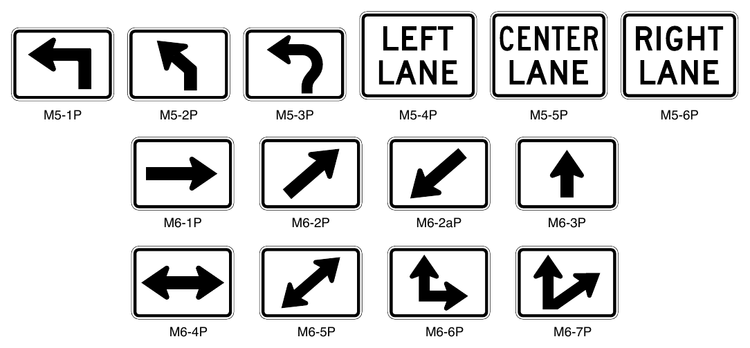
Signs shown: M5-1P, M5-2P, M5-3P, M5-4P, M5-5P, M5-6P, M6-1P, M6-2P, M6-2aP, M6-3P, M6-4P, M6-5P, M6-6P, M6-7P
§2D.27 Lane Designation Auxiliary Plaques (M5-4P, M5-5P, and M5-6P)¶
Option
01. A Lane Designation (M5-4P, M5-5P, or M5-6P) auxiliary plaque (see Figure 2D-6) may be mounted directly below the route sign in an Advance Route Turn assembly on multi-lane roadways to allow road users to move into the appropriate lane prior to reaching the intersection or interchange.
Standard
02. If used, the Lane Designation auxiliary plaques shall be used only where the designated lane is a mandatory movement lane and shall be located adjacent to the full-width portion of the mandatory movement lane. The Lane Designation auxiliary plaques shall not be installed adjacent to a through lane in advance of a lane that is being added or along the taper for a lane that is being added.
§2D.28 Directional Arrow Auxiliary Plaques (M6 Series)¶
Standard
01. If used, the Directional Arrow auxiliary plaque (see Figure 2D-6) shall be mounted below the route sign and any other auxiliary plaques in Directional assemblies (see Section 2D.32), and shall display a single-headed or double-headed arrow pointing in the general direction that the route follows.
02. A Directional Arrow auxiliary plaque that displays a double-headed arrow shall not be mounted in any Directional assembly in advance of or at a circular intersection.
Option
03. The diagonal downward-pointing arrow auxiliary (M6-2aP) plaque may be used in a Directional assembly at the far corner of an intersection to indicate the immediate entry point to a freeway or expressway entrance ramp (see Section 2D.50).
Standard
04. The M6-2aP plaque shall not be used on the approach to or on the near side of an intersection, such as to designate an approach lane.
SIGN ASSEMBLIES¶
§2D.29 Route Sign Assemblies¶
Standard
01. A Route Sign assembly shall consist of a route sign and auxiliary plaques that further identify the route and indicate the direction. Except as provided in Paragraph 9 of this Section, Route Sign assemblies shall be installed on all approaches to numbered routes that intersect with other numbered routes.
02. Where two or more routes follow the same section of highway, the route signs for Interstate, U.S., State, and county routes shall be mounted in that order from the left in horizontal arrangements and from the top in vertical arrangements. Subject to this order of precedence, route signs for lower-numbered routes shall be placed at the left or top.
03. Within groups of assemblies, information for routes intersecting from the left shall be mounted at the left in horizontal arrangements and at the top or center of vertical arrangements. Similarly, information for routes intersecting from the right shall be at the right or bottom, and for straight-through routes at the center in horizontal arrangements or top in vertical arrangements.
04. Route Sign assemblies shall be mounted in accordance with the general specifications for signs (Chapter 2A), with the lowest sign in the assembly at the height prescribed for single signs.
Guidance
05. Assemblies for two or more routes, or for different directions on the same route, should be mounted in groups on a common support.
06. Where more than four route signs would be needed in a single Advance Route Turn or Directional assembly, the route signs should instead be mounted in a guide sign to minimize the need for repetition of the same information on multiple Cardinal Direction and Directional Arrow auxiliary plaques (see Figure 2D-7).
Option
07. Route Sign assemblies may be installed on the approaches to numbered routes on unnumbered roads and streets that carry an appreciable amount of traffic destined for the numbered route.
08. If engineering judgment indicates that groups of assemblies that include overlapping routes or multiple turns might be confusing, route signs or auxiliary signs may be omitted or combined, provided that clear directions are given to road users.
09. Route Sign assemblies may be omitted for routes that are part of an agency’s internal numbering system, such as for maintenance or other purposes, and are not publicly mapped or intended to be used for navigational purposes by the general public. Similarly, numbered routes that are not maintained during certain times of year, such as not being plowed during winter months, may be omitted from Route Sign assemblies.
Support
10. Figure 2D-8 shows typical placements of route signs.
§2D.30 Junction Assembly¶
Standard
01. A Junction assembly shall consist of a Junction auxiliary plaque (see Section 2D.13) and a route sign. The route sign shall display the number of the intersected or joined route.
02. The Junction assembly shall be installed in advance of every intersection where a numbered route is intersected or joined by another numbered route.
Guidance
03. In urban areas, the Junction assembly should be installed in the block preceding the intersection. In urban areas where speeds are low, the Junction assembly should not be installed more than 300 feet in advance of the intersection.
04. In rural areas, the Junction assembly should be installed at least 400 feet in advance of the intersection. In rural areas, the minimum distance between a Junction assembly and either a Destination sign or an Advance Route Turn assembly should be 200 feet.
05. Where speeds are high, greater spacings should be used.
Option
06. Where two or more routes are to be indicated, a single Junction auxiliary plaque may be used for the assembly and all route signs grouped in a single mounting, or a Combination Junction (M2-2) sign (see Section 2D.14) may be used.
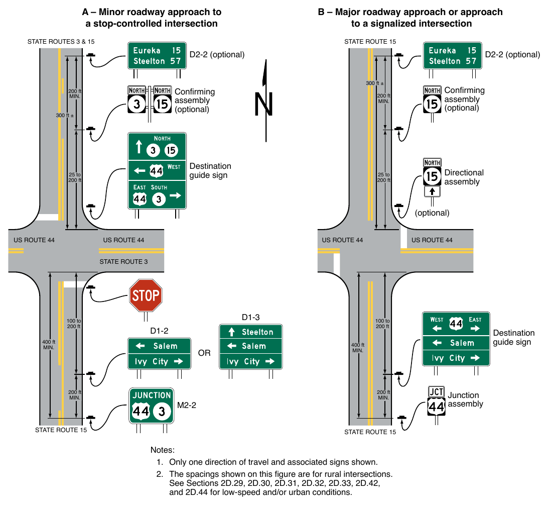
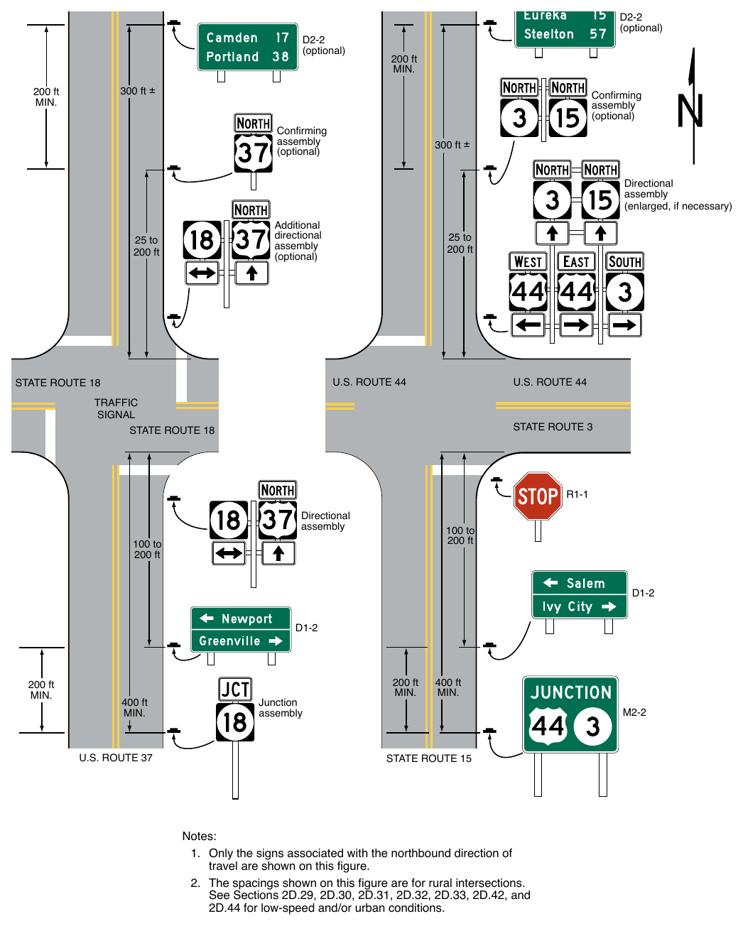
Assemblies into Guide Signs (Sheet 1 of 2) A – Minor roadway approach to a stop-controlled intersection B – Major roadway approach or approach to a signalized intersection STATE ROUTES 3 & 15 D2-2 (optional) D2-2 (optional) 300 ft ± Confirming assembly (optional) 200 ft 300 ft ± Destination guide sign 25 to 200 ft 200 ft Confirming assembly (optional) 25 to 200 ft Directional assembly (optional) 100 to 200 ft Notes:
- 1. Only one direction of travel and associated signs shown.
- 2. The spacings shown on this figure are for rural intersections. See Sections 2D.29, 2D.30, 2D.31, 2D.32, 2D.33, 2D.42, and 2D.44 for low-speed and/or urban conditions.
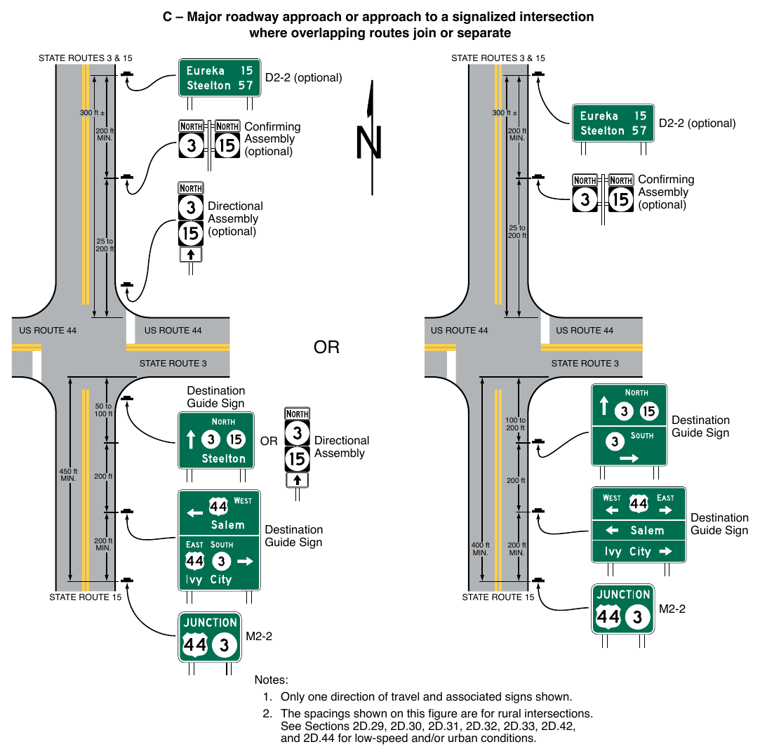
Assemblies into Guide Signs (Sheet 2 of 2) C – Major roadway approach or approach to a signalized intersection where overlapping routes join or separate STATE ROUTES 3 & 15 STATE ROUTES 3 & 15 D2-2 (optional) 300 ft ± Confirming Assembly (optional) 25 to 200 ft 50 to 100 ft 100 to 200 ft Directional Assembly 200 ft 200 ft Destination Guide Sign 450 ft D2-2 (optional) 200 ft Directional Assembly (optional) 25 to 200 ft 300 ft ± Confirming Assembly (optional) 200 ft Destination Guide Sign 200 ft Destination Guide Sign 400 ft Destination Guide Sign 200 ft Notes:
- 1. Only one direction of travel and associated signs shown.
- 2. The spacings shown on this figure are for rural intersections. See Sections 2D.29, 2D.30, 2D.31, 2D.32, 2D.33, 2D.42, and 2D.44 for low-speed and/or urban conditions.
(enlarged, if necessary) Additional directional assembly (optional) 25 to 200 ft 25 to 200 ft Directional assembly 100 to 200 ft 100 to 200 ft 200 ft 400 ft Junction assembly 200 ft 400 ft Notes:
- 1. Only the signs associated with the northbound direction of travel are shown on this figure.
- 2. The spacings shown on this figure are for rural intersections. See Sections 2D.29, 2D.30, 2D.31, 2D.32, 2D.33, 2D.42, and 2D.44 for low-speed and/or urban conditions.
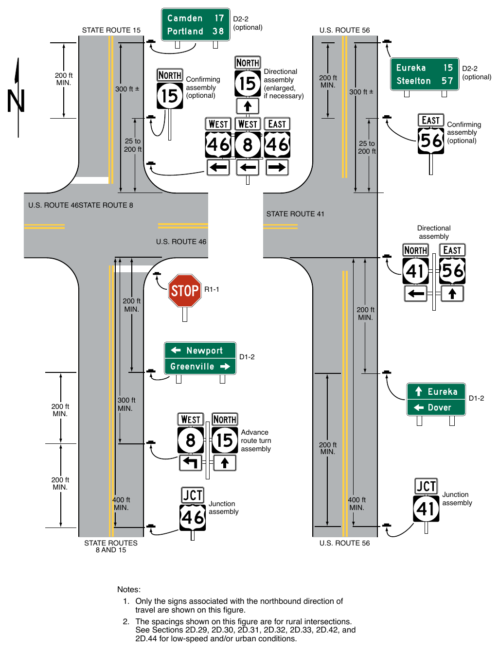
if necessary) Confirming assembly (optional) 200 ft (optional) 300 ft ± 25 to 200 ft 25 to 200 ft U.S. ROUTE 46STATE ROUTE 8 Confirming assembly (optional) Directional assembly 200 ft 200 ft 200 ft 300 ft Advance route turn assembly 200 ft 200 ft 400 ft Junction assembly 400 ft Junction assembly Notes:
- 1. Only the signs associated with the northbound direction of travel are shown on this figure.
- 2. The spacings shown on this figure are for rural intersections. See Sections 2D.29, 2D.30, 2D.31, 2D.32, 2D.33, 2D.42, and 2D.44 for low-speed and/or urban conditions.
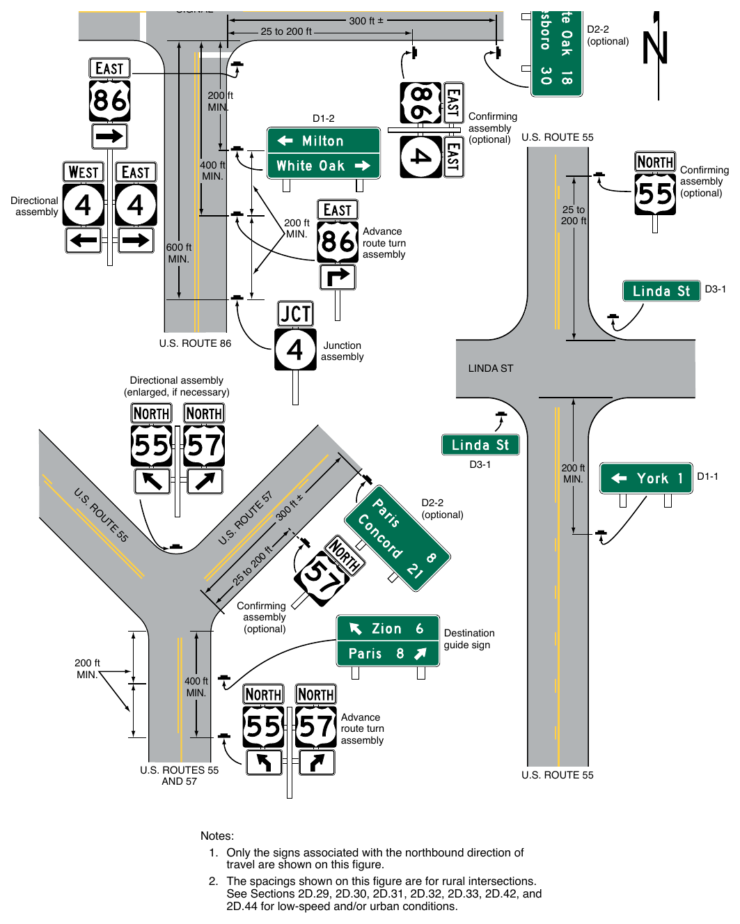
(optional) U.S. ROUTE 55 400 ft Confirming assembly (optional) Directional assembly 200 ft 600 ft 25 to 200 ft Advance route turn assembly Junction assembly Directional assembly (enlarged, if necessary)
25. D2-2 (optional) f to
20. ft Confirming assembly (optional) 200 ft
57. U
30. t± 200 ft Destination guide sign 400 ft Advance route turn assembly Notes:
- 1. Only the signs associated with the northbound direction of travel are shown on this figure.
- 2. The spacings shown on this figure are for rural intersections. See Sections 2D.29, 2D.30, 2D.31, 2D.32, 2D.33, 2D.42, and 2D.44 for low-speed and/or urban conditions.
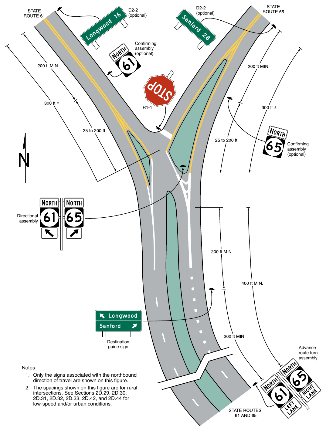
- 1. Only the signs associated with the northbound direction of travel are shown on this figure.
- 2. The spacings shown on this figure are for rural intersections. See Sections 2D.29, 2D.30, 2D.31, 2D.32, 2D.33, 2D.42, and 2D.44 for low-speed and/or urban conditions.
§2D.31 Advance Route Turn Assembly¶
Standard
01. An Advance Route Turn assembly shall consist of a route sign, an Advance Turn Arrow or word message auxiliary plaque, and a Cardinal Direction auxiliary plaque, if needed. It shall be installed in advance of an intersection where a turn must be made to remain on the indicated route.
Option
02. The Advance Route Turn assembly may be used to supplement the required Junction assembly in advance of intersecting routes.
Guidance
03. Where a multi-lane highway approaches an interchange or intersection with a numbered route, the Advance Route Turn assembly should be used to provide advance notice so that road users know the correct lane(s) from which to make their turn.
Option
04. Lane Designation auxiliary plaques (see Section 2D.27) may be used in Advance Route Turn Assemblies in place of the Advance Turn Arrow auxiliary plaques where engineering judgment indicates that specific lane information associated with each route is needed and overhead signing is impracticable and the designated lane is a mandatory movement lane. An assembly with the Lane Designation auxiliary plaques may supplement or substitute for an assembly with Advance Turn Arrow auxiliary plaques.
Guidance
05. In low-speed areas, the Advance Route Turn assembly should be installed not less than 200 feet in advance of the turn. In high-speed areas, the Advance Route Turn assembly should be installed not less than 300 feet in advance of the turn. In rural areas, the minimum distance between an Advance Route Turn assembly and either a Destination sign or a Junction assembly should be 200 feet.
Standard
06. An assembly that includes an Advance Turn Arrow auxiliary plaque shall not be placed where there is an intersection between it and the designated turn.
Guidance
07. Sufficient distance should be allowed between the assembly and any preceding intersection that could be mistaken for the indicated turn.
§2D.32 Directional Assembly¶
Standard
01. A Directional assembly shall consist of a Cardinal Direction auxiliary plaque, if needed; a route sign; and a Directional Arrow auxiliary plaque. The uses of Directional assemblies shall comply with the following:
- A. Turn movements (indicated in advance by an Advance Route Turn assembly) shall be marked by a Directional assembly with a route sign displaying the number of the turning route and a singleheaded arrow pointing in the direction of the turn.
- B. The beginning of a route (indicated in advance by a Junction assembly) shall be marked by a Directional assembly with a route sign displaying the number of that route and a single-headed arrow pointing in the direction of the route.
- C. An intersected route (indicated in advance by a Junction assembly) on a crossroad where the route is designated on both legs shall be designated by:
- 1. Two Directional assemblies, each with a route sign displaying the number of the intersected route, a Cardinal Direction auxiliary plaque, and a single-headed arrow pointing in the direction of movement on that route; or
- 2. A Directional assembly with a route sign displaying the number of the intersected route and a double-headed arrow, pointing at appropriate angles to the left, right, or ahead.
- D. An intersected route (indicated in advance by a Junction assembly) on a side road or on a crossroad where the route is designated only on one of the legs shall be designated by a Directional assembly with a route sign displaying the number of the intersected route, a Cardinal Direction auxiliary plaque, and a single-headed arrow pointing in the direction of movement on that route.
Guidance
02. Straight-through movements should be indicated by a Directional assembly with a route sign displaying the number of the continuing route and a vertical arrow. A Directional assembly should not be used for a straightthrough movement in the absence of other assemblies indicating right or left turns, as the Confirming assembly sign beyond the intersection normally provides adequate guidance.
03. Directional assemblies should be located on the near right corner of the intersection. At major intersections and at Y or offset intersections, additional Directional assemblies should be installed on the far right or left corner to confirm the near-side assemblies. When the near-corner position is impractical for Directional assemblies, the far right corner should be the preferred alternative, with oversized signs, if necessary, for legibility. Where unusual conditions exist, the location of a Directional assembly should be determined by engineering judgment with the goal being to provide the best possible combination of view and safety.
Support
04. It is more important that guide signs be readable, and that the information and direction displayed thereon be readily understood, at the appropriate time and place than to be located with absolute uniformity.
05. Figure 2D-8 shows typical placements of Directional assemblies.
§2D.33 Confirming or Reassurance Assemblies¶
Standard
01. If used, Confirming or Reassurance assemblies shall consist of a Cardinal Direction auxiliary plaque and a route sign. Where the Confirming or Reassurance assembly is for an alternative route, the appropriate auxiliary plaque for an alternative route (see Section 2D.16) shall also be included in the assembly.
Guidance
02. A Confirming assembly should be installed just beyond intersections of numbered routes. It should be placed 25 to 200 feet beyond the far shoulder or curb line of the intersected highway.
03. If used, Reassurance assemblies should be installed between intersections in urban areas as needed, and beyond the built-up area of any incorporated city or town.
04. Route signs for either confirming or reassurance purposes should be spaced at such intervals as necessary to keep road users informed of their routes.
§2D.34 Trailblazer Assembly¶
Support
01. Trailblazer assemblies provide directional guidance to a particular road facility from other highways in the vicinity. This guidance is accomplished by installing Trailblazer assemblies at strategic locations to indicate the direction to the nearest or most convenient point of access. The use of the word TO indicates that the road or street where the sign is posted is not a part of the indicated route, and that a road user is merely being directed progressively to the route.
Standard
02. A Trailblazer assembly shall consist of a TO auxiliary plaque (see Section 2D.21), a route sign for a numbered or named highway (see Section 2D.56) or an identification sign for a byway, historic trail, or auto tour route sign (see Sections 2D.57 and 2D.58), and a single-headed Directional Arrow auxiliary plaque pointing in the direction leading to the route. Where the Trailblazer assembly is for an alternative route, the appropriate auxiliary plaque for an alternative route (see Section 2D.16) shall also be included in the assembly.
Option
03. A Cardinal Direction auxiliary plaque (see Section 2D.15) may be used in a Trailblazer assembly where the direction leading to the route provides access only to one direction of travel for that route.
Guidance
04. The TO auxiliary plaque, Cardinal Direction auxiliary plaque, and Directional Arrow auxiliary plaque should be of the standard size provided for auxiliary plaques of their respective type. The route sign should be the size provided in Section 2D.11.
Option
05. Trailblazer assemblies may be installed with other Route Sign assemblies, or alone, in the immediate vicinity of the designated facilities.
DESTINATION AND DISTANCE SIGNS¶
§2D.35 Destination and Distance Signs¶
Support
01. In addition to guidance by route numbers, it is desirable to supply the road user information concerning the destinations that can be reached by way of numbered or unnumbered routes. This is done by means of Destination signs and Distance signs.
Option
02. Route shields and cardinal directions may be included on the Destination sign with the destinations and arrows.
Guidance
03. If Route shields and cardinal directions are included on a Destination sign, the height of the route shields should be at least two times the height of the upper-case letters of the principal legend and not less than 18 inches, and the letter height of cardinal directions should be at least the minimum letter height specified for these signs.
04. If used, destination names on low-volume rural roads should be as specific and descriptive as possible. Destinations such as campgrounds, ranger stations, and recreational areas should be clearly indicated so that they are not interpreted to be communities or locations with road user services.
§2D.36 Destination Signs (D1 Series)¶
Standard
01. Except on approaches to interchanges (see Section 2D.49), the Destination (D1-1 through D1-3) signs (see Figure 2D-9), if used, shall be a horizontal rectangle displaying the name of a city, town, village, or other traffic generator, and a directional arrow.
Option
02. The distance (see Section 2D.43) to the place named may also be displayed on the Destination (D1-1a through D1-3a) signs (see Figure 2D-9). If several destinations are to be displayed at a single point, the several names may be placed on a single sign with an arrow (and the distance, if desired) for each name. If more than one destination lies in the same direction, a single arrow may be used for such a group of destinations.
Guidance
03. Adequate separation should be made between any destinations or group of destinations in one direction and those in other directions by suitable design of the arrow, spacing of lines of legend, heavy lines entirely across the sign, or separate signs.
Support
04. Separation of destinations by direction by the use of a horizontal separator line can enhance the readability of a Destination sign by relating an arrow and its corresponding destination(s) and by eliminating the need for multiple arrows that point in the same direction and excessive space between lines of legend.
Standard
05. Except as otherwise provided in this Manual, an arrow pointing to the right shall be at the extreme right of the sign, and an arrow pointing left or up shall be at the extreme left. The distance numerals, if used, shall be placed to the right of the destination names.
Option
06. An arrow pointing up may be placed at the extreme right of the sign when the sign is mounted to the left of the traffic to which it applies.
Guidance
07. Unless a sloping arrow will convey a clearer indication of the direction to be followed, the directional arrows should be horizontal or vertical.
08. If several individual name signs are assembled into a group, all signs in the assembly should be of the same horizontal width.
09. Destination signs should be used:
- A. At the intersections of U.S. or State numbered routes with Interstate, U.S., or State numbered routes; and
- B. At points where they serve to direct traffic from U.S. or State numbered routes to the business section of towns, or to other destinations reached by unnumbered routes.
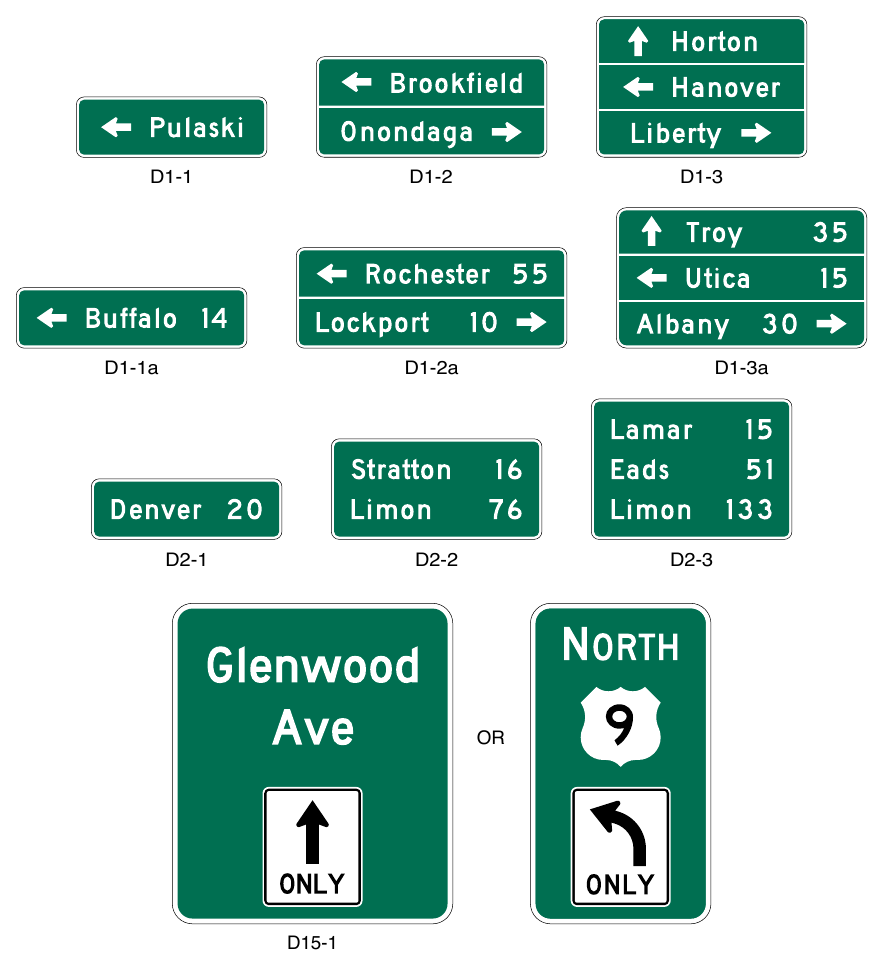
Signs shown: D1-1, D1-2, D1-3, D1-1a, D1-2a, D1-3a, D2-1, D2-2, D2-3, D15-1
Standard
10. Where a total of three or fewer destinations are displayed on the Advance guide (see Section 2E.23) and Supplemental guide (see Section 2E.51) signs, no more than three destination names shall be displayed on a Destination sign. Where four destinations are displayed on the Advance guide and Supplemental guide signs, no more than four destination names shall be displayed on a Destination sign.
Guidance
11. If space permits, four destinations should be displayed on two separate signs at two separate locations.
Option
12. Where space does not permit, or where all four destinations are in one direction, a single sign may be used. Where a single sign is used and all destinations are in the same direction, the arrow may be placed below the destinations for the purpose of enhancing the conspicuity of the arrow.
Standard
13. Where a single four-name sign assembly is used, a heavy line approximating the width of the sign border entirely across the sign or separate signs shall be used to separate destinations by direction.
Guidance
14. The closest destination lying straight ahead should be at the top of the sign or assembly, and below it the closest destinations to the left and to the right, in that order. The destination displayed for each direction should ordinarily be the next county seat or the next principal city, rather than a more distant destination. In the case of overlapping routes, only one destination should be displayed in each direction for each route.
Standard
15. If more than one destination is displayed in the same direction, the name of a nearer destination shall be displayed above the name of a destination that is farther away.
Support
16. Overhead destination guide signs are sometimes helpful on multi-lane conventional roadways with complex or unusual roadway alignments or geometrics at intersecting highways to provide positive direction to destinations and to assign lanes to be used for destinations.
Option
17. Overhead Destination signs may be used to provide lane assignment and destination information for some or all of the lanes on the approach to a multi-lane intersection. Destination information may include cardinal directions, route numbers, street names, and/or place names.
18. Overhead signs using the Arrow-per-Lane sign design configuration (see Figure 2D-10) may be used to provide lane assignments for some or all lane destinations at the approach to a multi-lane intersection (see Section 2D.37).
§2D.37 Overhead Arrow-per-Lane Destination Guide Signs¶
Support
01. Overhead Arrow-per-Lane destination guide signs are sometimes used on multi-lane conventional roadways to provide positive direction to destinations and to indicate lanes to be used for those destinations. These locations typically include complex or unusual roadway alignments or geometrics. Overhead Arrow-per-Lane signs on conventional roads do not always have arrows for every lane. Sheet 2 of Figure 2A-4 and Sheet 1 of Figure 2D-10 show examples of the use of an Overhead Arrow-per-Lane Guide sign on a conventional road. Unlike the Combined Lane-Use/Destination (D15-1) sign (see Section 2D.38), Overhead Arrow-per-Lane signs can be used to provide lane assignments where the designated lane is not a mandatory movement lane.
Option
02. At complex intersection approaches involving multiple lanes and destinations, an Overhead Arrow-per-Lane destination guide sign may be used to provide destination information for some or all lanes. Destination information may include cardinal direction, route numbers, street names, and/or place names.
Standard
03. Overhead Arrow-per-Lane signs for conventional roads shall only be used for multi-lane approaches to intersections that have an option lane.
04. Overhead Arrow-per-Lane guide signs used on conventional roads shall include as a minimum one arrow above each mandatory turn lane and a bifurcated arrow for the option lane from which both the through and turning movements are allowed.
Guidance
05. Displaying an arrow over each through movement lane that does not allow turning should be considered for providing additional positive guidance.
Standard
06. Overhead Arrow-per-Lane signs for conventional roads shall be designed in accordance with the following criteria:
- A. The shaft of each arrow shall be located over the approximate center of the lane to which it applies.
- B. Arrows for continuing through lanes shall be vertically upward-pointing (see Figure 2D-10).
- C. The arrow for a lane that must turn shall be curved in the direction of the turn and shall be accompanied by a black-on-yellow ONLY (E11-1b) sign panel (see Figure 2E-17) adjacent to the lower end of the arrow shaft.
- D. The arrow for an optional exit lane that also carries the through route shall have a single shaft that bifurcates into a vertically upward-pointing arrow and a curving arrow corresponding to the configuration of the through and turn lanes.
- E. A vertical white line shall be used to separate the route shields and destinations for the two diverging movements from each other.
- F. The number of lanes displayed on a sign shall correspond to the number of lanes being signed for at the location of that sign. An advance sign shall not depict lanes that are added downstream of a sign location.
Guidance
07. Overhead Arrow-per-Lane guide signs used on conventional roads should be designed in accordance with the following additional criteria:
- A. No more than one destination should be displayed for each movement, and no more than three destinations should be displayed per sign.
- B. The arrowhead(s) for the diverging movement should be positioned lower on the sign than the arrowhead(s) for the movement that continues straight ahead.
- C. Route shields, cardinal directions, and destinations should be positioned on the sign such that they are clearly related to the arrowhead(s) for the movement to which they apply.
- D. The vertical white line that is used to separate the route shields and destinations for the two diverging movements from each other should not descend below the top of the arrowheads for the through lanes, and should be positioned approximately halfway between the diverging arrowheads for the optional movement lane.
08. Destination information should be kept to a minimum necessary to provide positive guidance without overloading the road user.
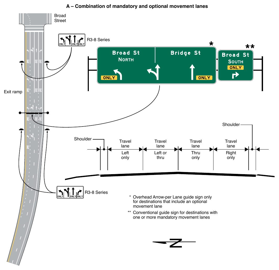
Signs shown: R3-8
Standard
09. The minimum height of arrows on an Overhead Arrow-per-Lane sign used on a conventional road shall be as shown in Table 2D-5.
Guidance
10. When letter heights and other sign legend elements are enlarged there should be a corresponding increase in the arrow size used.
Option
11. Curved-stem arrows may be substituted on Overhead Arrow-per-Lane signs on multi-lane approaches to a circular intersection with an option lane (see Section 2D.39).
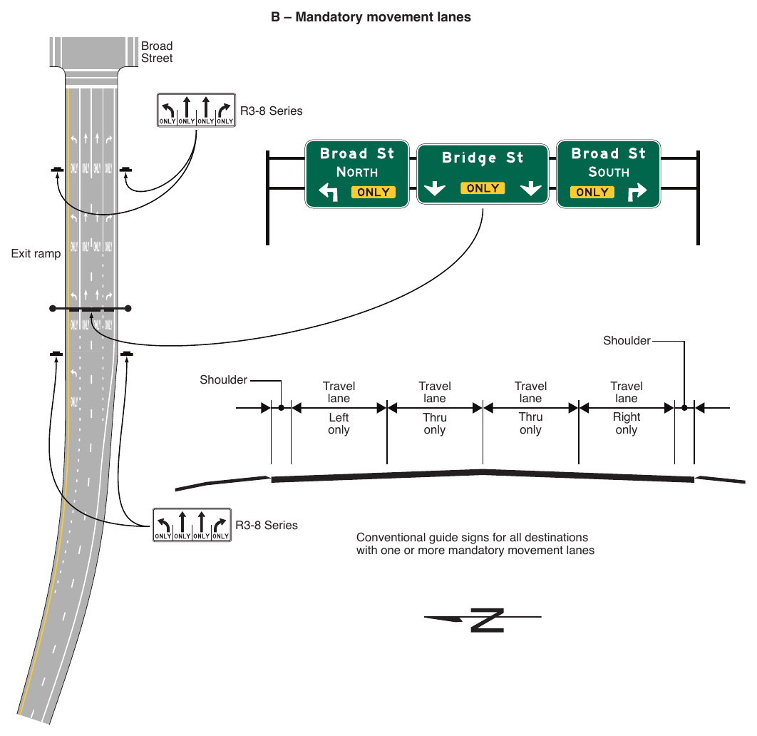
Signs shown: R3-8
Table 2D-5. Overhead Arrow-per-Lane Arrow Height Based on Principal Legend Letter Height
| Principal Legend Letter Height | Straight Arrow | Turn Arrow |
|---|---|---|
| 13.33 | 32 | 25.333 |
| 10.67 | 25.5 | 20.188 |
| 8 | 21 | 16.625 |
Note: Letter and arrow heights are shown in inches.
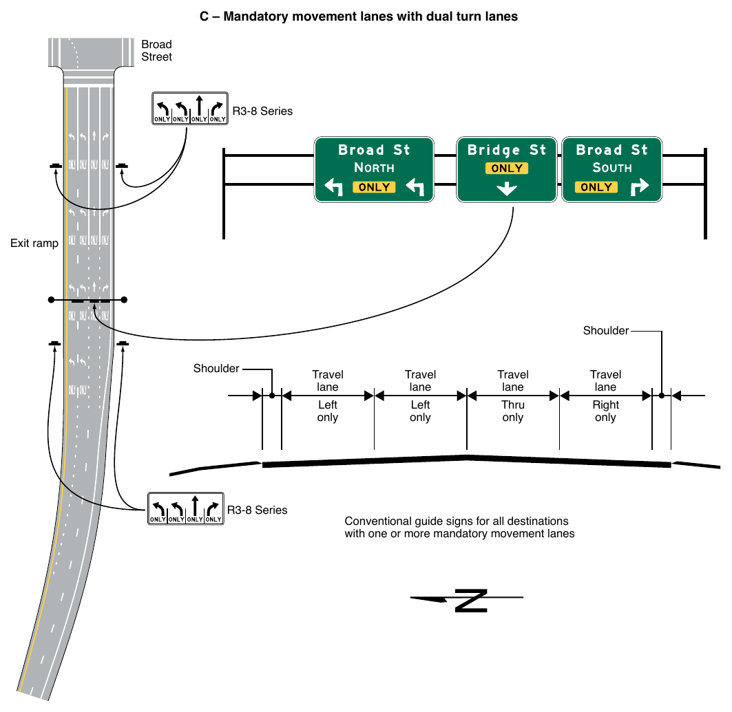
§2D.38 Combination Lane-Use/Destination Overhead Guide Sign (D15-1)¶
Option
01. At intersection approaches involving multiple turn lanes and destinations, a Combination Lane-Use/ Destination (D15-1) overhead guide sign (see Figure 2D-9) that combines a lane-use regulatory sign with destination information such as a cardinal direction, a route number, a street name, and/or a place name may be used.
Support
02. At such locations, the combined information on the D15-1 signs can be even more effective than separate laneuse and guide signs for conveying to unfamiliar drivers which lane or lanes to use for a particular destination.
03. Figure 2D-9 shows an example of a D15-1 sign that combines lane-use and street name information and an example of a D15-1 sign that combines lane-use, cardinal direction, and route number information.
Standard
04. The Combination Lane-Use/Destination (D15-1) overhead guide sign shall be used only where the designated lane is a mandatory movement lane. The D15-1 sign shall not be used for lanes with optional movements.
05. The D15-1 sign shall have a green background with a white border. As shown in Figure 2D-9, the laneuse sign (see Chapter 2B) shall be placed near the bottom of the sign and the destination information shall be placed near the top of the sign. The D15-1 sign shall be located over the approximate center of the lane to which it applies.
§2D.39 Destination Signs at Circular Intersections¶
Standard
01. Destination signs that are used at circular intersections shall comply with the provisions of Section 2D.36, except as provided in this Section.
Option
02. Exit Destination (D1-1d and D1-1e) signs (see Figure 2D-11) with diagonal upward-pointing arrows or Directional assemblies (see Section 2D.32) may be used to designate a particular exit from a circular intersection.
03. Destination (D1-2d and D1-3d) signs (see Figure 2D-11) with curved-stem arrows may be used on approaches to circular intersections to represent the left-turn movements.
04. Curved-stem arrows on circular intersection destination signs may point in diagonal directions to depict the location of an exit relative to the approach roadway and entry into the intersection.
05. An Overhead Arrow-per-Lane Destination sign (see Section 2D.37) with curved-stem arrows may be used on multi-lane approaches to circular intersections that have an option lane.
06. A Destination (D1-5 or D1-5a) sign (see Figure 2D-11) with a diagram of the circular intersection may be used on approaches to circular intersections.
Guidance
07. If curved-stem arrows are used on destination signs, then this arrow type should also be used consistently on any regulatory lane-use signs (see Chapter 2B), Directional assemblies (see Section 2D.32), and pavement markings (see Part 3) for a particular destination or movement.
Support
08. Figure 2D-12 shows examples of guide signing for circular intersections.
09. Circular Intersection Diagrammatic (D1-5 or D1-5a) signs might be preferable where space is available and where the geometry of the circular intersection is non-typical, such as where more than four legs are present or where the legs are not at approximately 90-degree angles to each other. In such cases, minimizing the amount of legend for each destination and designing the sign so that the arrows for each destination clearly align with the roadway geometry will aid road user understanding of the sign and navigation through the area.
Standard
10. If used, the Circular Intersection Diagrammatic signs shall not depict the number of lanes within the circulatory roadway of the intersection, or on its approaches or exits, through the use of lane lines, multiple arrow shafts for the same movement, or other methods.
Support
11. Chapter 2B contains information regarding regulatory signs at circular intersections, Chapter 2C contains information regarding warning signs at circular intersections, and Chapter 3D contains information regarding pavement markings at circular intersections.
§2D.40 Destination Signs at Jughandles¶
Standard
01. Destination signs that are used at jughandles shall comply with the provisions of Section 2D.36.
Support
02. Section 2B.35 contains information regarding regulatory signs for jughandle turns. Figure 2B-9 shows examples of regulatory and destination guide signing for various types of jughandle turns.
§2D.41 Destination Signs at Intersections with Indirect Turning Movements¶
Guidance
01. A system of guide signs along with associated lane markings should be used to direct traffic through intersections with indirect turning movements.
Support
02. Figure 2D-13 shows examples of destination guide signing for intersections with indirect turning movements.
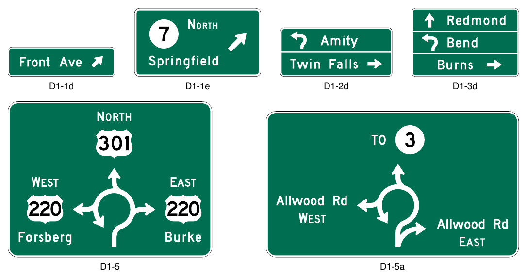
§2D.42 Location of Destination Signs¶
Guidance
01. When used in high-speed areas, Destination signs should be located 200 feet or more in advance of the intersection, and following any Junction or Advance Route Turn assemblies that might be required. In rural areas, the minimum distance between a Destination sign and either an Advance Route Turn assembly or a Junction assembly should be 200 feet.
Option
02. In urban areas, advance distances shorter than those specified in Paragraph 1 of this Section may be used.
03. Because the Destination sign is of lesser importance than the Junction, Advance Route Turn, or Directional assemblies, the Destination sign may be eliminated where the distance in which to provide adequate sign spacing is limited.
Support
04. Figure 2D-8 shows typical placements of Destination signs.
§2D.43 Distance Signs (D2 Series)¶
Standard
01. If used, the Distance (D2-1 through D2-3) signs (see Figure 2D-9) shall be a horizontal rectangle of a size appropriate for the required legend, displaying the names of no more than three cities, towns, junctions, or other traffic generators, and the distance (to the nearest mile) to those places.
02. The distance numerals shall be placed to the right of the destination names as shown in Figure 2D-9.
Guidance
03. The distance displayed should be selected on a case-by-case basis by the jurisdiction that owns the road or by statewide policy. A well-defined central area or central business district should be used where one exists. In other cases, the layout of the community should be considered in relation to the highway being signed and the decision based on where it appears that most drivers would feel that they are in the center of the community in question.
04. The top name on the Distance sign should be that of the next place on the route having a post office or a railroad station, a route number or name of an intersected highway, or any other significant geographical identity. The bottom name on the sign should be that of the next major destination or control city. If three destinations are displayed, the middle line should be used to indicate communities of general interest along the route or important route junctions.
Option
05. The choice of names for the middle line may be varied on successive Distance signs to give road users additional information concerning communities served by the route.
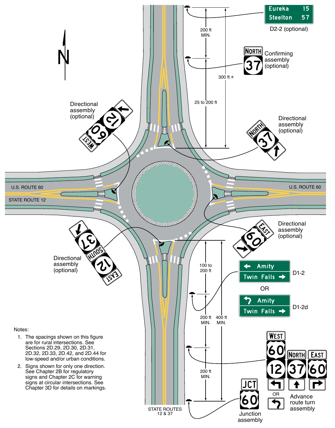
D2-2 (optional) 200 ft Confirming assembly (optional) 300 ft ± 25 to 200 ft Directional assembly (optional) Directional assembly (optional) Directional assembly (optional) Directional assembly (optional) 100 to 200 ft D1-2d 200 ft 400 ft Notes:
- 1. The spacings shown on this figure are for rural intersections. See Sections 2D.29, 2D.30, 2D.31, 2D.32, 2D.33, 2D.42, and 2D.44 for low-speed and/or urban conditions.
- 2. Signs shown for only one direction. See Chapter 2B for regulatory signs and Chapter 2C for warning signs at circular intersections. See Chapter 3D for details on markings. 200 ft MIN. OR STATE ROUTES 12 & 37 Junction assembly Advance route turn assembly
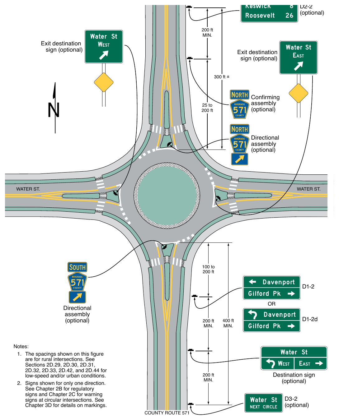
sign (optional) Exit destination sign (optional) 300 ft ± Confirming assembly (optional) 25 to 200 ft Directional assembly (optional) 100 to 200 ft Directional assembly (optional) Notes:
- 1. The spacings shown on this figure are for rural intersections. See Sections 2D.29, 2D.30, 2D.31, 2D.32, 2D.33, 2D.42, and 2D.44 for low-speed and/or urban conditions.
- 2. Signs shown for only one direction. See Chapter 2B for regulatory signs and Chapter 2C for warning signs at circular intersections. See Chapter 3D for details on markings. 200 ft MIN. 200 ft MIN. COUNTY ROUTE 571 400 ft MIN. D1-2d Destination sign (optional) D3-2 (optional)
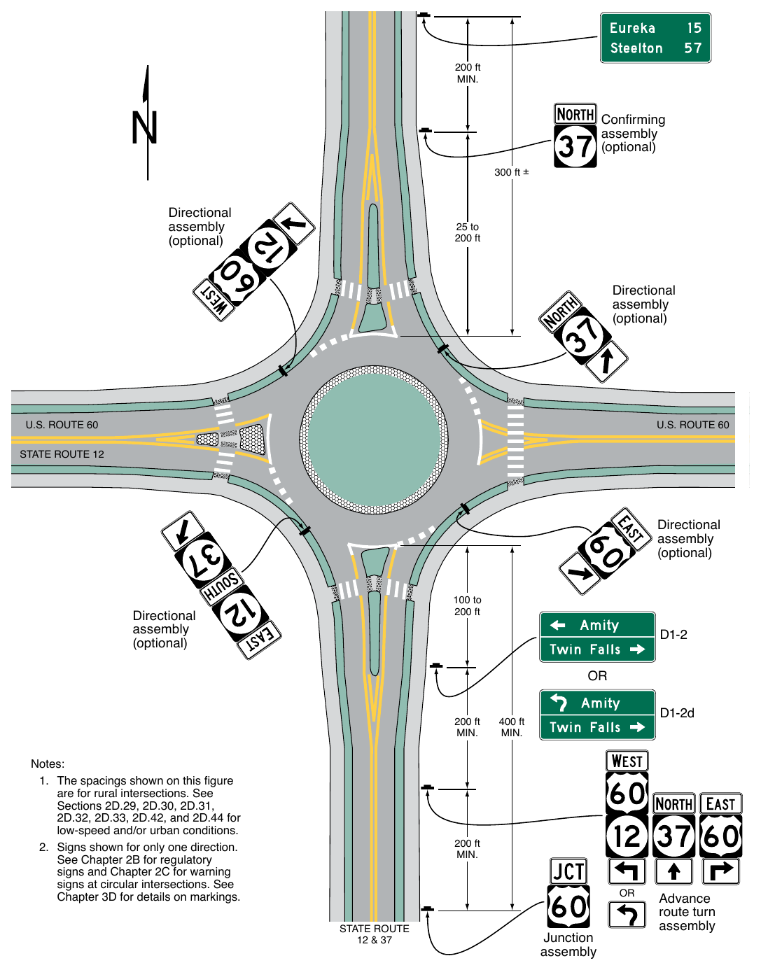
- 1. The spacings shown on this figure are for rural intersections. See Sections 2D.29, 2D.30, 2D.31, 2D.32, 2D.33, 2D.42, and 2D.44 for low-speed and/or urban conditions.
- 2. Signs shown for only one direction. See Chapter 2B for regulatory signs and Chapter 2C for warning signs at circular intersections. See Chapter 3D for details on markings. 200 ft MIN. OR STATE ROUTE 12 & 37 D1-2d 400 ft MIN. Junction assembly Advance route turn assembly
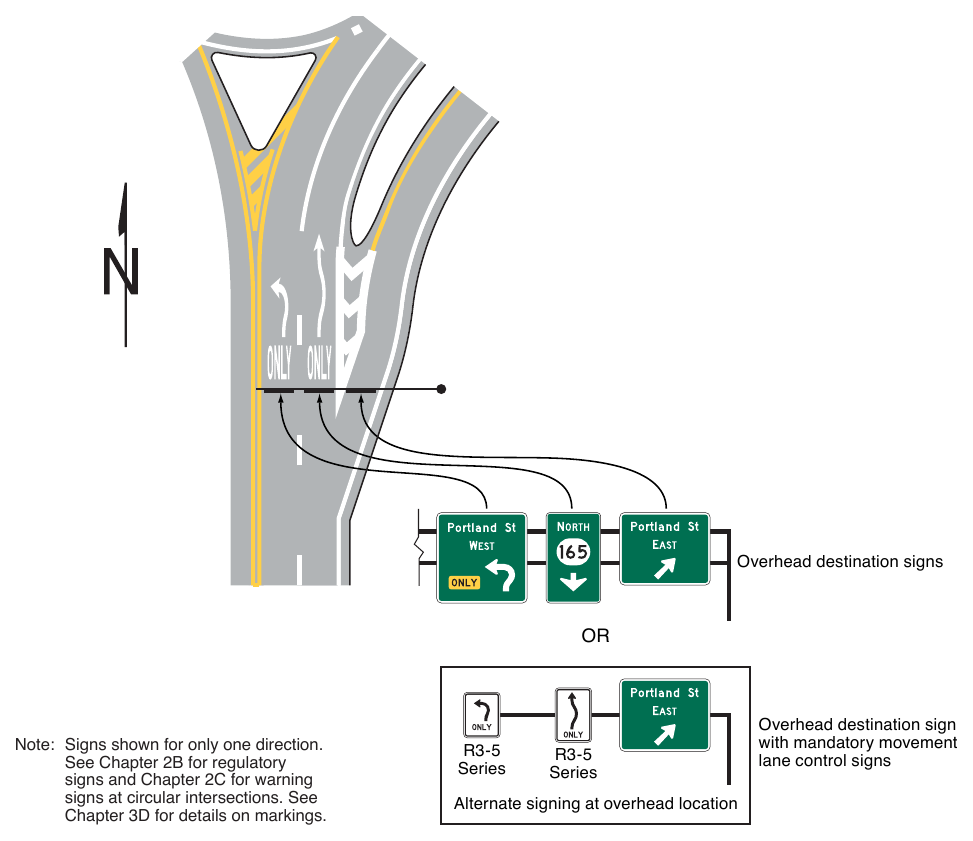
Note: Signs shown for only one direction. See Chapter 2B for regulatory signs and Chapter 2C for warning signs at circular intersections. See Chapter 3D for details on markings.
Guidance
06. The control city should remain the same on all successive Distance signs throughout the length of the route until that city is reached.
Option
07. If more than one distant point may properly be designated, such as where the route divides at some distance ahead to serve two destinations of similar importance, and if these two destinations cannot appear on the same sign, the two names may be alternated on successive signs.
08. On a route continuing into another State, destinations in the adjacent State may be displayed.
§2D.44 Location of Distance Signs¶
Guidance
01. If used, Distance signs should be installed on important routes leaving municipalities and just beyond intersections of numbered routes in rural areas. If used, they should be placed just outside the municipal limits or at the edge of the built-up area if it extends beyond the limits.
02. Where overlapping routes separate a short distance from the municipal limits, the Distance sign at the municipal limits should be omitted. The Distance sign should be installed approximately 300 feet beyond the separation of the two routes.
03. Where, just outside of an incorporated municipality, two routes are concurrent and continue concurrently to the next incorporated municipality, the top name on the Distance sign should be that of the place where the routes separate; the bottom name should be that of the city to which the greater part of the through traffic is destined.
Support
04. Figures 2D-7 and 2D-8 show typical placements of Distance signs.
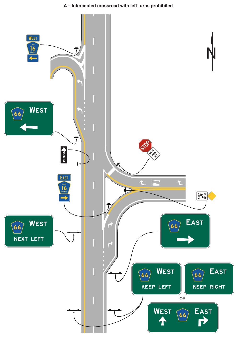
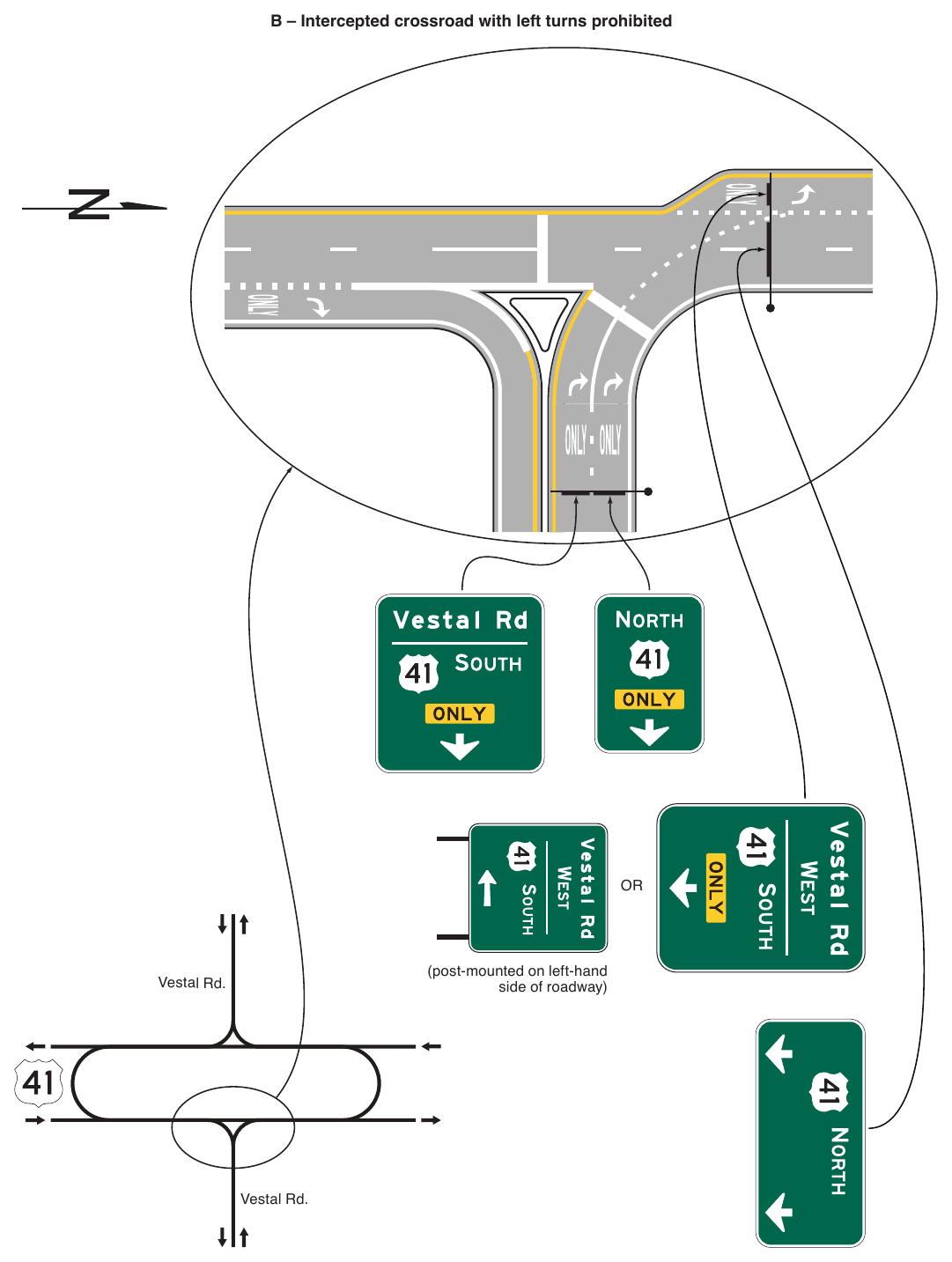
(post-mounted on left-hand side of roadway) Vestal Rd. Vestal Rd.
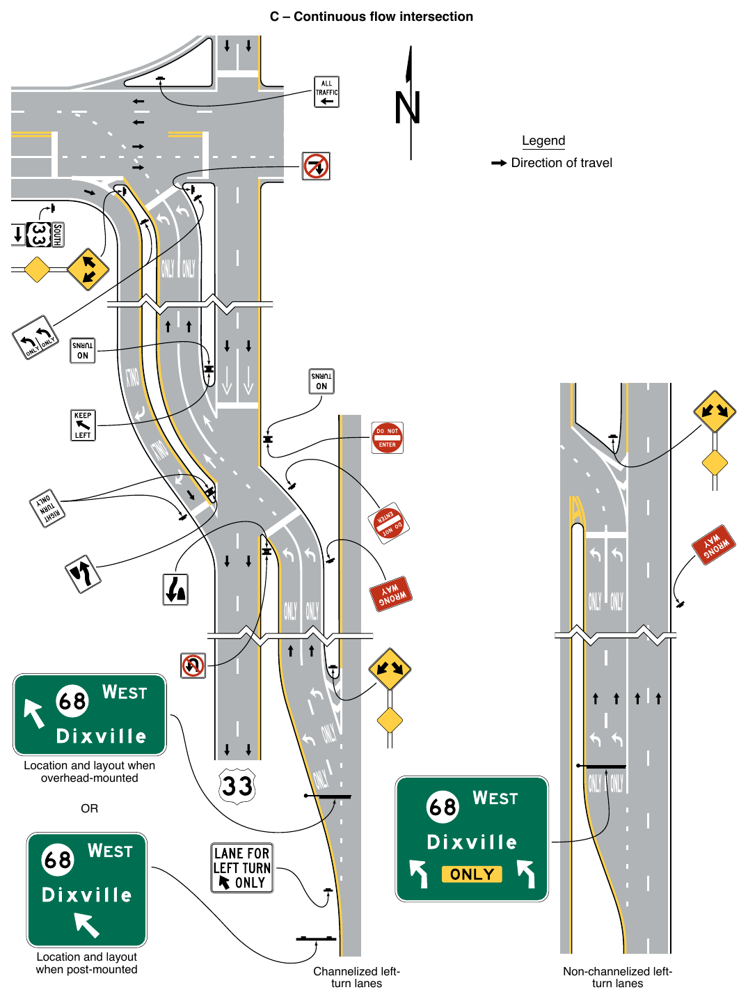
STREET NAME AND PARKING SIGNS¶
§2D.45 Street Name Signs (D3-1 and D3-1a)¶
Support
01. Street Name signs at intersections and along roadways provide road users with important navigation information. Section 2H.10 contains information about signs used to identify the names of grade-separated streets, railways, bikeways, or other transportation facilities.
Guidance
02. Street Name (D3-1 or D3-1a) signs (see Figure 2D-14) should be installed in urban areas at all street intersections regardless of other route signs that might be present and should be installed in rural areas to identify important roads that are not otherwise signed.
03. To minimize wrong-way movements onto freeway or expressway exit ramps, Street Name signs should not be used at the intersection of a freeway or expressway exit ramp with the crossroad to display the name of the freeway or expressway to traffic on the crossroad.
Option
04. For streets that are part of a U.S., State, or county numbered route, a D3-1a Street Name sign (see Figure 2D-14) that incorporates a route shield may be used to assist road users who might not otherwise be able to associate the name of the street with the route number.
Standard
05. The lettering for names of streets and highways on Street Name signs shall be composed of a combination of lower-case letters with initial upper-case letters (see Section 2A.08).
Guidance
06. The determination of letter heights to be used on Street Name signs should be based on, but not limited to, the following considerations:
- A. Use of Advance Street Name signs (see Section 2D.46);
- B. Number of lanes on the intersection approach;
- C. Length of turn lanes;
- D. Distance the Street Name sign is located across the intersection (if a sign is not provided on the near side of the intersection).
07. Letter heights on street name signs should be as shown in Table 2D-6.
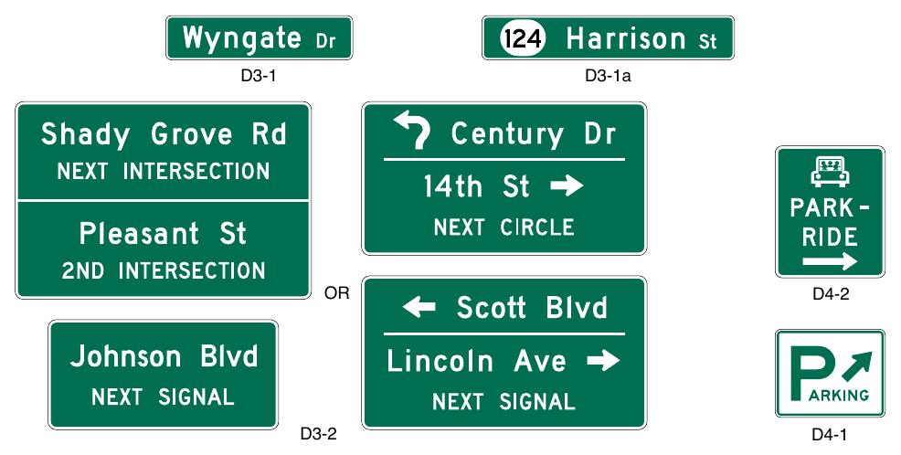
Table 2D-6. Minimum Letter Heights on Street Name Signs
| Type of Mounting | Type of Street or Highway | Speed Limit | Recommended Minimum Letter Height * | |
|---|---|---|---|---|
| Initial Upper-Case | Lower-Case | |||
| Overhead | All types | All speed limits | 12 inches | 9 inches |
| Post-mounted | Multi-lane | More than 40 mph | 8 inches | 6 inches |
| Post-mounted | Multi-lane | 40 mph or less | 6 inches | 4.5 inches |
| Post-mounted | 2-lane | All speed limits | 6 inches** | 4.5 inches** |
* Letter heights shown are for the street name. Descriptors or other supplementary legend may be displayed in smaller lettering of at least 3 inches.
** On two-lane local streets with speed limits of 25 mph or less, 4-inch initial upper-case letters with 3-inch lower-case letters may be used.
Option
08. For two-lane local roadways with speed limits of 25 mph or less, the lettering on post-mounted Street Name signs may be composed of initial upper-case letters at least 4 inches in height and lower-case letters at least 3 inches in nominal loop height.
Support
09. The recommended minimum letter heights for Street Name signs are summarized in Table 2D-6. The speed limits specified and the recommended minimum letter heights provided in this Section apply to the roadway that each Street Name sign faces rather than to the street that has its name displayed on the Street Name sign. The letter heights specified in Table 2D-6 are the combination of lower-case letters with the initial upper-case letter of a mixed-case legend.
10. A minimum upper-case letter height of 12 inches with a lower-case nominal loop height of 9 inches is recommended for all overhead Street Name signs regardless of posted speed limit as Street Name signs generally require greater legibility distances for road users to properly react.
Option
11. Each Street Name sign in a sign assembly may use different letter heights determined by the speed limit of the street that each sign faces.
12. The letter height of the street name descriptor (such as St, Ave, or Rd), the directional legend (such as NW), or any other supplemental legend (such as block or house numbers) on the D3-1 and D3-1a signs may be smaller than that of the street name itself.
Guidance
13. The letter height of the street name descriptor, the directional legend, or any other supplemental legend on the D3-1 and D3-1a signs should be at least two-thirds of the letter height of the street name itself, but not less than 3 inches for the initial upper-case letters and not less than 2.25 inches for the nominal loop height of the lower-case letters.
14. Conventional abbreviations (see Section 1D.08) should be used except for the street name itself. Acceptable abbreviations for street name descriptors such as “Ave” for Avenue and “Blvd” for Boulevard should be as provided in Table 2D-3 (see Section 2D.07). The street name descriptors that are provided in Table 2D-4 should not be abbreviated (see Section 2D.07).
Option
15. Block or house numbers may be displayed as a supplemental legend on a Street Name sign to aid emergency responders and road users in locating addresses.
Guidance
16. If block or house numbers are displayed on a Street Name sign where only a single Street Name sign is provided for the crossroad, the block or house numbers for the left and right blocks should be positioned at the left and right sides of the sign, respectively.
17. If block or house numbers are displayed on a Street Name sign where two Street Name signs are provided for the crossroad, such as on diagonally opposite corners of an intersection, each Street Name sign should display only the block or house numbers associated with that block of the crossroad.
Option
18. A pictograph (see definition in Section 1C.02) representing the municipality, in accordance with the provisions of Section 2A.04, may be used on a D3-1 sign. For street networks under the primary jurisdiction of another governmental-approved entity, such as within a college or university campus, within a military base, or within a transportation facility (such as an airport or port), a pictograph representing that entity, in accordance with the provisions of Section 2A.04, may be used on a D3-1 sign within the jurisdictional boundaries of that entity.
Standard
19. Pictographs shall not be displayed on D3-1a or Advance Street Name (D3-2) signs (see Section 2D.46).
20. If a pictograph is used on a D3-1 sign, the height and width of the pictograph shall not exceed the uppercase letter height of the principal legend of the sign.
Guidance
21. The pictograph should be positioned to the left of the street name.
22. Pictographs should not be used on a D3-1 sign that contains directional arrows.
Standard
23. The Street Name sign shall be retroreflective or illuminated in accordance with the provisions of Section 2A.21.
Option
24. The border may be omitted from a post-mounted Street Name sign.
Guidance
25. The decision to omit the border from a post-mounted Street Name sign should be based on such factors as the visual complexity of the environment and the degree of conspicuity needed to provide for adequate recognition of the sign by the road user.
Option
26. An alternative background color (see Paragraph 28 of this Section) other than the standard guide sign color of green may be used for Street Name (D3-1 or D3-1a) signs where the highway agency determines this is necessary to assist road users in determining jurisdictional authority for roads.
Standard
27. Alternative background colors shall not be used for Advance Street Name (D3-2) signs (see Section 2D.46).
28. The only acceptable alternative background colors for Street Name (D3-1 or D3-1a) signs shall be blue, brown, or white. Regardless of whether green, blue, or brown is used as the background color for Street Name (D3-1 or D3-1a) signs, the legend (and border, if used) shall be white. For Street Name signs that use a white background, the legend (and border, if used) shall be black.
Guidance
29. An alternative background color for Street Name signs, if used, should be applied to the Street Name (D3-1 or D3-1a) signs on all roadways under the jurisdiction of a particular highway agency.
30. In business or commercial areas and on principal arterials, Street Name signs should be placed at least on diagonally opposite corners. In residential areas, at least one Street Name sign should be mounted at each intersection. Signs naming both streets should be installed at each intersection. They should be mounted with their faces parallel to the streets they name.
31. Where used, Street Name signs should display their legends on both the front and back sides of the sign to facilitate navigation for pedestrians.
Option
32. To optimize visibility, Street Name signs may be mounted overhead. Street Name signs may also be placed above a regulatory or STOP or YIELD sign with no required vertical separation.
Guidance
33. In urban or suburban areas, especially where Advance Street Name signs for signalized and other major intersections are not used, the use of overhead Street Name signs should be strongly considered.
Option
34. At intersection crossroads where the same road has two different street names for each direction of travel, both street names may be displayed on the same Street Name (D3-1) sign along with Type D directional arrows, except where one arrow would point in a direction opposing the flow of traffic on a one-way street or where a turn in the direction of the arrow is not allowed.
35. On lower-speed roadways, historic street name signs within locally identified historic districts that are consistent with the criteria contained in 36 CFR 60.4 for such structures and districts may remain in service without complying with the provisions of Paragraphs 5, 7, 8, 13, 14, 20, 21, 23, and 28 through 30 of this Section.
Guidance
36. Streets or segments of a street that have been memorialized or dedicated should not use a second Street Name sign to display the memorial or dedication name (see Section 2D.56). When signed, the Memorial or Dedication sign should be located to minimize its conspicuity and potential for confusion.
Support
37. Information regarding the use of street names on supplemental plaques for use with intersection-related warning signs is contained in Section 2C.65.
38. Information regarding the identification of overcrossing and undercrossing roadways at grade separations is contained in Section 2H.10.
§2D.46 Advance Street Name Signs (D3-2 Series)¶
Support
01. Advance Street Name (D3-2) signs (see Figure 2D-14) identify a downstream intersection. Although this is often the next intersection, it could also be several intersections away in cases where the next signalized intersection is referenced.
Standard
02. Advance Street Name (D3-2) signs, if used, shall supplement rather than be used instead of the Street Name (D3-1 or D3-1a) signs at the intersection.
Option
03. Advance Street Name (D3-2) signs may be installed in advance of signalized or unsignalized intersections to provide road users with advance information to identify the name(s) of the next intersecting street to prepare for crossing traffic and to facilitate timely deceleration and/or lane changing in preparation for a turn.
Guidance
04. On arterial highways in rural areas, Advance Street Name signs should be used in advance of all signalized intersections and in advance of all intersections with mandatory turn lanes.
05. In urban areas, Advance Street Name signs should be used in advance of all signalized intersections on major arterial streets, except where signalized intersections are so closely spaced that advance placement of the signs is impracticable.
06. The heights of the letters on Advance Street Name signs should comply with the provisions of Section 2D.05.
Standard
07. If used, Advance Street Name signs shall have a white legend and border on a green background. Alternative background colors shall not be used on Advance Street Name signs.
08. If used, Advance Street Name signs shall provide the name(s) of the intersecting street(s) on the top line(s) of the legend and the distance to the intersecting streets or messages such as NEXT SIGNAL, NEXT INTERSECTION, NEXT CIRCLE, or directional arrow(s) on the bottom line of the legend.
09. Pictographs shall not be displayed on Advance Street Name signs.
Option
10. Directional arrow(s) may be placed to the right or left of the street name or message such as NEXT SIGNAL, as appropriate, rather than on the bottom line of the legend. Curved-stem arrows may be used on Advance Street Name signs on approaches to circular intersections.
11. For intersecting crossroads where the same road has a different street name for each direction of travel, the different street names may be displayed on the same Advance Street Name sign along with directional arrows.
12. In advance of two closely-spaced intersections where it is impracticable to install separate Advance Street Name signs, the Advance Street Name sign may include the street names for both intersections along with appropriate supplemental legends for both street names, such as NEXT INTERSECTION, 2ND INTERSECTION, or NEXT LEFT and NEXT RIGHT, or directional arrows.
Guidance
13. If two street names are used on the Advance Street Name sign, the street names should be displayed in the following order:
- A. For a single intersection where the same road has a different street name for each direction of travel, the name of the street to the left should be displayed above the name of the street to the right; or
- B. For two closely-spaced intersections, the name of the first street encountered should be displayed above the name of the second street encountered, and the arrow associated with the second street encountered should be an advance arrow, such as the arrow shown on the W16-6P arrow plaque (see Figure 2C-16).
Option
14. An Advance Street Name (W16-8P or W16-8aP) plaque (see Section 2C.65) with black legend on a yellow background, installed to supplement an Intersection (W2 series) or Advance Traffic Control (W3 series) warning sign may be used instead of an Advance Street Name guide sign.
§2D.47 Parking Area Guide Sign (D4-1)¶
Option
01. The Parking Area (D4-1) guide sign (see Figure 2D-14) may be used to show the direction to a nearby public parking area or parking facility.
Standard
02. The smaller size of 18 x 15 inches for the Parking Area guide sign shall be limited to minor, lowspeed streets.
Guidance
03. If used, the Parking Area guide sign should be installed on major thoroughfares at the nearest point of access to the parking facility and where it can advise drivers of a place to park. The sign should not be used more than four blocks from the parking area.
§2D.48 PARK - RIDE Sign (D4-2)¶
Option
01. A PARK - RIDE (D4-2) sign (see Figure 2D-14) may be used to direct road users to park-and-ride facilities.
Standard
02. The signs shall display the word message PARK - RIDE and direction information (arrow or word message).
Option
03. PARK - RIDE signs may display the local transit pictograph and/or carpool symbol.
Standard
04. If used, the local transit pictograph and/or carpool symbol shall be located in the top part of the sign above the message PARK - RIDE. In no case shall the vertical dimension of the local transit pictograph and/or carpool symbol exceed 18 inches.
Guidance
05. If the function of the parking facility is to provide parking for persons using public transportation, the local transit pictograph should be used on the guide sign. If the function of the parking facility is to serve carpool riders, the carpool symbol should be used on the guide sign. If the parking facility serves both functions, both the pictograph and carpool symbol should be used.
Standard
06. These signs shall have a white legend and border on a rectangular green background. The carpool symbol shall be as shown for the D4-2 sign. The color of the local transit pictograph shall be selected by the local transit authority.
Option
07. To increase the target value and contrast of the local transit pictograph, and to allow the local transit pictograph to retain its distinctive color and shape, the pictograph may be included within a white border or placed on a white background.
FREEWAY INTERCHANGE APPROACH SIGNS¶
§2D.49 Signing on Conventional Roads on Approaches to Interchanges¶
Support
01. Because there are a number of different ramp configurations that are commonly used at interchanges with conventional roads, drivers on the conventional road cannot reliably predict whether they will be required to turn left or right in order to enter the correct ramp to access the freeway or expressway in the desired direction of travel. Consistently applied signing for conventional road approaches to freeway or expressway interchanges is highly desirable.
Standard
02. On multi-lane conventional roads approaching an interchange, guide signs shall be provided to identify which direction of turn is to be made and/or which specific lane to use for ramp access to each direction of the freeway or expressway.
Guidance
03. The signing of conventional roads with one lane of traffic approaching an interchange should consist of a sequence containing the following signs (see Figure 2D-15):
- A. Junction Assembly
- B. Destination sign
- C. Directional Assembly or Entrance Direction sign for the first ramp
- D. Advance Route Turn Assembly or Advance Entrance Direction sign with an advance turn arrow
- E. Directional Assembly or Entrance Direction sign for the second ramp
Standard
04. If used, the Entrance Direction sign shall consist of a white legend and border on a green background. It shall contain the freeway or expressway route shield(s), cardinal direction, and directional arrow(s).
Option
05. The Entrance Direction sign may contain a destination(s) and/or an action message such as NEXT RIGHT.
06. At minor interchanges (see Section 2E.30), the following sequence of signs may be used (see Figure 2D-16):
- A. Junction Assembly
- B. Directional Assembly for the first ramp
- C. Directional Assembly for the second ramp
Guidance
07. On multi-lane conventional roads approaching an interchange, the sign sequence should contain the following signs (see Figures 2D-17 through 2D-19):
- A. Junction Assembly
- B. Advance Entrance Direction sign(s) for both directions (if applicable) of travel on the freeway or expressway
- C. Entrance Direction sign for first ramp
- D. Advance Turn Assembly
- E. Entrance Direction sign for the second ramp
Support
08. Advance Entrance Direction signs are used to direct road users to the appropriate lane(s).
Standard
09. The Advance Entrance Direction sign shall consist of a white legend and border on a green background. It shall contain the freeway or expressway route shield(s) and cardinal direction(s).
Option
10. The Advance Entrance Direction sign may have destinations, directional arrows, and/or an action message such as KEEP LEFT, NEXT LEFT, or SECOND RIGHT. Signs in this sequence may be mounted overhead to improve visibility as shown in Figures 2D-17 through 2D-19.
Support
11. A post-mounted Advance Entrance Direction diagrammatic sign (see Figure 2D-20), within the sequence of approach guide signing described in Paragraphs 3, 6, and 7 of this Section, might be helpful in depicting the location of a freeway or expressway entrance ramp that is in close proximity to an intervening intersection on the same side of the approach roadway and where signing for only the ramp might cause confusion to road users.
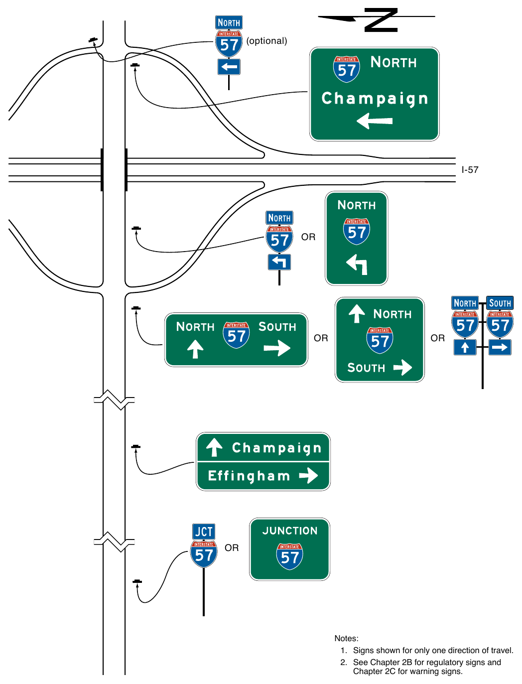
- 1. Signs shown for only one direction of travel.
- 2. See Chapter 2B for regulatory signs and Chapter 2C for warning signs.
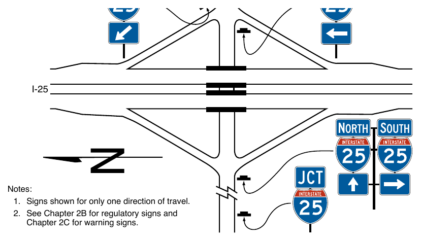
- 1. Signs shown for only one direction of travel.
- 2. See Chapter 2B for regulatory signs and Chapter 2C for warning signs.
Standard
12. If used, the post-mounted Advance Entrance Direction diagrammatic sign shall display only the two successive turns from the same side of the roadway, one of which shall be the entrance ramp. The post-mounted Advance Entrance Direction sign shall depict only the successive turns and shall not depict lane use with lane lines, multiple arrow shafts for the approach roadway, action messages, or other representations.
Support
13. Example guide signing for a transposed-alignment crossroad at a diamond interchange is shown in Figure 2D-21. Example guide signing for a single-point urban intersection at a diamond interchange is shown in Figure 2D-22.
14. Section 2D.50 contains information regarding the use of a Directional assembly or a FREEWAY ENTRANCE sign to mark the entrance to a freeway or expressway at the far corner of an intersection.
§2D.50 Freeway Entrance Signs (D13-3 and D13-3a)¶
Option
01. FREEWAY ENTRANCE (D13-3) signs or FREEWAY ENTRANCE with diagonal downward-pointing arrow (D13-3a) signs (see Figure 2D-18) may be used on entrance ramps near the crossroad to inform road users of the freeway or expressway entrance, as appropriate.
02. The D13-3 and D13-3a signs may display an alternate legend in place of FREEWAY, such as EXPRESSWAY or PARKWAY, as appropriate, or may display the name of an unnumbered highway.
03. A Directional assembly (see Section 2D.32) with a diagonal downward-pointing arrow (M6-2aP) auxiliary plaque (see Section 2D.28) may be used at the far left-hand corner of an intersection with a freeway or expressway entrance ramp as an alternative to the D13-3a sign, facing left-turning traffic on the conventional road approach to indicate the immediate point of entry to the freeway or expressway and distinguish the entrance ramp from an adjoining exit ramp terminal at the same intersection with the conventional road (see Figure 2D-18). A similar Directional assembly may be used at the far right-hand corner of an intersection with a freeway or expressway entrance ramp where the entrance ramp and a crossroad or side road follow one another in close succession on the conventional road approach and the point of entry to the freeway or expressway might be difficult for the road user to distinguish from the crossroad or side road on the conventional road approach (see Figure 2D-20).
Support
04. Section 2B.48 contains information regarding the use of regulatory signs to deter wrong-way movements at intersections of freeway or expressway ramps with conventional roads, and in the area where entrance ramps intersect with the mainline lanes.
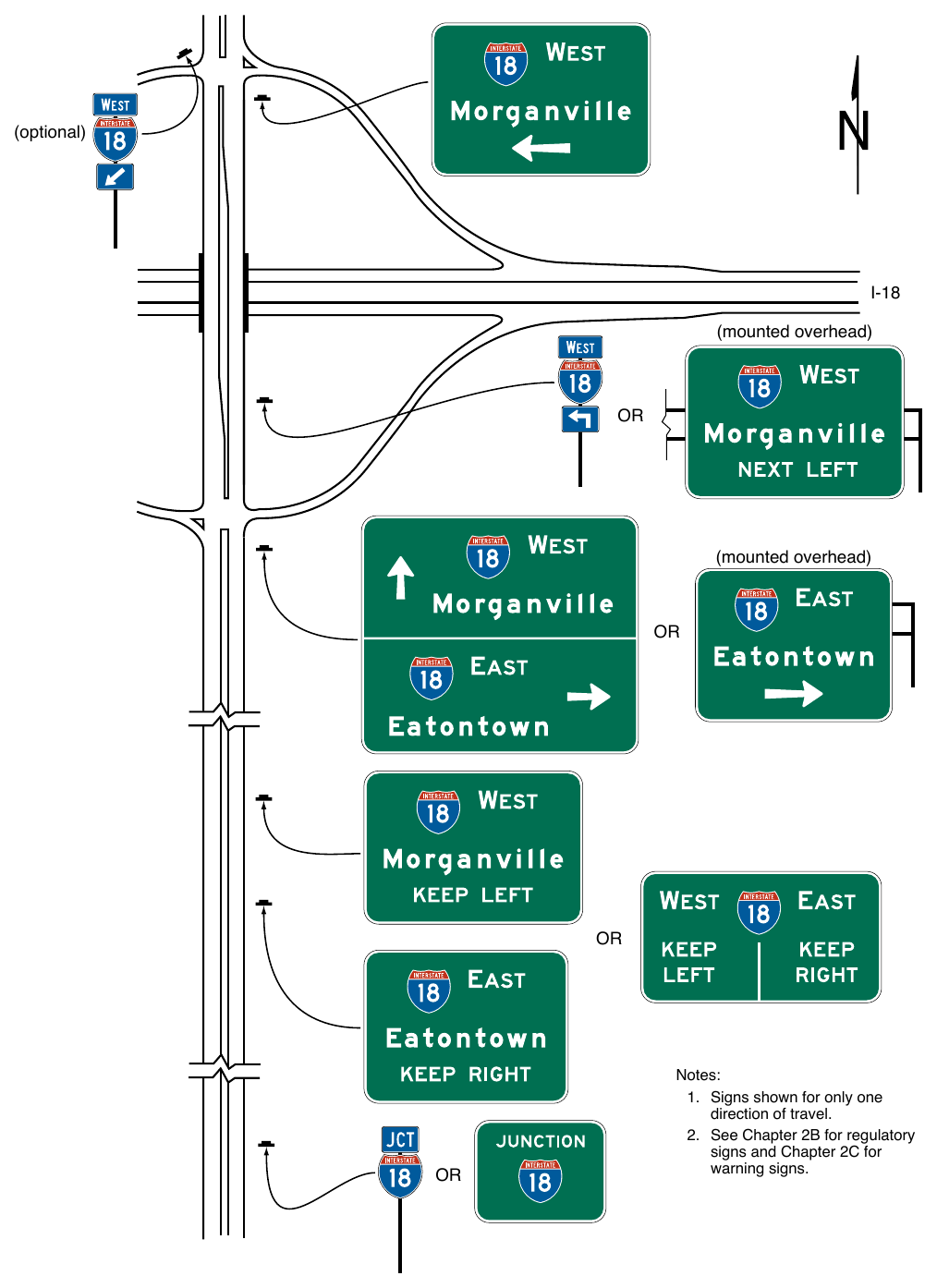
(mounted overhead) Notes:
- 1. Signs shown for only one direction of travel.
- 2. See Chapter 2B for regulatory signs and Chapter 2C for warning signs.
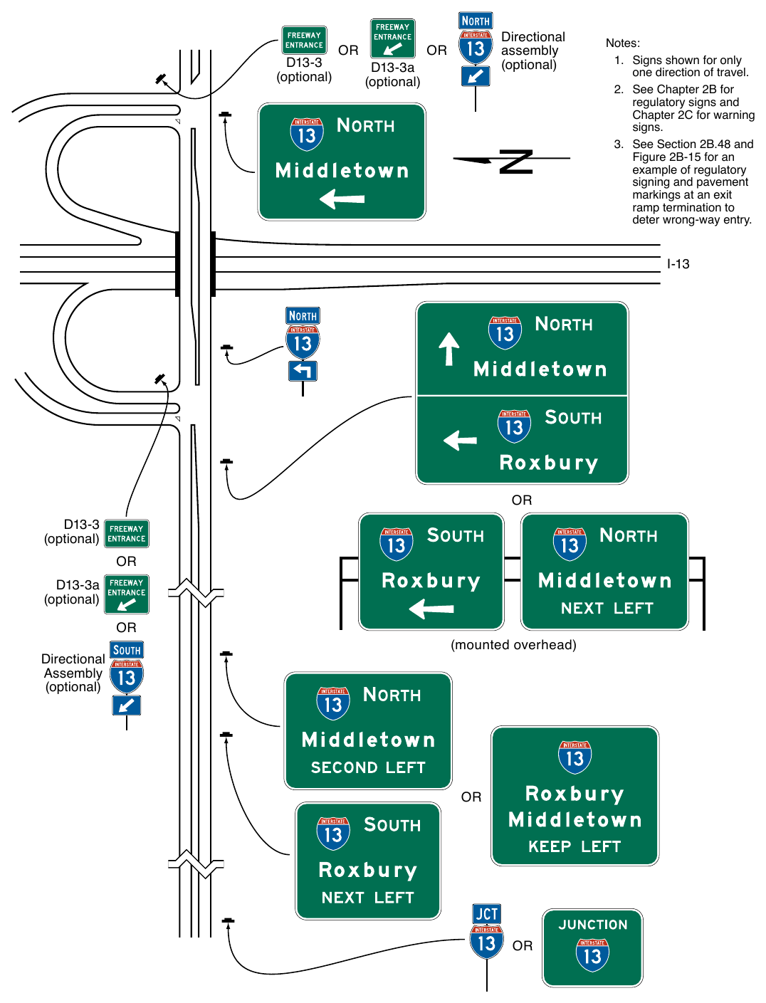
- 1. Signs shown for only one direction of travel.
- 2. See Chapter 2B for regulatory signs and Chapter 2C for warning signs.
- 3. See Section 2B.48 and Figure 2B-15 for an example of regulatory signing and pavement markings at an exit ramp termination to deter wrong-way entry. I-13 OR D13-3 (optional) OR D13-3a (optional) OR Directional Assembly (optional) (mounted overhead) OR OR
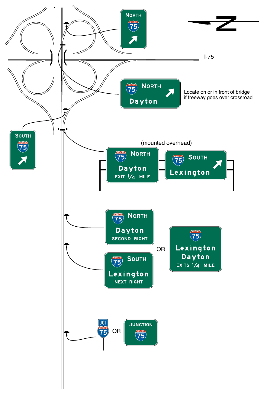
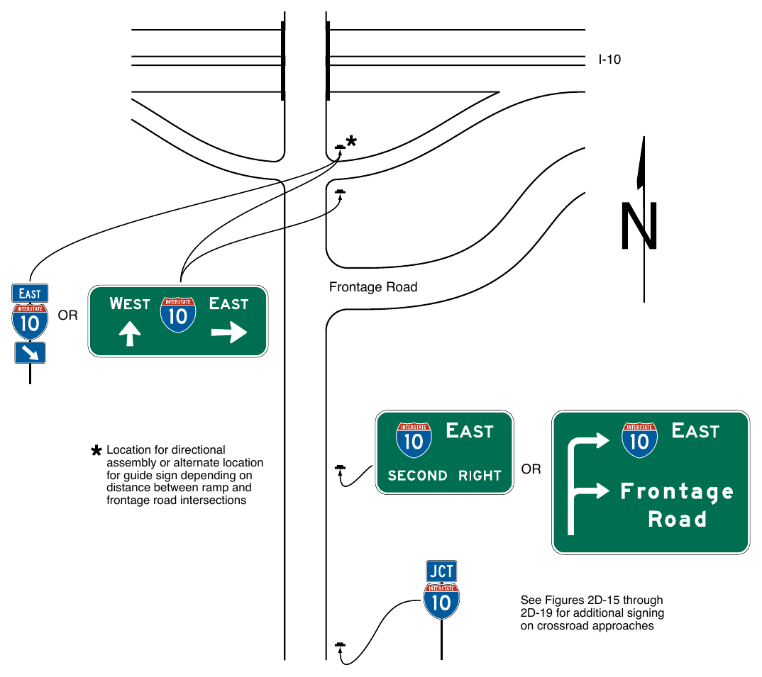
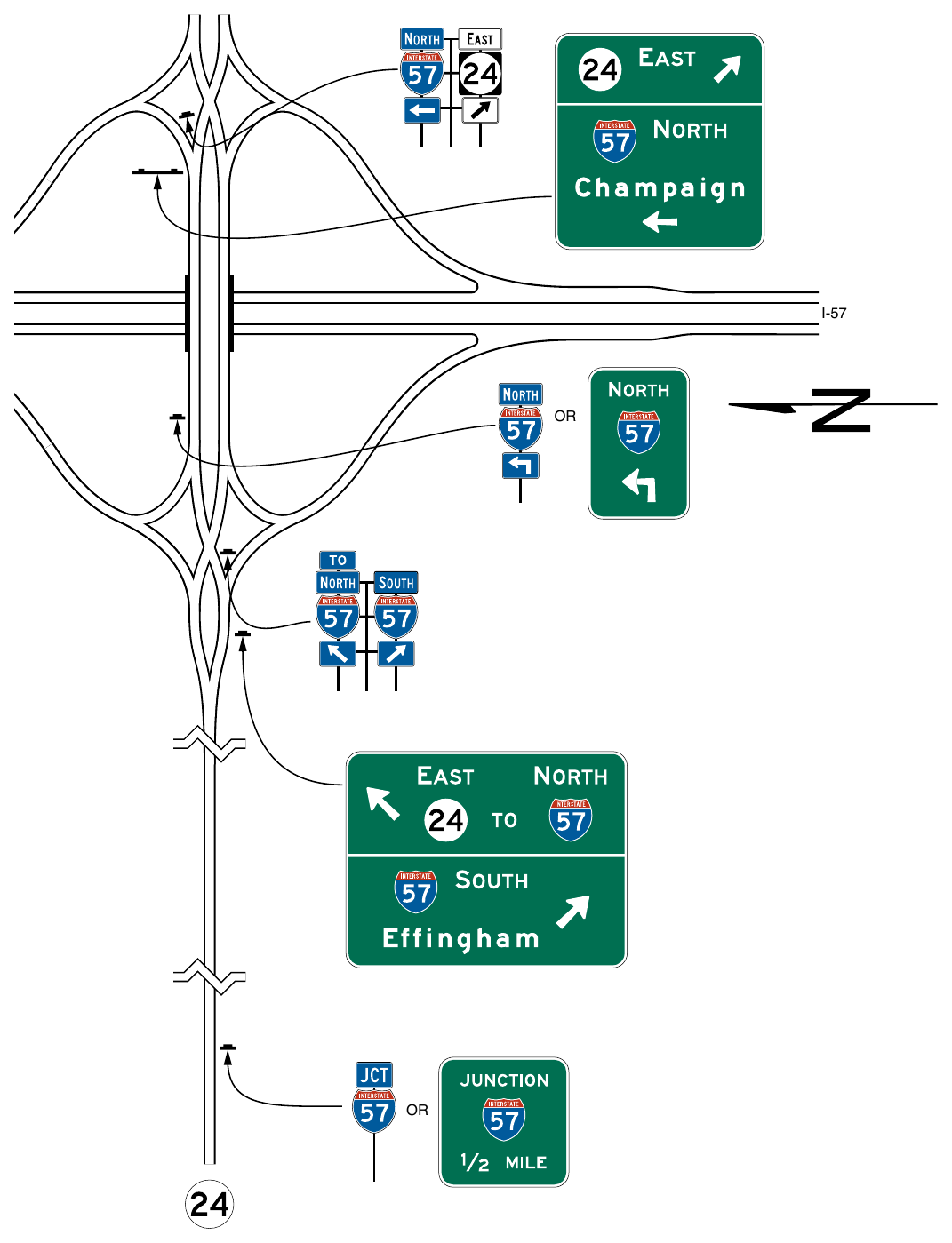
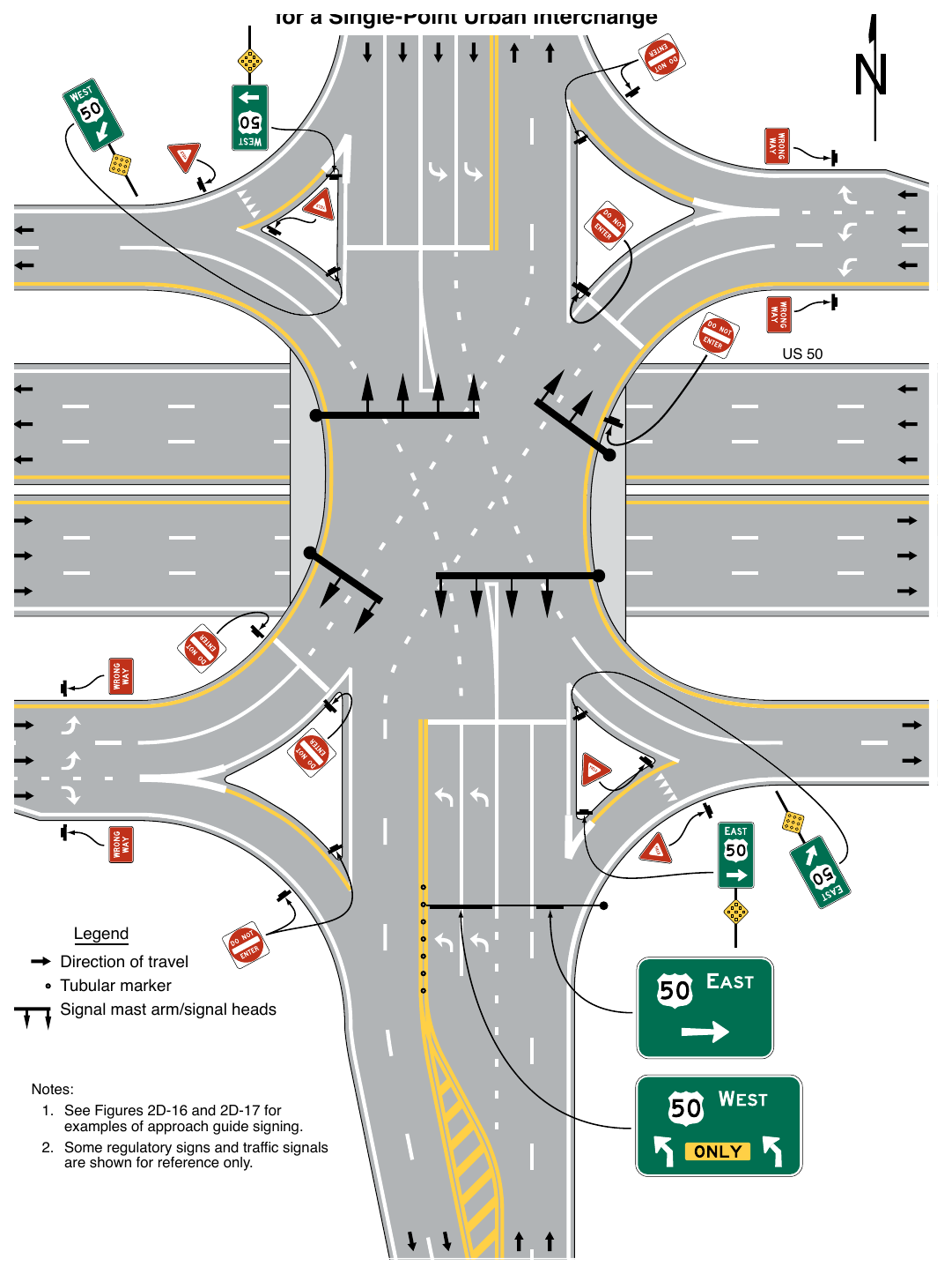
- 1. See Figures 2D-16 and 2D-17 for examples of approach guide signing.
- 2. Some regulatory signs and traffic signals are shown for reference only.
WEIGH STATION, CROSSOVER, TRUCK AND PASSING LANE, AND EMERGENCY AND SLOW VEHICLE TURN-OUT SIGNS¶
§2D.51 WEIGH STATION Signing (D8 Series)¶
Support
01. Independent facilities or areas have been added along many highways where certain commercial vehicles are directed to stop to be weighed and/or inspected. These areas are sometimes permanent, such as in a roadside area, or temporary mobile facilities deployed along the roadway.
02. The general concept for signing permanent Weigh Stations is similar to signing Rest Areas (see Section 2I.05) because in both cases traffic using either area remains within the right-of-way.
Standard
03. The standard sequence of signs for a Weigh Station on a conventional highway shall include three basic signs (see Figure 2D-23):
- A. Weigh Station Ahead (D8-1a) or Advance Weigh Station Distance (D8-1) sign,
- B. Weigh Station Advance Direction (D8-2) or Advance Weigh Station Distance (D8-1) sign, and
- C. Weigh Station Entrance Direction (D8-3) sign.
Guidance
04. A Gore sign with the same basic legend as the Weigh Station Entrance Direction (D8-3) sign should also be used to emphasize the entrance to the weigh station.
Option
05. Where State law requires trucks of a certain weight to enter the Weigh Station, a Weigh Station (R13-1) regulatory sign (see Section 2B.65) may be located following the Weigh Station Ahead sign (see Figure 2D-23).
06. Where only commercial vehicle inspections are conducted in the inspection area, the WEIGH STATION legend of the D8 series signs may be replaced with the alternate legend, COMMERCIAL VEHICLE INSPECTION.
Guidance
07. The Weigh Station Advance Direction (D8-2) sign, the Weigh Station Ahead (D8-1a) sign, or the Advance Weigh Station Distance (D8-1) sign should display, either on the sign or on a supplemental plaque or sign panel, the changeable legend OPEN or CLOSED.
Standard
08. When the WEIGH STATION legend of the D8 series signs is replaced with the COMMERCIAL VEHICLE INSPECTION legend, as provided in Paragraph 6 of this Section, the WEIGH STATION legend of the R13-1 sign shall likewise be replaced with the alternate legend.
§2D.52 Crossover Signs (D13-1 and D13-2)¶
Option
01. Crossover signs may be installed on divided highways to identify median openings not otherwise identified by warning or other guide signs.
Standard
02. A Crossover (D13-1) sign (see Figure 2D-24) shall not be used to identify a median opening that is permitted to be used only by official or authorized vehicles.
Guidance
03. If used, the Crossover sign should be installed immediately beyond the median opening, either on the right-hand side of the roadway or in the median.
Option
04. The Advance Crossover (D13-2) sign (see Figure 2D-24) may be installed in advance of the Crossover sign to provide advance notice of the crossover.
Guidance
05. The distance displayed on the Advance Crossover sign should be 1 MILE, ½ MILE, or ¼ MILE, unless unusual conditions require some other distance. If used, the sign should be installed either on the right-hand side of the roadway or in the median at approximately the distance displayed on the sign.
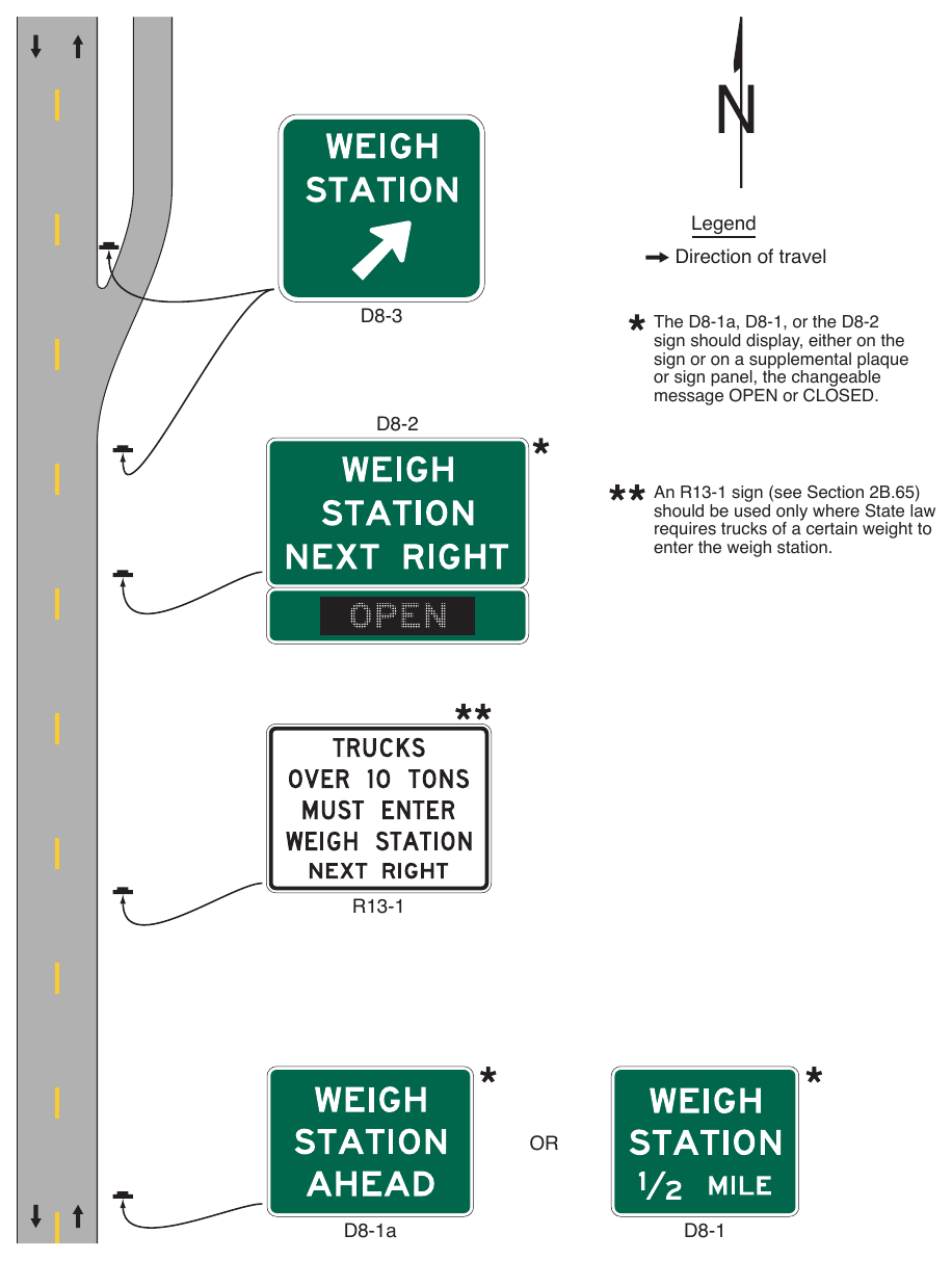
sign should display, either on the sign or on a supplemental plaque or sign panel, the changeable message OPEN or CLOSED. An R13-1 sign (see Section 2B.65) should be used only where State law requires trucks of a certain weight to enter the weigh station. D8-1a
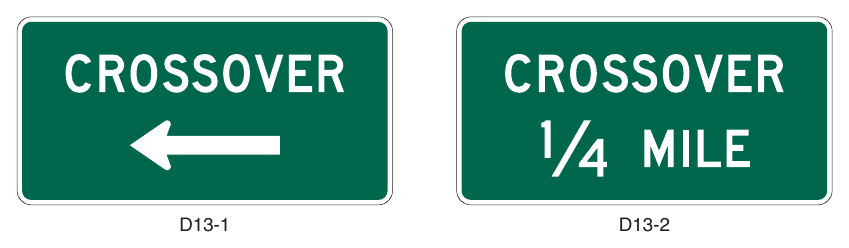
§2D.53 Truck and Passing Lane Signs (D17-1 through D17-4)¶
Guidance
01. If an extra lane has been provided to the right-hand side of the travel lane for use by trucks and other slow-moving traffic, an Advance Truck Lane (D17-2) sign (see Figure 2D-25) should be installed in advance of the lane.
02. If a series of truck lanes is provided along a highway, a Next Truck Lane (D17-1) sign (see Figure 2D-25) should be installed after each truck lane segment.
03. If an extra lane has been provided to the left-hand side of the travel lane for passing slower moving vehicles in the travel lane, an Advance Passing Lane (D17-4) sign (see Figure 2D-25) should be installed in advance of the lane.
04. If a series of passing lanes are provided along a highway, a Next Passing Lane (D17-3) sign (see Figure 2D-25) should be installed after each passing lane segment.
Support
05. An example of signing for a truck lane is shown in Figure 2D-26. An example of signing for an intermittent passing lane is shown in Figure 2D-27.
06. Section 2B.38 contains information regarding regulatory signs for these types of lanes.
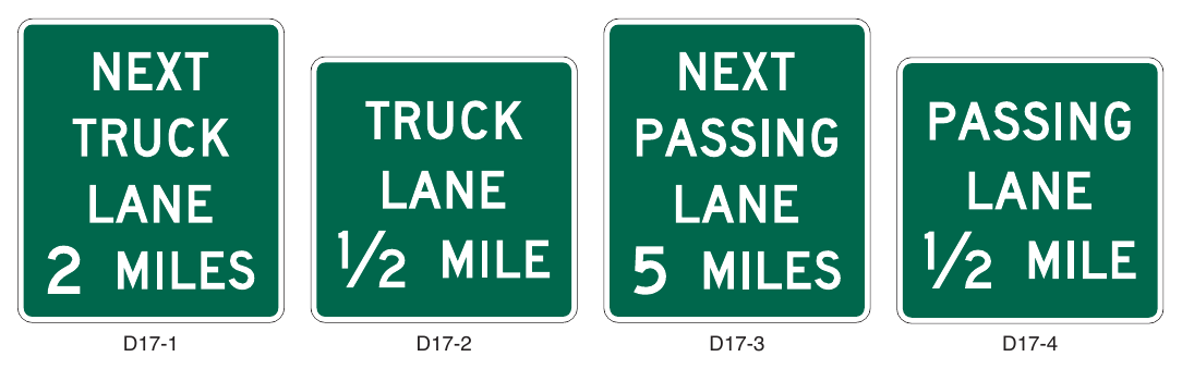
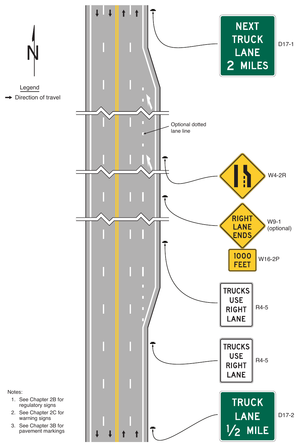
- 1. See Chapter 2B for regulatory signs
- 2. See Chapter 2C for warning signs
- 3. See Chapter 3B for pavement markings D17-2
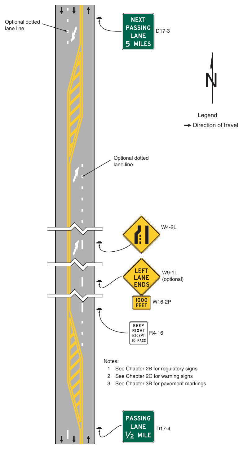
- 1. See Chapter 2B for regulatory signs
- 2. See Chapter 2C for warning signs
- 3. See Chapter 3B for pavement markings D17-4
§2D.54 Emergency and Slow Vehicle Turn-Out Signs (D17-5 through D17-7)¶
Guidance
01. If an emergency turn-out area has been provided where a shoulder is not available for emergency stopping or where there is part-time shoulder use by traffic (see Section 2G.23), Emergency Turn-Out signs should be installed. The Advance Emergency Turn-Out (D17-5) sign (see Figure 2D-28) should be installed between ¼ mile and 500 feet in advance of the turn-out area. The Emergency Turn-Out Directional (D17-6) sign (see Figure 2D-28) should be installed near the beginning of the turn-out area.
02. If a slow vehicle turn-out area has been provided for slow-moving traffic, an Advance Slow Vehicle Turn-Out (D17-7) sign (see Figure 2D-28) should be installed in advance of the turn-out area.
Support
03. An example of signing for an emergency turn-out is shown in Figure 2D-29.
04. Section 2B.42 contains information regarding regulatory signs for slow vehicle turn-out areas.
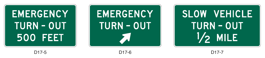
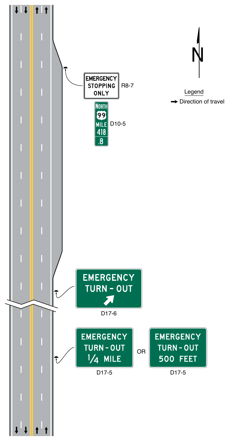
OTHER GUIDE SIGNS¶
§2D.55 Community Wayfinding Signs¶
Support
01. Community wayfinding guide signs are part of a coordinated and continuous system of signs that direct tourists and other road users to key civic, cultural, visitor, and recreational attractions and other similar secondary destinations within a city or a local urbanized or downtown area.
02. Community wayfinding guide signs are a type of destination guide sign for conventional roads with a common color and/or identification marker for destinations within an overall wayfinding guide sign plan for an area.
03. Figures 2D-30 through 2D-32 illustrate various examples of the design and application of community wayfinding guide signs.
Standard
04. The use of community wayfinding guide signs shall be limited to conventional roads. Community wayfinding guide signs shall not be installed on freeway or expressway mainlines or ramps. Direction to community wayfinding destinations from a freeway or expressway shall be limited to the use of a Supplemental guide sign (see Section 2E.51) on the mainline and a Destination sign (see Section 2D.36) on the ramp to direct road users to the area or areas within which community wayfinding guide signs are used. The individual wayfinding destinations shall not be displayed on the Supplemental guide and Destination signs except where the destinations are in accordance with the State or agency policy on Supplemental guide signs.
05. Community wayfinding guide signs shall not be used to provide direction to primary destinations or highway routes or streets. Destination or other guide signs shall be used for this purpose as described elsewhere in this Chapter and shall have priority over any community wayfinding sign in placement, prominence, and conspicuity.
06. Because regulatory, warning, and other guide signs have a higher priority, community wayfinding guide signs shall not be installed where adequate spacing cannot be provided between the community wayfinding guide sign and other higher-priority signs. Community wayfinding guide signs shall not be installed in a position where they would obscure the road users’ view of other traffic control devices.
07. Community wayfinding guide signs shall not be mounted overhead.
Guidance
08. If used, a community wayfinding guide sign system should be established on a local municipal or equivalent jurisdictional level or for an urbanized area of adjoining municipalities or equivalent that form an identifiable geographic entity that is conducive to a cohesive and continuous system of signs. Community wayfinding guide signs should not be used on a regional or statewide basis where infrequent or sparse placement does not contribute to a continuous or coordinated system of signing that is readily identifiable as such to the road user. In such cases, Destination or other guide signs detailed in this Chapter should be used to direct road users to an identifiable area in which the type of eligible destination described in Paragraph 1 of this Section is located.
09. When a system of community wayfinding guide signs is being considered, the system of existing guide signs should be evaluated for applicability and general compliance with the provisions of this Manual to ensure road user directional guidance is adequately being addressed.
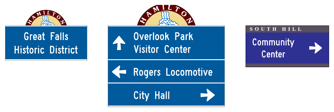
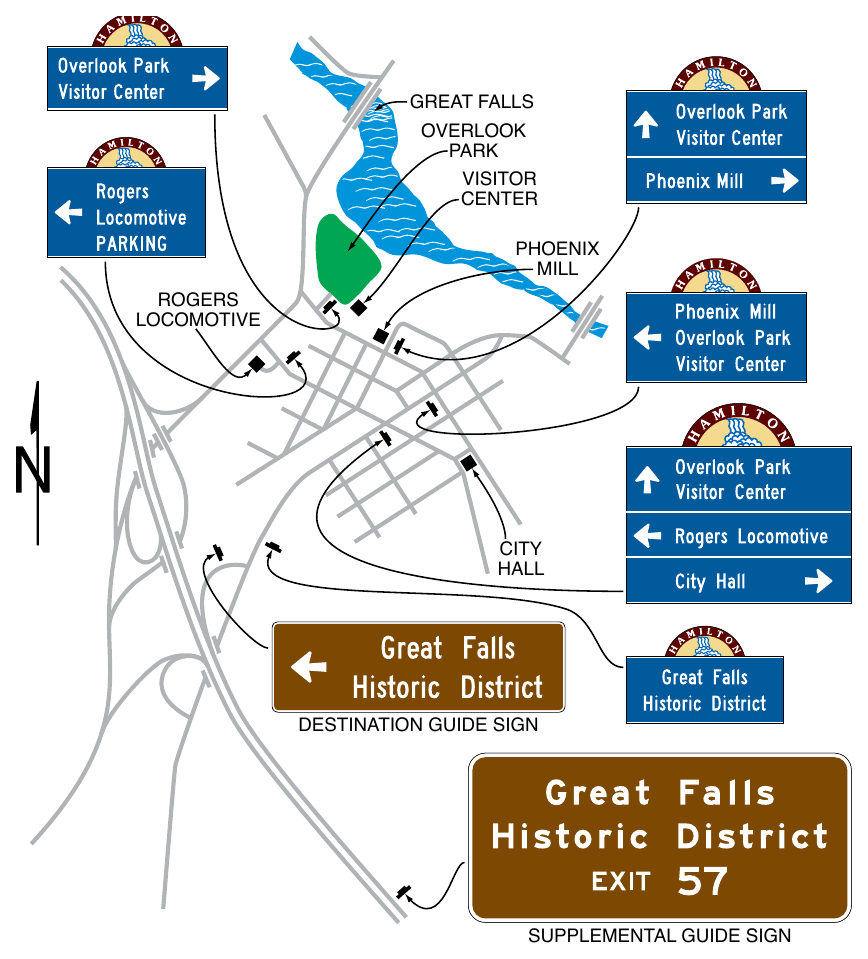
Support
10. The specific provisions of this Section regarding the design of community wayfinding sign legends apply to vehicular community wayfinding signs and do not apply to those signs that are intended only to provide information or direction to pedestrians or other users of a sidewalk or roadside area.
Guidance
11. Because pedestrian wayfinding signs typically use smaller legends that are inadequately sized for viewing by vehicular traffic and because they can provide direction to pedestrians that might conflict with that appropriate for vehicular traffic, wayfinding signs designed for and intended to provide direction to pedestrians or other users of a sidewalk or other roadside area should be located to minimize their conspicuity to vehicular traffic. Such signs should be located as far as practicable from the street, such as at the far edge of the sidewalk. Where locating such signs farther from the roadway is impracticable, the pedestrian wayfinding signs should have their conspicuity to vehicular traffic minimized by employing one or a combination of the following methods:
- A. Locating signs away from intersections where high-priority traffic control devices are present.
- B. Facing the pedestrian message toward the sidewalk and away from the street.
- C. Cantilevering the sign over the sidewalk if the pedestrian wayfinding sign is mounted at a height consistent with vehicular traffic signs, removing the pedestrian wayfinding signs from the line of sight in a sequence of vehicular signs.
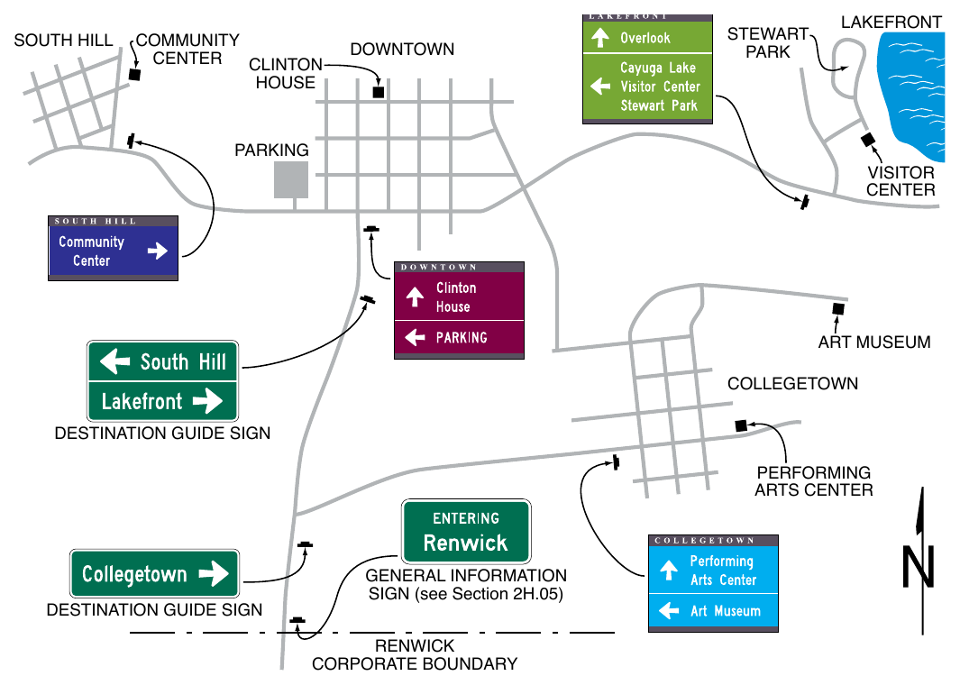
12. To further minimize their conspicuity to vehicular traffic during nighttime conditions, pedestrian wayfinding signs should not be retroreflective.
Support
13. Color coding is sometimes used on community wayfinding guide signs to help road users distinguish between multiple potentially confusing traffic generator destinations located in different neighborhoods or subareas within a community or area.
Option
14. At the boundaries of the geographical area within which community wayfinding guide signing is used, an informational guide sign may be posted to inform road users about the presence of wayfinding signing and to identify the meanings of the various color codes or pictographs that are being used.
Standard
15. These informational guide signs shall have a white legend and border on a green background and shall have a design similar to that illustrated in Figure 2D-1 and shall be consistent with the basic design principles for guide signs. These informational guide signs shall not be installed on freeway or expressway mainlines or ramps.
16. The color coding or a pictograph of the identification markers of the community wayfinding guide signing system shall be included on the informational guide sign posted at the boundary of the community wayfinding guide signing area. The color coding or pictographs shall apply to a specific, identifiable neighborhood or geographical subarea within the overall area covered by the community wayfinding guide signing. Color coding or pictographs shall not be used to distinguish between different types of destinations that are within the same designated neighborhood or subarea. The color coding shall be accomplished by the use of different colored square or rectangular panels on the face of the informational guide sign, each positioned to the left of the neighborhood or named geographic area to which the color-coding panel applies. The height of the colored square or rectangular panels shall not exceed 2 times the height of the upper-case letters of the principal legend on the sign.
Option
17. The different colored square or rectangular panels may include either a black or a white (whichever provides the better contrast with the color of the panel) letter, numeral, or other appropriate designation to identify the destination.
18. Except for the informational guide sign posted at the boundary of the wayfinding guide sign area, community wayfinding guide signs may use background colors other than green in order to provide a color identification for the wayfinding destinations by geographical area within the overall wayfinding guide signing system. Color-coded community wayfinding guide signs may be used with or without the boundary informational guide sign displaying corresponding color-coding panels described in Paragraphs 13 through 16 of this Section. Except as provided in Paragraph 19 of this Section, in addition to the colors that are approved in this Manual for use on official traffic control signs (see Section 2A.06), other background colors may also be used for the color coding of community wayfinding guide signs.
Standard
19. The standard colors of red, orange, yellow, purple, or the fluorescent versions thereof, fluorescent yellow-green, and fluorescent pink shall not be used as background colors for community wayfinding guide signs, in order to minimize possible confusion with critical, higher-priority regulatory and warning sign color meanings readily understood by road users.
20. The minimum contrast value of legend color to background color for community wayfinding guide signs shall be at least 0.70 (or 70%).
21. All messages, borders, legends, and backgrounds of community wayfinding guide signs and any identification markers shall be retroreflective (see Sections 2A.21 and 2A.22).
22. Community wayfinding guide signs, exclusive of any identification marker used, shall be rectangular in shape.
Guidance
23. Simplicity and uniformity in design, position, and application as described in Section 2A.04 are important and should be incorporated into the community wayfinding guide sign design and location plans for the area.
24. Community wayfinding guide signs should be limited to three destinations per sign (see Section 2D.06).
25. Abbreviations (see Section 1D.08) should be kept to a minimum, and should include only those that are commonly recognized and understood.
26. Horizontal lines of a color that contrasts with the sign background color should be used to separate groups of destinations by direction from each other.
Support
27. The basic requirement for all highway signs, including community wayfinding signs, is that they be legible to those for whom they are intended and that they be understandable in time to permit a proper response. Section 2A.04 contains additional information on the design of signs, including desirable attributes of effective designs.
Guidance
28. Word messages should be as brief as practical and the lettering should be large enough to provide the necessary legibility distance.
Standard
29. The minimum specific ratio of letter height to legibility distance shall comply with the provisions of Section 2A.08. The size of lettering used for destination and directional legends on community wayfinding signs shall comply with the provisions of minimum letter heights as provided in Section 2D.05.
30. Interline and edge spacing shall comply with the provisions of Section 2D.05.
31. Except as provided in Paragraph 34 of this Section, the lettering style used for destination and directional legends on community wayfinding guide signs shall comply with the provisions of Section 2D.04.
32. The lettering for destinations on community wayfinding guide signs shall be a combination of lower-case letters with initial upper-case letters (see Section 2D.04). All other word messages on community wayfinding guide signs shall be in all upper-case letters.
Guidance
33. Except as provided in Paragraphs 34 and 35 of this Section, letters, numerals, and other characters should be composed of the Standard Alphabets as detailed in the “Standard Highway Signs” publication (see Section 1A.05).
Option
34. A lettering style other than the Standard Alphabets provided in the “Standard Highway Signs” publication (see Section 1A.05) may be used on community wayfinding guide signs if an engineering study determines that the legibility and recognition values for the chosen lettering style meet or exceed the values for the Standard Alphabets for the same legend height and stroke width.
Standard
35. If a lettering style other than the Standard Alphabets is used, the alternative lettering style shall be conventional in form. The letters, numerals, and other characters shall not be italic, oblique, script, highly decorative, or of other unusual forms.
36. In accordance with Section 2A.04, except for signs that are designed and located with the intent to be viewed only by pedestrians, bicyclists stopped out of the flow of traffic, or occupants of parked vehicles, Internet and e-mail addresses, including domain names and uniform resource locators (URL), and scanning graphics for the purpose of obtaining information (see Section 2A.04), shall not be displayed on any community wayfinding guide sign or sign assembly.
37. The arrow location and priority order of destinations shall follow the provisions described in Sections 2D.08 and 2D.36. Arrows shall be of the designs provided in Section 2D.08.
Option
38. Pictographs (see definition in Section 1C.02) may be used on community wayfinding guide signs.
Standard
39. If a pictograph is used, its height shall not exceed 2 times the height of the upper-case letters of the principal legend on the sign.
40. Except for pictographs, symbols that are not approved in this Manual for use on guide signs shall not be used on community wayfinding guide signs.
41. Business logos, commercial graphics, or other forms of advertising (see Section 1D.07) shall not be used on community wayfinding guide signs or sign assemblies.
Option
42. Other graphics that specifically identify the wayfinding system, including identification markers, may be used on the overall sign assembly and sign supports.
Support
43. An identification marker consists of a shape, color, and/or pictograph that is used as a visual identifier for the community wayfinding guide signing system for an area. Figure 2D-30 shows examples of identification marker designs that can be used with community wayfinding guide signs.
Option
44. An identification marker may be used in a community wayfinding guide sign assembly, or may be incorporated into the overall design of a community wayfinding guide sign, as a means of visually identifying the sign as part of an overall system of community wayfinding signs and destinations.
Standard
45. The sizes and shapes of identification markers shall be smaller than the community wayfinding guide signs themselves. Identification markers shall not be designed to have an appearance that could be mistaken by road users as being a traffic control device.
Guidance
46. The area of the identification marker should not exceed ¹⁄5 of the area of the community wayfinding guide sign with which it is mounted in the same sign assembly.
§2D.56 Signing of Named Highways for Mapping and Address Purposes¶
Support
01. A highway name is the officially designated name of a freeway, expressway, or conventional road for navigational, official mapping, and address purposes. Some highways are named in addition to or in lieu of being assigned a highway route number. Memorial, honorary, ceremonial, or other secondary names, such as touring route and byway names, are not considered to be highway names.
Option
02. Guide signs may contain street or highway names if the purpose is to enhance driver communication and guidance; however, they are to be considered as supplemental information to route numbers.
Standard
03. Highway names shall not replace official numeral designations.
04. Memorial, honorary, or other secondary names (see Section 2M.10) shall not appear on supplemental signs or on any other information sign on or along the highway or its intersecting routes.
05. The use of route signs shall be restricted to signs officially used for guidance of traffic in accordance with this Manual and the “Purpose and Policy” statement of the American Association of State Highway and Transportation Officials that applies to Interstate and U.S. numbered routes.
Option
06. Unnumbered routes having major importance to proper guidance of traffic may be signed if carried out in accordance with the aforementioned policies. For unnumbered highways, a name to enhance route guidance may be used where the name is applied consistently throughout its length.
Guidance
07. Only one name should be used to identify any highway, whether numbered or unnumbered.
§2D.57 National Scenic Byways Sign and Plaque (M10-1 and M10-1aP)¶
Support
01. Certain roads have been designated by the U.S. Secretary of Transportation as National Scenic Byways or All-American Roads based on their archeological, cultural, historic, natural, recreational, or scenic qualities.
Option
02. State and local highway agencies may install the National Scenic Byways (M10-1) sign or (M10-1aP) plaque (see Figure 2D-33) at entrance points to a route that has been recognized by the U.S. Secretary of Transportation as a National Scenic Byway or an All-American Road. The M10-1 sign may be installed as independent Directional (see Section 2D.32) or Confirming (see Section 2D.33) assemblies at periodic intervals along the designated route and near intersections where the designated route turns or follows a different numbered highway. The M10-1aP plaque may be installed below a route sign in a Confirming assembly. At locations where roadside features have been developed to enhance the traveler’s experience such as rest areas, historic sites, interpretive facilities, or scenic overlooks, the National Scenic Byways sign or plaque may be placed on the associated sign assembly to inform travelers that the site contributes to the byway travel experience.
Guidance
03. Where the byway is identified only by the National Scenic Byways sign, the Directional assembly should consist of the M10-1 sign and an M5 series or M6 series auxiliary plaque when indication of a turn is necessary to remain on the byway route.
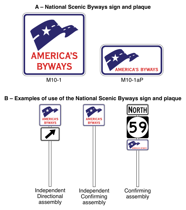
04. Where the name of the byway is to be displayed on identification signs or plaques along the byway route, the name should be displayed in a Directional or Confirming assembly as follows (see Figure 2D-34):
- A. On a Byway Identification (M10-2aP) plaque (see Section 2D.58) mounted below the M10-1 sign; or
- B. On a Byway Identification (M10-2) sign (see Section 2D.58) with the M10-1aP plaque mounted below the sign.
05. In either case, the size of the National Scenic Byways (M10-1) sign, (M10-1aP) plaque, Byway Identification (M10-2) sign, and Byway Identification (M10-2aP) plaque should be consistent with that specified for route signs (see Section 2D.10) for the roadway classification.
06. Where the name of the byway is to be displayed along the byway route as provided in Paragraph 4 of this Section, the byway Directional or Confirming assemblies should be located separately from any Route Sign assemblies or Destination guide signs.
Standard
07. When a National Scenic Byways sign is installed on a National Scenic Byway or an All-American Road, the design shown for the M10-1 sign or M10-1aP plaque in Figure 2D-33 shall be used. Use of this design shall be limited to routes that have been designated as a National Scenic Byway or All-American Road by the U.S. Secretary of Transportation.
08. If used, the M10-1 sign or M10-1aP plaque shall be placed such that the highway route signs have primary visibility for the road user.
09. The M10-1 sign or the M10-1aP plaque shall not be installed as sign panels on a guide sign or as part of a guide sign assembly.
§2D.58 State-Designated Scenic Byway, Historic Trail, and Auto Tour Route Signs¶
Support
01. Signing for State-designated scenic byways, historic trails, and auto tour routes, is similar in concept to that for National Scenic Byways as provided in Section 2D.57.
02. Named highways are officially designated and shown on official maps and serve the purpose of providing route guidance, primarily on unnumbered highways, and property addresses. A highway that is also designated as a trail, auto tour route, or byway is not considered to be a highway name for the purposes of highway signing or road user navigation and orientation. Section 2D.56 contains provisions for the signing of named highways.
03. Section 1D.09 provides information on the authority for placement of traffic control devices within the highway right-of-way.
Guidance
04. Route Sign assemblies and Destination guide signs should have priority in visibility and location over signing related to historic trails, auto tour routes, and byways.
Option
05. Identification signs for a State scenic byway may be installed along conventional roads that have been designated as part of a State scenic byway system. A Byway Identification (M10-2) sign (see Figure 2D-34) with the name of the byway displayed may be installed in a Directional or Confirming assembly with the SCENIC BYWAY (M10-3bP) plaque (see Figure 2D-34) mounted below the M10-2 sign.
06. Where a National Scenic Byway is part of a State scenic byway system, the National Scenic Byways (M10-1aP) plaque (see Section 2D.57) may be installed in a Directional or Confirming assembly below the Byway Identification (M10-2) sign or State Scenic Byway (M10-3 or M10-3a) sign (see Figure 2D-34) for the State scenic byway.
07. A State Scenic Byway System (M10-3) sign may be installed in a Directional or Confirming assembly with the name of the byway displayed on a Byway Identification (M10-2aP) plaque below the sign (see Figure 2D-34).
08. A State Scenic Byway (M10-3a) sign with a simple graphic and the name of the byway displayed may be installed in a Directional or Confirming assembly with the SCENIC BYWAY (M10-3bP) plaque mounted below the M10-3a sign.
09. Identification signs for a historic trail, such as the National Historic Trails administered by the National Park Service, may be installed along segments of conventional roads that coincide with the original route of the trail. National Historic Trail Identification (M11-1) signs (see Figure 2D-34) may be installed in a Directional or Confirming assembly with a HISTORIC ROUTE (M11-1aP), CROSSING (M11-1bP), or AUTO TOUR ROUTE (M11-1cP) auxiliary plaque (see Figure 2D-34) mounted below the M11-1 sign. The beginning and end of a historic trail route or auto tour route may be indicated with a BEGIN (M4-14P) or END (M4-6P) auxiliary plaque (see Figure 2D-5) with a white legend and border on a brown background mounted above the historic trail identification sign. The length of the route may be identified by a NEXT XX MILES (M11-1dP) auxiliary plaque mounted below the M11-1aP or M11-1cP auxiliary plaque.
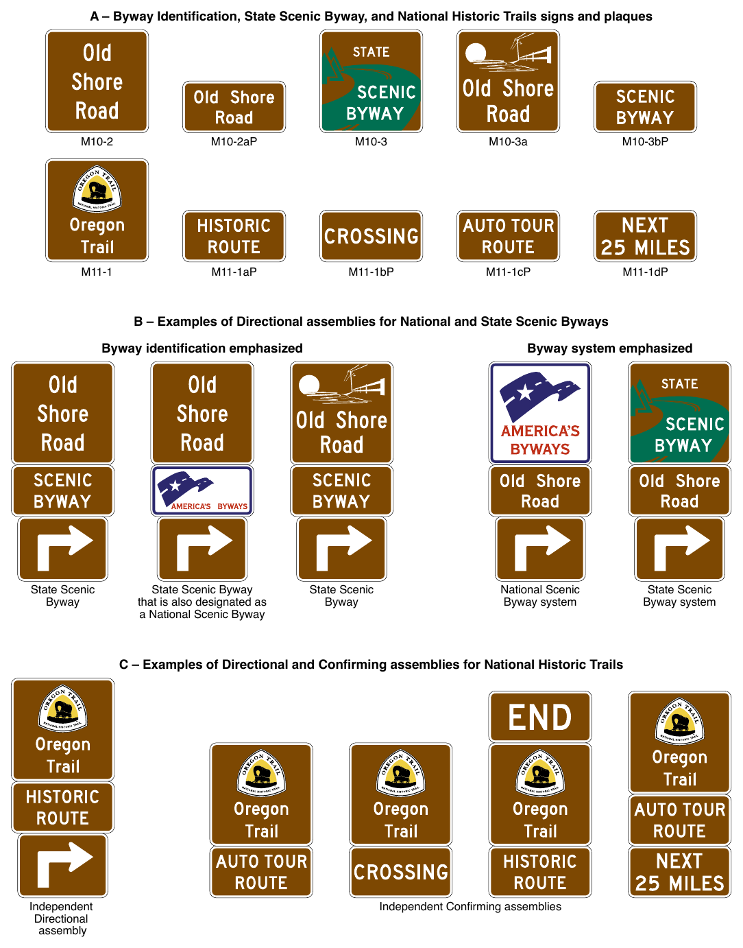
Signs shown: M10-2, M10-2aP, M10-3, M10-3a, M10-3bP, M11-1, M11-1aP, M11-1bP, M11-1cP, M11-1dP
Guidance
10. The design and size of historic trail and State scenic byway identification or system signs should comply with the general provisions and principles for route signs (see Section 2D.10). Designs should be simple, dignified, and devoid of complex graphics. The size of the signs should not exceed the size of the route signs used along a particular route.
Standard
11. Scenic byway, historic trail, and auto tour route sign designs shall not have a similar design to or resemble a highway route sign
Guidance
12. Where used, historic trail and State scenic byway identification signs should be installed as Directional (see Section 2D.32) or Confirming (see Section 2D.33) assemblies at independent locations, separate from other Route Sign assemblies and Destination guide signs. Where used, Confirming assemblies for the trail or byway should be installed at less frequent intervals than Confirming assemblies for the numbered route.
Support
13. Where all or part of the original route of a historic trail does not follow a roadway, an auto tour route is sometimes established along a conventional road in the general vicinity of the historical route of the trail. Examples include auto tour routes following other routes that parallel the original routes of the Lewis and Clark National Historic Trail, the Oregon National Historic Trail, and the Santa Fe National Historic Trail. The auto tour route is shown on touring maps along State or other highways and provides access to sites on the trail from those highways.
14. A system of signing providing direction along conventional roads for a historic trail with an auto tour route is shown in Figure 2D-35. Examples of Destination and Supplemental guide signs providing direction to historic trail sites from a freeway or expressway interchange are shown in Figure 2D-36.
Guidance
15. Signing for historic trails should be limited to Destination signs for the sites related to the trail and to Directional and Confirming assemblies for the original portions of the trail itself. If an auto tour route has been designated along other highways to provide access to sites along the original trail as described in Paragraph 13 of this Section, then the signing should be limited to Destination signs for those sites and directional signing to access the original route of the trail. Identification signs for the auto tour route should not be installed. Instead, direction along the auto tour route should rely on the touring map and other directional signs for the highways that the auto tour route follows.
Standard
16. Identification signs for historic trails, auto tour routes, and scenic byways shall not be installed on freeways or expressways, except as necessary to provide continuity between discontinuous segments of conventional roadways that are designated as a trail, auto tour route, or byway, for which the freeway or expressway provides the only connection between the segments. If installed on freeways or expressways, the identification signs shall be installed as independent trailblazer assemblies (see Sections 2D.34 and 2E.55) and shall not be installed with other route signs or Confirming assemblies or on guide signs. If installed on freeways or expressways, the trailblazer assemblies for the trail, auto tour route, or byway shall be installed at less frequent intervals than Confirming assemblies for the highway route.
17. Identification signs for historic trails, auto tour routes, and scenic byways shall not be installed as sign panels on a guide sign or as part of a guide sign assembly.
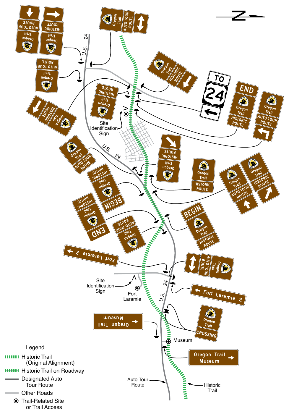
(Original Alignment) Historic Trail on Roadway Designated Auto Tour Route Other Roads Trail-Related Site or Trail Access Auto Tour Route Historic Trail
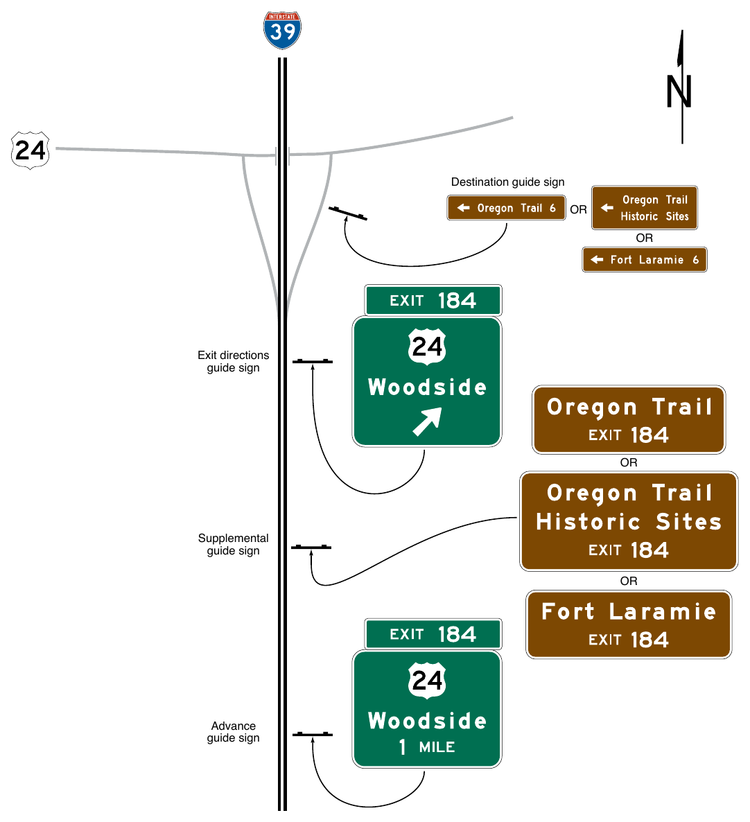
§2D.59 Emergency Routing Signs and Plaques (M4-11 and M4-12 Series)¶
Support
01. As part of an agency’s transportation incident management plan it is sometimes desirable to permanently sign routes that provide rerouting of traffic around highway segments susceptible to traffic incidents. Permanently-installed Emergency Routing signs and plaques (see Figure 2D-37) provide direction on conventional roads from an exit located upstream of an area that can be susceptible to traffic incidents back to the original route at a point downstream of the incident-susceptible area.
Option
02. EMERGENCY ROUTE (M4-11 and M4-11a) signs and EMERGENCY ROUTE TO (M4-11bP and M4-11cP) plaques mounted on a directional assembly may be permanently installed on conventional roadways to provide trailblazing along a designated diversionary route to bypass a traffic incident.
Support
03. The purpose of Emergency Routing signs and plaques is for corridor management along routes that have recurring incidents and have reasonable rerouting paths available. These signs are intended to be permanently installed to provide instant rerouting guidance to road users when traffic congestion or backups first begin even before emergency responders could provide temporary traffic control for rerouting traffic. These signs can be used as a stand-alone system or be a part of a larger system which might also incorporate other devices such as changeable message signs. These signs provide road users assurance that a diversionary route will lead them back to their original route of travel.
Standard
04. Emergency Routing signs and plaques shall only be installed at departure points and along diversion routes for directing road users around highway segments in areas that are more susceptible to traffic incidents (see Figure 2D-38). EMERGENCY ROUTE and EMERGENCY ROUTE TO signs shall be placed at each turning decision point along the designated route until it rejoins the original route or until other directional signs leading back to the original route are provided.
05. Emergency Routing signs shall have a white legend and border on a green background.
Option
06. For additional emphasis the legend EMERGENCY ROUTE or EMERGENCY ROUTE TO may be displayed in a yellow panel with black letters near the top of the sign (see Figure 2D-37).
Standard
07. Orange or pink shall not be used as alternate colors on permanently-installed signs or plaques for rerouting traffic during an incident or other event. If a route shield is displayed as part of the message, the wording of the sign or plaque shall be EMERGENCY ROUTE TO as shown in Figure 2D-37.
Option
08. An EMERGENCY ROUTE TO plaque with either a white legend and border on a green background (M4-11bP) or black legend and border on a yellow background (M4-11cP) may be added to the top of a conventional Route assembly on a diversion route to provide direction back to the original route downstream of the incident (see Figures 2D-37 and 2D-38).
09. A combination warning and regulatory message sign with flashing beacons mounted above and the legend, WHEN FLASHING [ROUTE] CLOSED AHEAD/ USE EMERGENCY ROUTE [NEXT RIGHT or EXIT XX] may be used in advance of the emergency route entrance to inform road users of the closure and require exiting the primary route and use of the emergency route (see Figures 2D-37 and 2D-38).
10. The End Emergency Route (M4-12) sign may be used at a point along the emergency route just prior to the junction where traffic is to reenter the primary route past the closed section of roadway (see Figures 2D-37 and 2D-38).
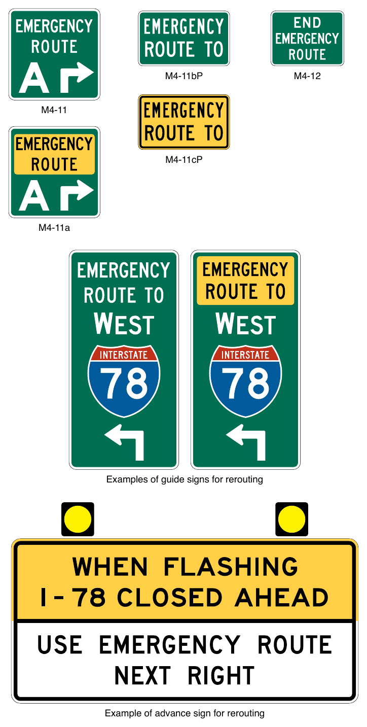
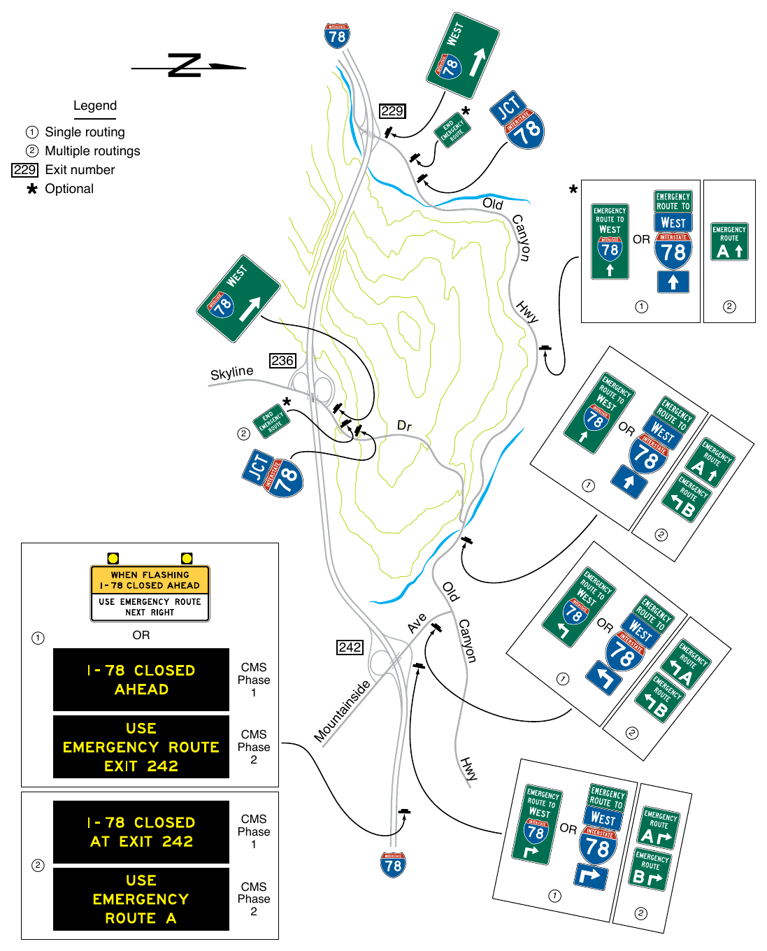
SIGNING AT AIRPORTS¶
§2D.60 Signing at Airports¶
Support
01. Many roadways within airport facilities (including terminal curbside roadways) are considered to be conventional roads because they typically have frequent driveways and at-grade intersections and might have pedestrian activity along and/or across them.
02. Some airport roadways have full or partial control of access and operating speeds higher than 45 mph and thus would be classified as freeways or expressways for signing purposes (see Chapter 2E). Freeway or expressway conditions typically exist on the approaches to the airport from other highways; on the approaches to access points to terminals, parking, and other patron facilities; and on roadways that provide exits from the airport facility to connect with the local or regional highway network.
03. Roadways within airports and other similarly-contained roadway networks with multiple closely-spaced access points to multiple destinations (such as terminals, parking facilities, rental car facilities, and other airport services) often present challenges for the application of guide signing. Closely-spaced signs, excessive sign messaging either co-located or in succession, and the resulting excessive informational load imposed on the road user are of particular concern for such roadways. The Transportation Research Board’s Airport Cooperative Research Program Report 52, “Wayfinding and Signing Guidelines for Airport Terminal and Landside,” contains additional information on the application of traffic control devices to the unique geometrics and roadway environment that are typical of airports.
04. An example of major guide signing on the approaches to and within an airport facility roadway network is shown in Figure 2D-39.
Guidance
05. If adequate sign spacing cannot be provided due to the site and roadway characteristics of an airport or similar facility, then measures should be taken to reduce the speeds of vehicles on the roadway to provide road users with adequate time to comprehend and respond to the sign messages. Consideration should also be given to increasing the sign letter heights to provide greater viewing distances and decision times. Where a single terminal serves a large number of airlines, the airline information should be displayed on separate signs that appear in sequence to limit the number of airlines displayed on a single sign or at a single location. Changeable message signs (see Chapter 2L) should not be used to rotate the display of airlines to an approaching road user.
Support
06. There are various methods that can be used to help reduce vehicle speeds, including roadway geometric changes, implementing traffic calming measures, and increased enforcement. Provisions on setting speed limits are found in Section 2B.21.
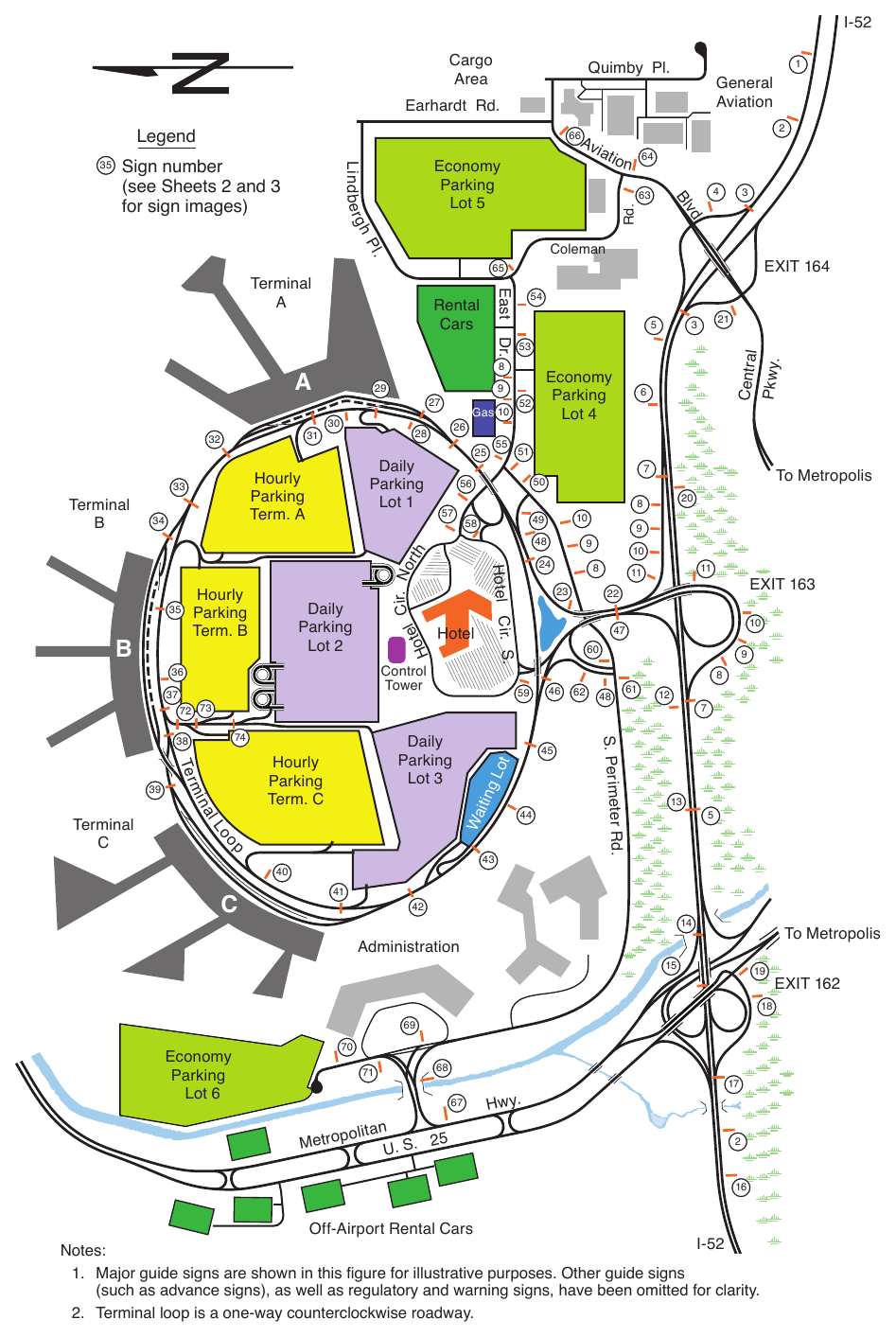
for an Airport Roadway Network (Sheet 1 of 3)
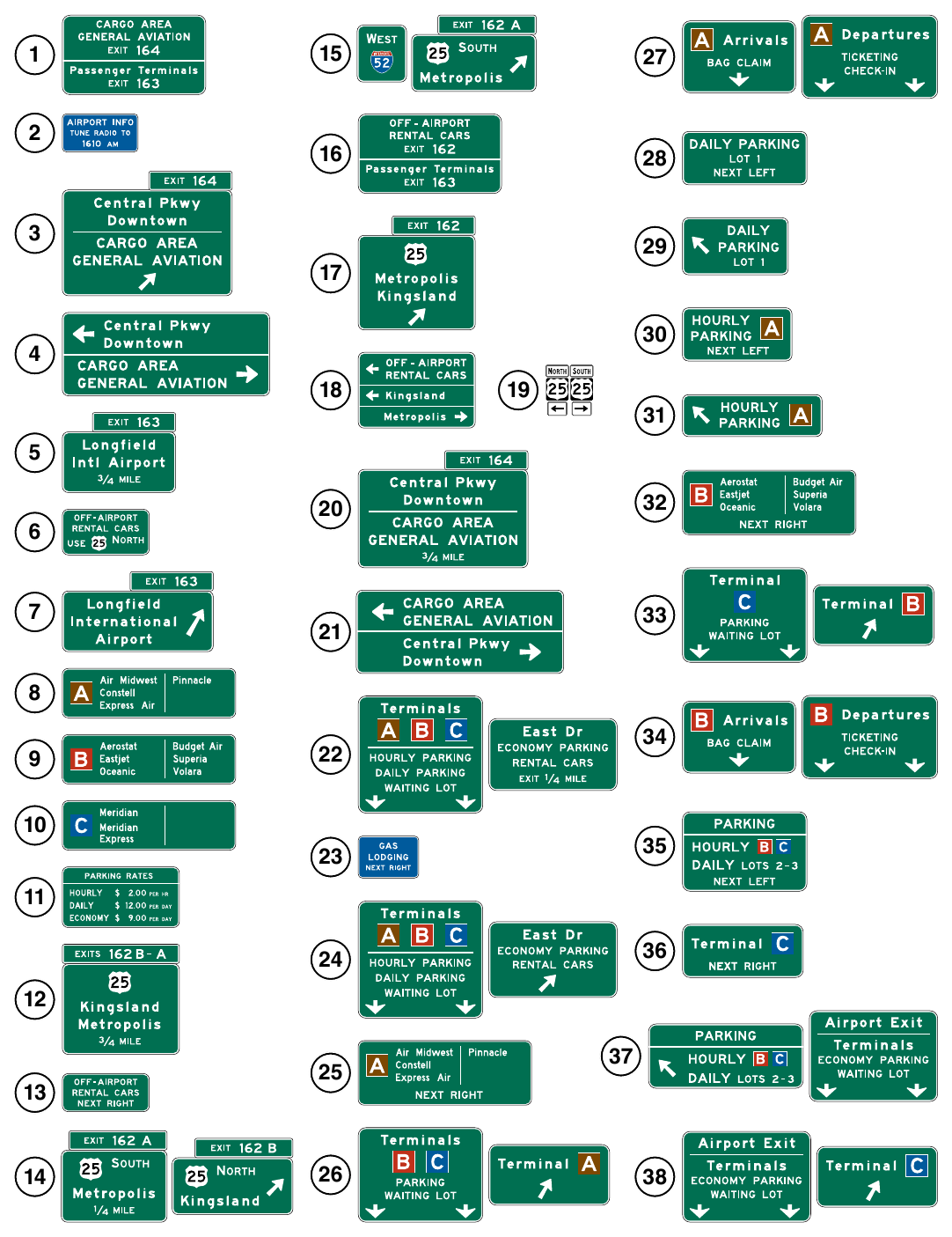
for an Airport Roadway Network (Sheet 2 of 3)
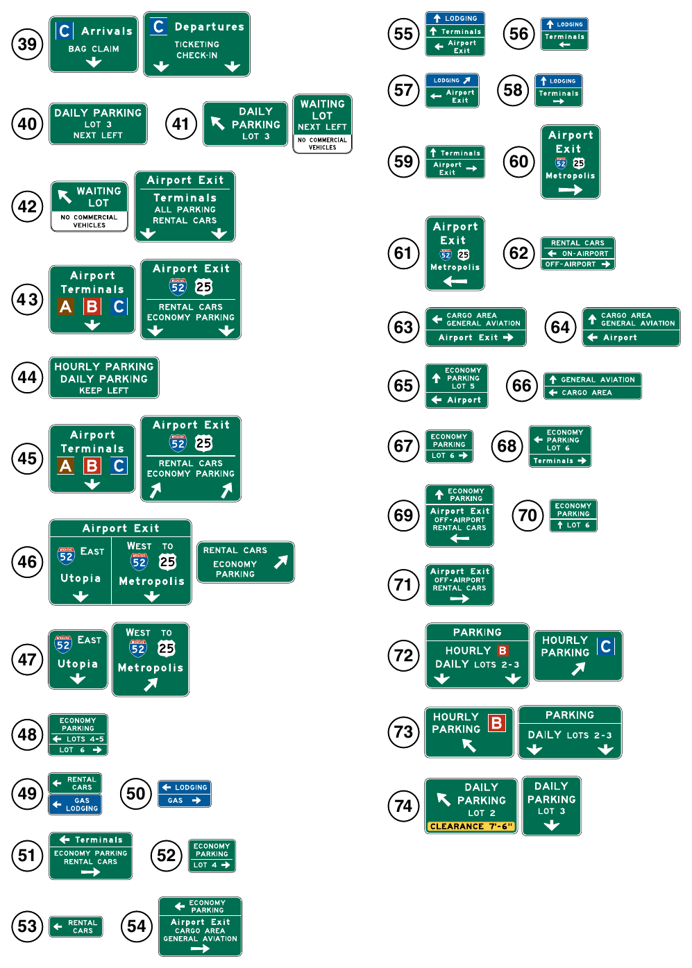
for an Airport Roadway Network (Sheet 3 of 3)