Chapter 3E. Preferential Lane Markings for Motor Vehicles¶
§3E.01 General¶
Support
01. Preferential lanes are established for one or more of a wide variety of special uses, including, but not limited to, high-occupancy vehicle (HOV) lanes, electronic toll collection (ETC) lanes, price-managed lanes, bus only lanes, taxi only lanes, and light rail transit only lanes.
02. This Chapter contains the pavement marking provisions for preferential lanes used by motor vehicles and light rail transit. Part 9 contains information for pavement markings for bicycle lanes.
03. Chapter 3H contains information for the use and application of colored pavement that can be used in preferential lanes to supplement the pavement markings described in this Chapter.
§3E.02 Longitudinal Markings¶
Support
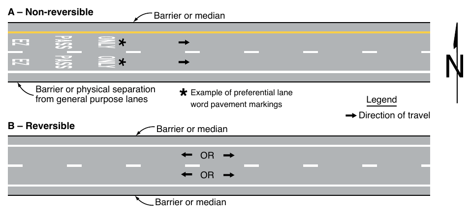
01. Preferential lanes can take many forms depending on the level of usage and the design of the facility. They might be barrier-separated or buffer-separated from the adjacent general-purpose lanes, or they might be contiguous with the adjacent general-purpose lanes. Barrier-separated preferential lanes might be operated in a constant direction or be operated as reversible lanes. Some reversible preferential lanes on a divided highway might be operated counter-flow to the direction of traffic on the immediately adjacent general-purpose lanes. Section 1C.02 contains definitions of these terms.
02. Preferential lanes might be operated full-time (24 hours per day on all days), for extended periods of the day, part-time (restricted usage during specific hours on specified days), or on a variable basis (such as a strategy for a managed lane).
Standard
03. The left-hand and right-hand edge lines and lane lines used for preferential lanes that are adjacent to general-purpose lanes where traffic is flowing in the same direction shall be in accordance with Table 3E-1.
04. If there are two or more preferential lanes for traffic moving in the same direction, the lane lines between the preferential lanes shall be normal width broken white lines.
05. Preferential lanes for motor vehicles shall have appropriate regulatory signs in accordance with Sections 2G.03 through 2G.07.
Support
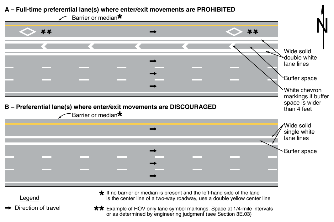
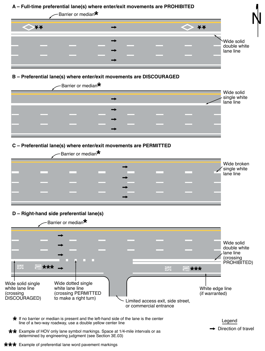
06. Figure 3E-1 illustrates pavement markings used for barrier-separated preferential lanes. Figure 3E-2 illustrates pavement markings used for buffer-separated preferential lanes. Figure 3E-3 illustrates pavement markings used for contiguous preferential lanes.
Guidance
07. Engineering judgment should determine the need for supplemental devices such as tubular markers, traffic cones, or other channelizing devices (see Chapter 3I).
08. Where preferential lanes and other travel lanes are separated by a buffer space wider than 4 feet and crossing the buffer space is prohibited, chevron markings (see Section 3B.25) should be placed in the buffer area (see Drawing A in Figure 3E-2).
09. The buffer space for a conventional road should be designed so that it is not misinterpreted as on-street parking, a bicycle lane, or any other type of lane.
Option
10. If a full-time or part-time contiguous preferential lane is separated from the other travel lanes by a wide broken single white line (see Drawing C in Figure 3E-3), the spacing or skip pattern of the line may be reduced and the width of the line may be increased.
Standard
11. At direct exits from a preferential lane, dotted white line markings shall be used to separate the tapered or parallel deceleration lane for the direct exit (including the taper) from the adjacent continuing preferential through lane, to reduce the chance of unintended exit maneuvers.
12. Signs (see Section 2B.34), lane-use control signals (see Chapter 4T), or both shall be used to supplement the reversible lane markings on a divided highway where a part-time counter-flow preferential lane is present.
Table 3E-1. Standard Edge Line and Lane Line Markings for Preferential Lanes
| Type of Preferential Lane | Left-Hand Line | Right-Hand Line |
|---|---|---|
| Barrier-Separated, Non-Reversible | A normal solid single yellow edge line | A normal solid single white edge line (see Drawing A in Figure 3E-1) |
| Barrier-Separated, Reversible | A normal solid single white edge line | A normal solid single white edge line (see Drawing B in Figure 3E-1) |
| Buffer-Separated, Left-Hand Side | A normal solid single yellow edge line | A wide solid double white line along both edges of the buffer space where crossing is prohibited (see Drawing A in Figure 3E-2) A wide solid single white line along both edges of the buffer space where crossing is discouraged (see Drawing B in Figure 3E-2) A wide broken single white line along both edges of the buffer space, or a wide broken single white line within the buffer space (resulting in wider lanes), where crossing is permitted (see Drawing C in Figure 3E-2) |
| Buffer-Separated, Right-Hand Side | A wide solid double white line along both edges of the buffer space where crossing is prohibited, or a wide solid single white line along both edges of the buffer space where crossing is discouraged (see Drawing D in Figure 3E-2) A wide broken single white line along both edges of the buffer space, or a wide broken single white line within the buffer space (resulting in wider lanes), where crossing is permitted (see Drawing D in Figure 3E-2) A wide dotted single white line within the buffer space (resulting in wider lanes) where crossing is permitted for any vehicle to perform a right-turn maneuver (see Drawing D in Figure 3E-2) | A normal solid single white edge line (if warranted) |
| Contiguous, Left-Hand Side | A normal solid single yellow edge line | A wide solid double white lane line where crossing is prohibited (see Drawing A in Figure 3E-3) A wide solid single white lane line where crossing is discouraged (see Drawing B in Figure 3E-3) A wide broken single white lane line where crossing is permitted (see Drawing C in Figure 3E-3) |
| Contiguous, Right-Hand Side | A wide solid double white lane line where crossing is prohibited (see Drawing D in Figure 3E-3) A wide solid single white lane line where crossing is discouraged (see Drawing D in Figure 3E-3) A wide broken single white lane line where crossing is permitted (see Drawing D in Figure 3E-3) A wide dotted single white lane line where crossing is permitted for any vehicle to perform a right-turn maneuver (see Drawing D in Figure 3E-3) | A normal solid single white lane line (if warranted) |
Notes: 1. If there are two or more preferential lanes, the lane lines between the preferential lanes shall be normal broken white lines. 2. The standard lane markings listed in this table are provided in a tabular format for reference.
Notes: 1. If there are two or more preferential lanes, the lane lines between the preferential lanes shall be normal broken white lines.
- 2. The standard lane markings listed in this table are provided in a tabular format for reference.
A – Full-time preferential lane(s) where enter/exit movements are PROHIBITED Barrier or median lane lines B – Preferential lane(s) where enter/exit movements are DISCOURAGED Barrier or median White chevron markings if buffer than 4 feet lane lines Legend Direction of travel If no barrier or median is present and the left-hand side of the lane is the center line of a two-way roadway, use a double yellow center line Example of HOV only lane symbol markings. Space at 1/4-mile intervals or as determined by engineering judgment (see Section 3E.03) The longitudinal pavement markings used for preferential lanes that are adjacent to general-purpose lanes where traffic is flowing in the opposite direction (see Figure 3E-4) shall be in accordance with Table 3E-2.
Support
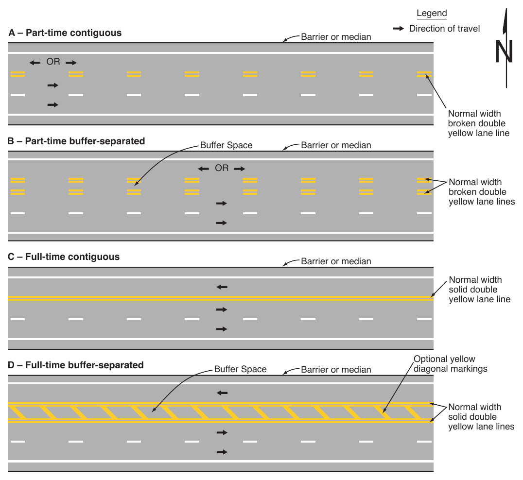
14. Figure 3E-4 illustrates pavement markings used for counter-flow preferential lanes on divided highways or on transitions to and from other divided highways such as bridges and crossovers.
Option
15. Cones, tubular markers, or other channelizing devices (see Chapter 3I) may also be used in addition to longitudinal markings to separate the opposing lanes when a counter-flow preferential lane operation is in effect.
§3E.03 Preferential Lane Word and Symbol Markings¶
Support
01. Sections 3B.20 through 3B.22 contain information on general applications of word and symbol markings.
Standard
02. When a preferential lane is established, the preferential lane shall be marked with one or more of the following word or symbol markings for the preferential lane use specified:
- A. HOV lane—white lines formed in a diamond-shaped symbol or the word message HOV. The diamond shall be at least 2.5 feet wide and 12 feet in length. The lines shall be at least 6 inches in width.
- B. ETC Account-Only lane—except as provided in Paragraph 8 of this Section, a word marking or pictograph using the name of the ETC payment system required for use of the lane, such as E-Z PASS ONLY.
- C. Price-managed lane—the word marking EXPRESS or EXPRESS LANE(S) (see Section 2G.17).
- D. Bus only lane or bus stop—the word marking BUS ONLY or BUS STOP.
- E. Taxi only lane or taxi stand —the word marking TAXI ONLY or TAXI STAND.
- F. Light rail transit lane—the word marking LRT ONLY.
- G. Other type of preferential lane—a word marking appropriate to the restriction.
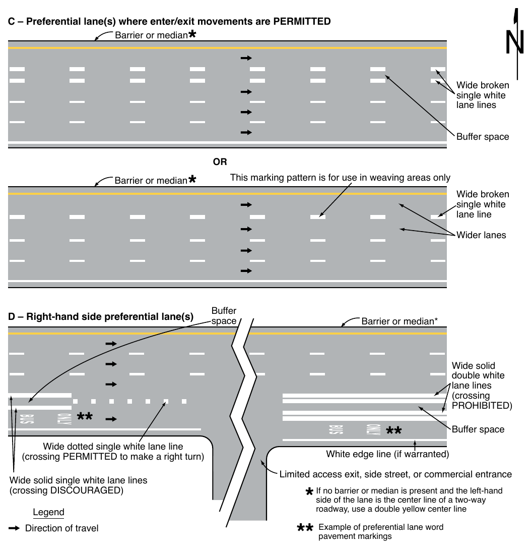
Table 3E-2. Standard Center Line and Edge Line Markings for Counter-Flow Preferential Lanes on Divided Highways
| Type of Preferential Lane | Center Line on Left-Hand Side | Edge Line on Left-Hand Side |
|---|---|---|
| Part-Time Contiguous | A normal width broken double yellow line | A normal solid single white line (if warranted) |
| Part-Time Buffer-Separated | A normal width broken double yellow line along both edges of the buffer space | A normal solid single white line (if warranted) |
| Full-Time Contiguous | A normal width solid double yellow line | A normal solid single white line (if warranted) |
| Full-Time Buffer-Separated | A normal width solid double yellow line along both edges of the buffer space | A normal solid single white line (if warranted) |
Guidance
03. If multiple preferential lane uses are allowed in a single lane, the word or symbol marking for each preferential lane should be used.
Standard
04. Pavement word or symbol markings for motorcycles and Inherently Low Emission Vehicles (ILEV) shall not be used to mark the preferential lane if motorcycles and ILEVs are allowed to use
Support
05. Motorcycles and Inherently Low Emission Vehicles (ILEV) that are allowed to use a preferential lane are granted an exception such as through an established High-Occupancy Vehicle (HOV) regulation. Communicating that motorcycles and ILEVs are allowed to use the preferential lane is accomplished through regulatory signing (see Sections 2G.03 and 2G.04) that complements HOV signing.
Standard
06. Static or changeable message regulatory signs (see Sections 2G.03 through 2G.07) shall be used with preferential lane word or symbol markings.
07. All preferential lane word and symbol markings shall be white and shall be positioned laterally in the approximate center of the preferential lane.
Option
08. Preferential lane-use symbol or word markings may be omitted at toll plazas where physical conditions preclude the use of the markings.
09. Lane-use arrow markings may be placed on the curb lanes on approaches to intersections to signify nonpreferential road users can use the lane for turning movements.
Guidance
10. All longitudinal pavement markings, as well as word and symbol pavement markings, associated with a preferential lane should end at approximately where the Preferential Lane Ends (R3-12a or R3-12c) sign (see Section 2G.07) designating the downstream end of the preferential only lane restriction is installed.
11. The spacing of the markings should be based on engineering judgment that considers the operating speed, block lengths, distance from intersections, and other factors that affect clear communication to the road user.
12. In addition to a regular spacing interval, the preferential lane marking should be placed at strategic locations such as major decision points, direct exit ramp departures from the preferential lane, and along access openings to and from adjacent general-purpose lanes. At decision points, the preferential lane marking should be placed on all applicable lanes and should be visible to approaching traffic for all available departures. At direct exits from preferential lanes where extra emphasis is needed, the use of word markings (such as “EXIT” or “EXIT ONLY”) in the deceleration lane for the direct exit and/or on the direct exit ramp itself just beyond the exit gore should be considered.
Option
13. A numeral indicating the vehicle occupancy requirements established for a high-occupancy vehicle lane may be included in sequence after the diamond symbol or HOV word message.
§3E.04 Markings for Part-Time Travel on a Shoulder¶
Support
01. Shoulders are sometimes used to add capacity to a roadway in peak hour conditions to provide for transit or HOV priority or to provide higher throughput when open to all traffic.
02. A shoulder that has been opened to travel on a permanent, rather than a part-time basis is considered to be a travel lane and is signed and marked in accordance with other provisions of this Manual.
Standard
03. When part-time travel on a shoulder is open to all traffic, pavement word and symbol markings shall not be used in the shoulder.
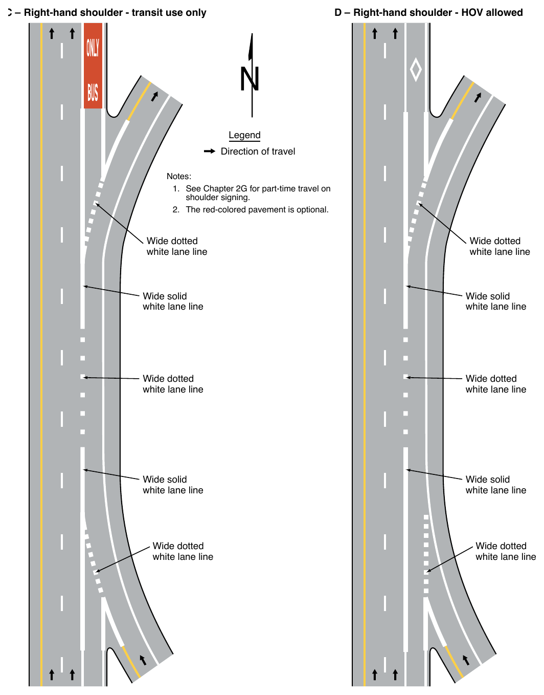
04. When a shoulder is assigned part-time to a particular class or classes of vehicles, the shoulder shall be marked with one or more pavement word markings that identify the special use of the shoulder such as BUS ONLY, TRANSIT ONLY, HOV, or instead of the HOV pavement word marking, white lines formed in a diamond-shaped symbol (see Section 3E.03). A pavement word or symbol marking shall be provided in the shoulder immediately after exit and entry ramps (see Figure 3E-5) or immediately departing an intersection at the full-width shoulder (see Figure 3E-6). Appropriate regulatory signing (see Section 2G.03) shall be installed with the pavement word or symbol markings.
05. The channelizing line emanating from the entrance ramp shall be a wide dotted line through the intersecting alignment of the shoulder to the theoretical gore (see Drawings A and B in Figure 3E-5). At exit ramps, the channelizing line proceeding from the theoretical gore across the intersecting alignment of the shoulder shall be a wide dotted line (see Figure 3E-5).
06. If used, the extension of the channelizing line at entrance ramps proceeding from the theoretical gore across the opening of the on-ramp alignment shall be a wide dotted line (see Drawing C in Figure 3E-5) where it is demonstrated that traffic entering from an on-ramp stops or yields to traffic on the shoulder of the highway mainline.
07. An additional outside solid edge line shall be provided on the shoulder in accordance with Sections 3B.09 and 3B.10.
Guidance
08. Changes in edge line pattern or direction should occur at appropriate regulatory signs.
Option
09. At locations where traffic is allowed to enter, exit, or merge with the shoulder, a dotted edge line may be used either in a continuous manner or angled to the pavement edge (see Figure 3E-6).
10. Red-colored pavement (see Section 3H.07) may be used on shoulders that allow only transit vehicles.
Standard
11. If used, red-colored pavement shall be discontinued on the shoulder through the influence area of the ramp (see Figure 3E-5).
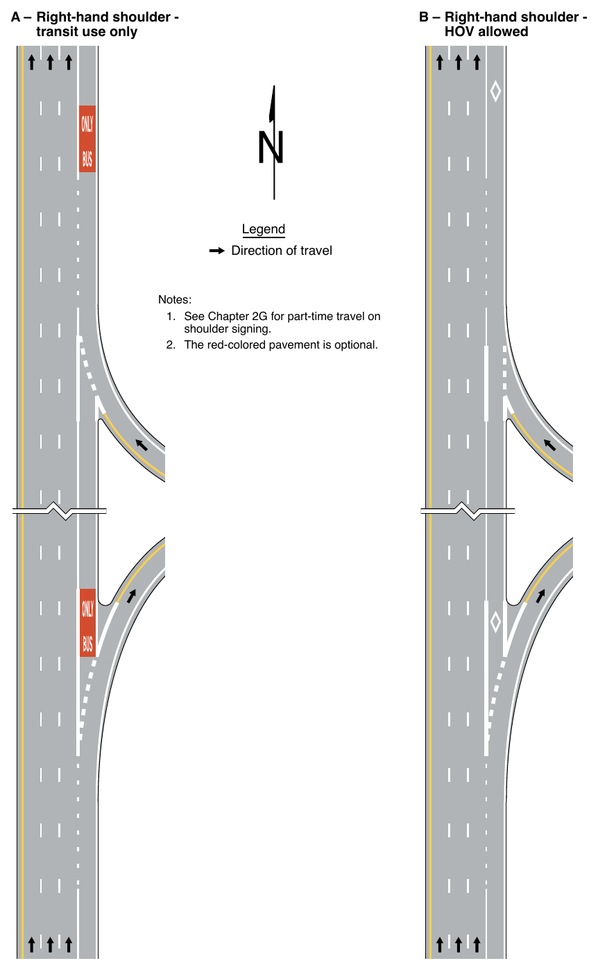
- 1. See Chapter 2G for part-time travel on shoulder signing.
- 2. The red-colored pavement is optional.
- 1. See Chapter 2G for part-time travel on shoulder signing.
- 2. The red-colored pavement is optional. Wide dotted white lane line Wide dotted white lane line Wide solid white lane line Wide solid white lane line Wide dotted white lane line Wide dotted white lane line Wide solid white lane line Wide solid white lane line Wide dotted white lane line Wide dotted white lane line
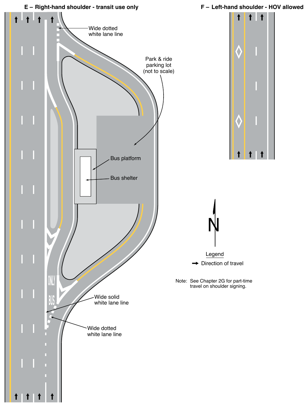
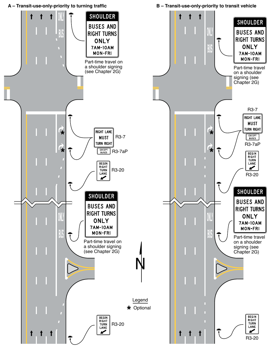
(see Chapter 2G) Part-time travel on a shoulder signing (see Chapter 2G) R3-7aP R3-7aP Part-time travel on a shoulder signing (see Chapter 2G) Part-time travel on a shoulder signing (see Chapter 2G) Legend Optional